Throttle BMW 525i 2001 E39 Workshop Manual
[x] Cancel search | Manufacturer: BMW, Model Year: 2001, Model line: 525i, Model: BMW 525i 2001 E39Pages: 1002
Page 46 of 1002
Downloaded from www.Manualslib.com manuals search engine
020-1 4
Maintenance
- When oil flow has diminished to an occasional drip, reinstall
drain plug with a new metal sealing washer and torque plug.
Tightening torque Engine oil drain plug to oil pan
25 Nrn (1.8 ft-lb)
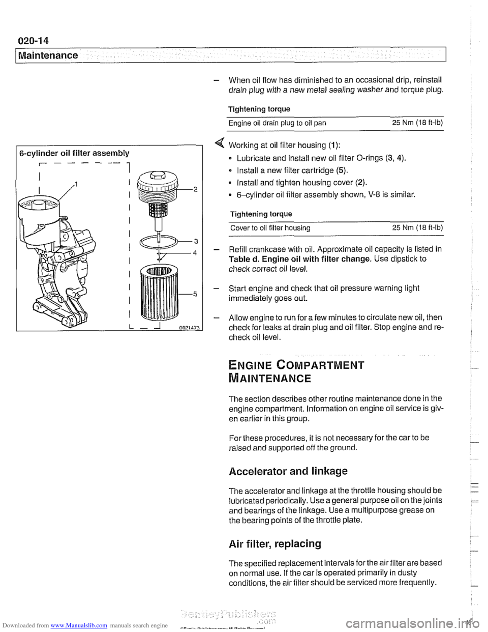
6-cylinder oil filter assembly
r------ 1
< Working at oil filter housing (1):
Lubricate and install new oil filter O-rings (3, 4).
Install a new filter cartridge (5).
lnstall and tighten housing cover (2).
6-cylinder oil filter assembly shown, V-8 is similar.
Tightening torque Cover to oil filter housing
25 Nm (1.8 it-lb)
- Refill crankcase with oil. Approximate oil capacity is listed in
Tabled. Engine oil with filter change. Use dipstick to
check correct oil level.
- Start engine and check that oil pressure warning light
immediately goes out.
- Allow engine to run fora few minutes to circulate new oil, then
check for leaks at drain plug and oil filter. Stop engine and re-
check oil level
The section describes other routine maintenance done in the
engine compartment. Information on engine oil service is
giv-
enkar~ier inthis group.
For these procedures, it is not necessary for the car to be
raised and supported off the ground.
Accelerator and linkage
The accelerator and linkage at the throttle housing should be
lubricated periodically. Use ageneral purposeoil on the joints
and bearings of the linkage. Use a multipurpose grease on
the bearing points of the throttle plate.
Air filter, replacing
The specified replacement intervals forthe air filter are based
on normal use. If the car is operated primarily in dusty
conditions, the air filter should be serviced more frequently.
Page 69 of 1002
Downloaded from www.Manualslib.com manuals search engine
Engine identifying features
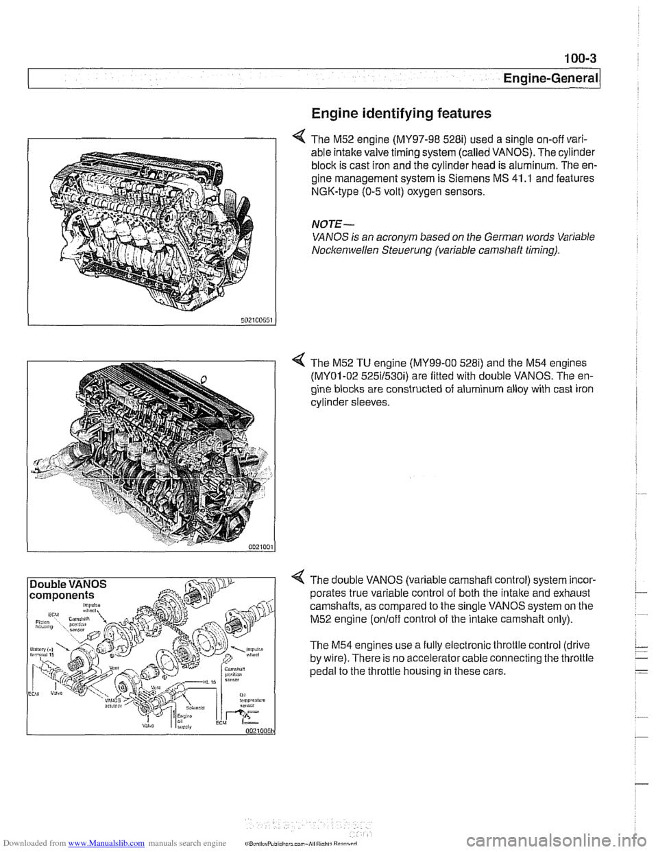
4 The M52 engine (MY97-98 528i) used a single on-off vari-
able intake valve timing system (called VANOS). The cylinder
block is cast iron and the cylinder head is aluminum. The en-
gine management system is Siemens MS 41
.I and features
NGK-type (0-5 volt) oxygen sensors.
NOTE-
VANOS is an acronym based on the German words Variable
Nocltenwellen Steuerung (variable camshaft timing).
4 The M52 TU engine (MY99-00 5281) and the M54 engines
(MY01-02 525il530i) are fitted with double VANOS. The en-
gine
blocits are constructed of aluminum alloy with cast iron
cylinder sleeves.
4 The double VANOS (variable camshaft control) system incor-
porates true variable control of both the
intake and exhaust
camshafts, as compared to the single VANOS system on the
M52 engine
(onloff control of the intaite camshaft only).
The M54 engines use a fully electronic throttle control (drive
by wire). There is no accelerator cable connecting the throttle
pedal to the throttle housing in these cars.
Page 70 of 1002
Downloaded from www.Manualslib.com manuals search engine
100-4
I Engine-General
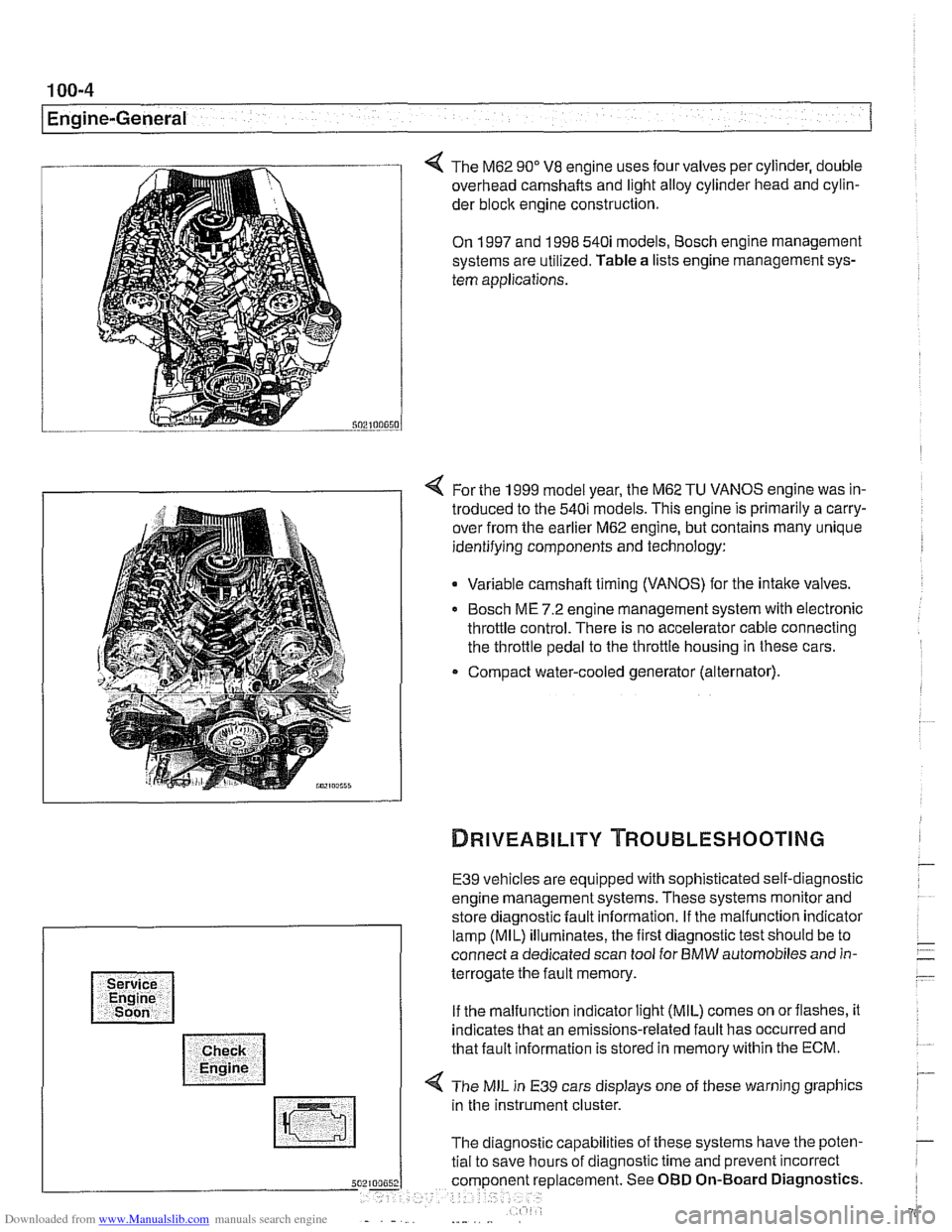
The M62 90" V8 engine uses four valves per cylinder, double
overhead camshafts and light alloy cylinder head and cylin-
der
bloclc engine construction.
On 1997 and 1998 540i models, Bosch engine management
systems are utilized. Table a lists engine management sys-
tem applications.
4 For the 1999 model year, the M62 TU VANOS engine was in-
troduced to the 540i models. This engine is primarily a carry-
over from the earlier M62 engine, but contains many unique
identifying components and technology:
Variable camshaft timing (VANOS) for the intake valves.
Bosch ME 7.2 engine management system with electronic
throttle control. There is no accelerator cable connecting
the throttle pedal to the throttle housing in these cars.
Compact water-cooled generator (alternator).
E39 vehicles are equipped with sophisticated self-diagnostic
engine management systems. These systems monitor and
store diagnostic fault information. If the malfunction indicator
lamp (MIL) illuminates, the first diagnostic test should be to
connect a dedicated scan tool for BMW automobiles and in-
terrogate the fault memory.
If the malfunction indicator light (MIL) comes on orflashes, it
indicates that an emissions-related fault has occurred and
that fault information is stored in memory within the ECM.
4 The MIL in E39 cars displays one of these warning graphics
in the instrument cluster.
The diagnostic capabilities of these systems have the poten-
tial to save hours of diagnostic time and prevent incorrect
5 placement. See OBD On-Board Diagnostics.
Page 76 of 1002
Downloaded from www.Manualslib.com manuals search engine
11 0-4
/Engine Removal and Installation
- Disconnect negative (-) cable from battery.
CAUTION- Prior to disconnecting the
batteg read the battery discon-
nection cautions
in 001 General Cautions and Warnings.
- Remove engine hood, or place in service position. See 410
Fenders, Engine Hood.
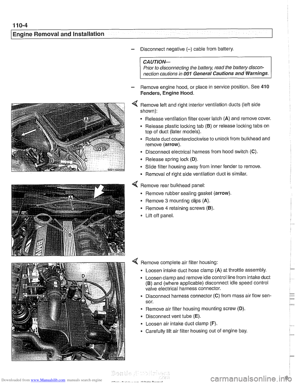
4 Remove left and right interior ventilation ducts (lefl side
shown):
Release ventilation filter cover latch (A) and remove cover.
Release plastic loclting tab
(6) or release locking tabs on
top of duct (later models).
Rotate duct counterclocltwise to
unloclt from bulkhead and
remove (arrow).
Disconnect electrical harness from hood switch (C).
Release spring
loclt (D).
Slide filter housing away from inner fender to remove.
Removal of right side ventilation duct is similar.
Remove rear bulkhead panel:
Remove rubber sealing gasket (arrow).
- Remove 3 mounting clips (A).
Remove
4 retaining screws (6).
Lift off panel.
Remove complete air filter housing:
Loosen
intalte duct hose clamp (A) at throttle assembly.
Loosen clamp and remove idle control line from intalte duct
(6) and (where applicable) disconnect idle speed control
valve electrical harness connector.
Disconnect harness connector (C) from mass air flow sen-
sor.
Remove air filter housing mounting screw (D).
Disconnect vent tube
(E).
Loosen air intake duct clamp (F).
Carefully lift air filter housing out of engine bay.
Page 77 of 1002
Downloaded from www.Manualslib.com manuals search engine
Engine Removal and lnstallationl
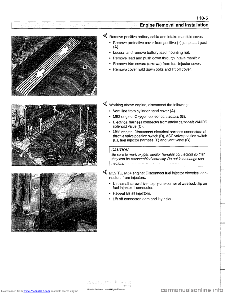
< Remove positive battery cable and intake manifold cover:
Remove protective cover from positive (+)jump start post
(4.
Loosen and remove battery lead mounting nut.
Remove lead and push down through intake manifold
Remove trim covers
(arrows) from fuel injector cover.
Remove cover hold down bolts and lift off cover.
Working above engine, disconnect the following:
Vent line from cylinder head cover (A).
M52 engine: Oxygen sensor connectors (8).
Electrical harness connector from intalte camshaft VANOS
solenoid valve
(C).
M52 engine: Disconnect electrical harness connectors at
throttle valve position switch
(D), ASC valve position switch
(E), fuel injector harness (F) and vent valve (G).
CAUTION-
Be sure to mark oxygen sensor harness connectors so that
they can be reassembled correctly Do not interchange con-
nectors.
4 M52 TU, M54 engine: Disconnect fuel injector electrical con-
nectors from injectors.
Use small screwdriverto pry one corner of wire lock clip on
fuel injector
1 connector.
Repeat for all injectors.
Lifl off connector loom and lay aside.
Page 79 of 1002
Downloaded from www.Manualslib.com manuals search engine
Engine Removal and lnstallationl
NOTE-
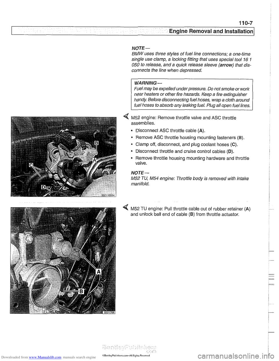
BMW uses three styles of fuel line connections; a one-time
single use clamp, a locking fitting that uses special tool
16 1
050 to release, and a quick release sleeve (arrow) that dis-
connects the line when depressed.
WARNING-
Fuel may be expelled under pressure. Do not smoke or work
near heaters or other fire hazards. Keep a fire extinguisher
handy Before disconnecting fuel hoses, wrap a cloth around
fuel hoses to absorb any leaking fuel. Plug all
oDen fuel lines.
< M52 engine: Remove throttle valve and ASC throttle
assemblies.
Disconnect ASC throttle cable
(A).
Remove ASC throttle housing mounting fasteners (El).
Clamp off, disconnect, and plug coolant hoses (C).
Disconnect throttle and cruise control cables (D).
Remove throttle housing mounting hardware and throttle
valve.
NOTE-
M52 TU, M54 engine: Throttle body is removed with intake
manifold.
< M52 TU engine: Pull throttle cable out of rubber retainer (A)
and unloclc ball end of cable (6) from throttle actuator.
Page 80 of 1002
Downloaded from www.Manualslib.com manuals search engine
110-8
1 Engine Removal and Installation
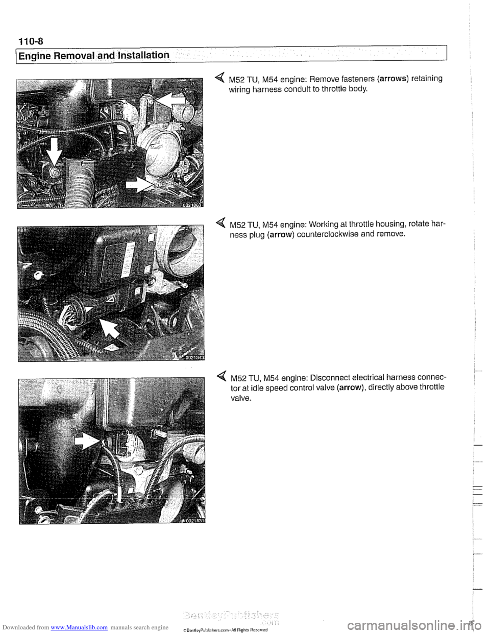
4 M52 TU, M54 engine: Remove fasteners (arrows) retaining
wiring harness conduit to throttle body.
4 M52 TU, M54 engine: Working at throttle housing, rotate har-
ness plug (arrow) counterclockwise and remove.
4 M52 TU, M54 engine: Disconnect electrical harness connec-
tor at idle speed control valve (arrow), directly above throttle
valve.
Page 81 of 1002
Downloaded from www.Manualslib.com manuals search engine
Engine Removal and lnstallationl
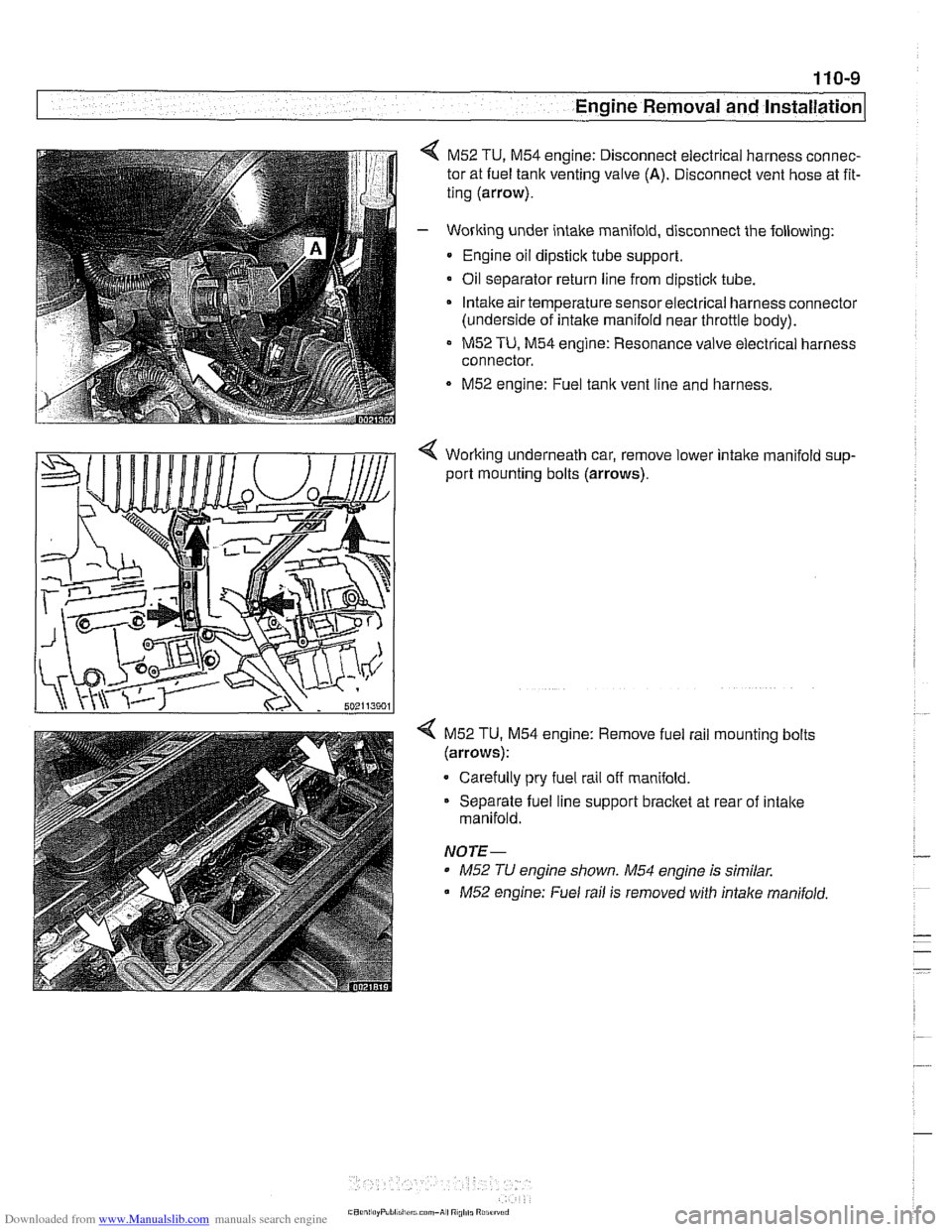
M52 TU, M54 engine: Disconnect electrical harness connec-
tor at fuel tank venting valve
(A). Disconnect vent hose at fit-
ting (arrow).
- Working under intake manifold, disconnect the following:
Engine oil dipstick tube support.
Oil separator return line from
dipsticlc tube.
Intake air temperature sensorelectrical harness connector
(underside of intake manifold near throttle body).
M52 TU, M54 engine: Resonance valve electrical harness
connector.
M52 engine: Fuel tank vent line and harness.
< Working underneath car, remove lower intalte manifold sup-
port mounting bolts (arrows).
4 M52 TU. M54 engine: Remove fuel rail mounting bolts
(arrows):
Carefully pry fuel rail off manifold.
Separate fuel line support bracket at rear of intake
manifold.
NOTE-
* M52 TU engine shown. M54 engine is similar.
M52 engine: Fuel rail is removed with intalte manifold.
Page 87 of 1002
Downloaded from www.Manualslib.com manuals search engine
110-15
Engine Removal and lnstallation
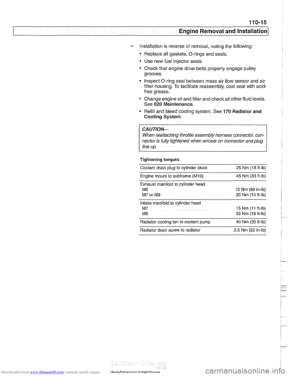
- Installation is reverse of removal, noting the following:
Replace all gaskets. O-rings and seals.
Use new fuel injector seals
Check that engine drive belts properly engage pulley
grooves.
Inspect O-ring seal between mass air flow sensor and air
filter housing. To facilitate reassembly, coat seal with acid-
free grease.
Change engine oil and filter and
check all other fluid levels.
See
020 Maintenance.
Refill and bleed cooling system. See
170 Radiator and
Cooling System.
CAUTION--
When reattaching throttle assembly harness connectoc con-
nector is
fuNy tightened when arrows on connector and plug
line up.
Tightening torques
Coolant drain plug to cylinder block
25 Nm (18 ft-lb)
Engine mount to
subframe (M10) 45 Nm (33 ft-ib)
Exhaust manifold to cylinder head
M6 10 Nm (89 in-lb)
M7 or ME 20 Nm (15 ft-lb)
Intake manifold to cylinder head
M7 15 Nm (I 1 ft-lb)
ME 22 Nm (16 ft-lb)
Radiator cooling fan to coolant pump
40 Nm (30 ft-lb)
Radiator drain screw to radiator
2.5 Nm (22 in-lb)
Page 90 of 1002
Downloaded from www.Manualslib.com manuals search engine
I Engine Removal and Installation
WARNING -
Use extreme caution when draining and disposing of engine
coolant. Coolant is poisonous andlethal to humans andpets.
Pets are attracted to coolant because of its sweet smell and
taste. Seek medical attention immediately if coolant is ingest-
---
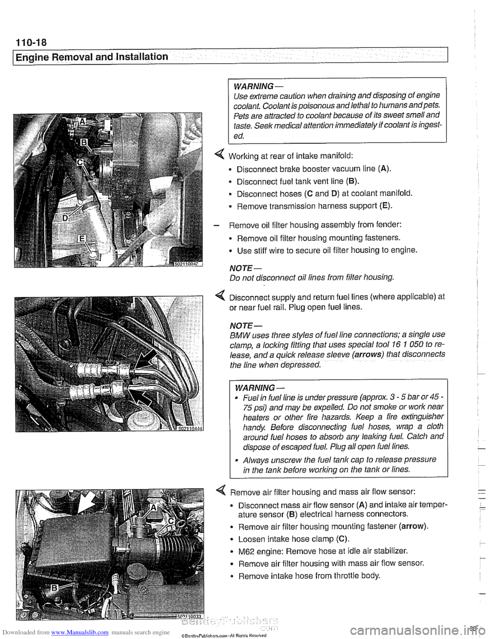
Working at rear of intake manifold:
Disconnect brake booster vacuum line (A).
Disconnect fuel tank vent line
(6).
Disconnect hoses (C and D) at coolant manifold
- Remove transmission harness support (E).
- Remove oil filter housing assembly from fender:
- Remove oil filter housing mounting fasteners.
Use stiff wire to secure oil filter housing to engine.
NOTE-
Do not disconnect oil lines from filter housing.
4 Disconnect supply and return fuel lines (where applicable) at
or near fuel rail. Plug open fuel lines.
NOTE-
BMW uses three styles of fuel line connections; a slngle use
clamp, a locking fitting that uses special tool
16 7 050 to re-
lease, and a
quiclc release sleeve (arrows) that disconnects
the line when depressed.
WARNING-
Fuel In fuel line is under pressure (approx. 3 - 5 bar or45 -
75 psi) and may be expelled. Do not smoke or worlc near
heaters or other fire hazards. Keep a fire extinguisher
handy. Before disconnecting fuel hoses, wrap a cloth
around fuel hoses to absorb any lealcing fuel. Catch and
dispose of escaped fuel. Plug all open fuel lines.
. Always unscrew the fuel tank cap to release pressure
in the tank before worlcing on the tank or lines.
< Remove air filter housing and mass air flow sensor:
Disconnect mass air flow sensor (A) and
intalte air temper-
ature sensor
(6) electrical harness connectors.
. Remove air filter housing mounting fastener (arrow).
Loosen intake hose clamp (C).
M62 engine: Remove hose at idle air stabilizer.
Remove air filter housing with mass air flow sensor.
Remove intalte hose from throttle body.