Throttle BMW 525i 2001 E39 Manual PDF
[x] Cancel search | Manufacturer: BMW, Model Year: 2001, Model line: 525i, Model: BMW 525i 2001 E39Pages: 1002
Page 978 of 1002
Downloaded from www.Manualslib.com manuals search engine
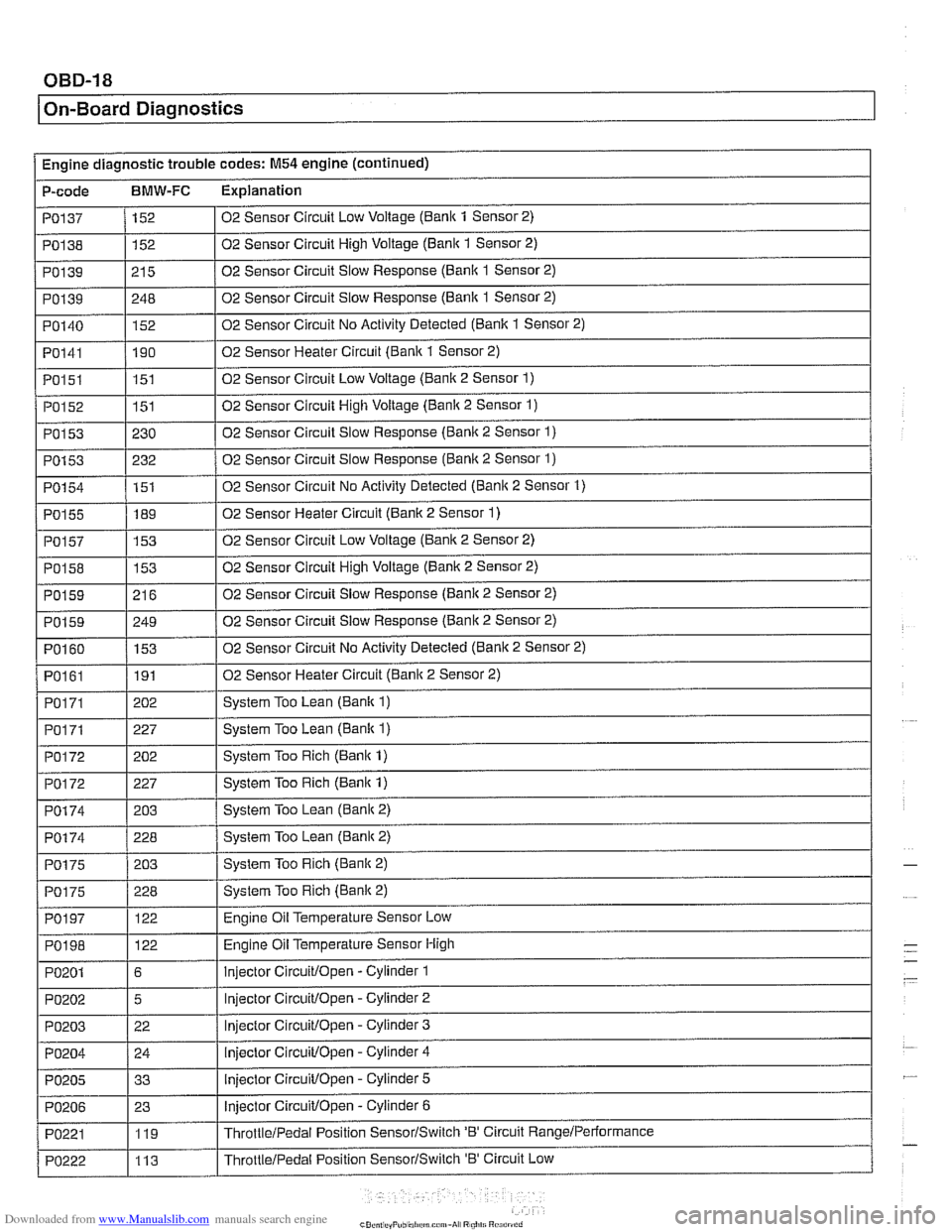
/ On-Board Diagnostics
Po202
PO203
PO204
PO205
PO206
PO221
PO222
5
22 24
33
23 119
113 Injector CircuiVOpen -Cylinder
2
Injector
CircuiVOpen -Cylinder 3
lnjeclor CircuiVOpen -Cylinder 4
Injector
CircuiVOpen - Cylinder 5
Injector CircuiVOpen - Cylinder 6
ThrotileiPedal Position SensorISwiich 'B' Circuit RangeIPeriormance
ThrottleIPedal Position SensorISwitch 'B' Circuit Low
Page 979 of 1002
Downloaded from www.Manualslib.com manuals search engine
On-Board ~ia~nosticsl
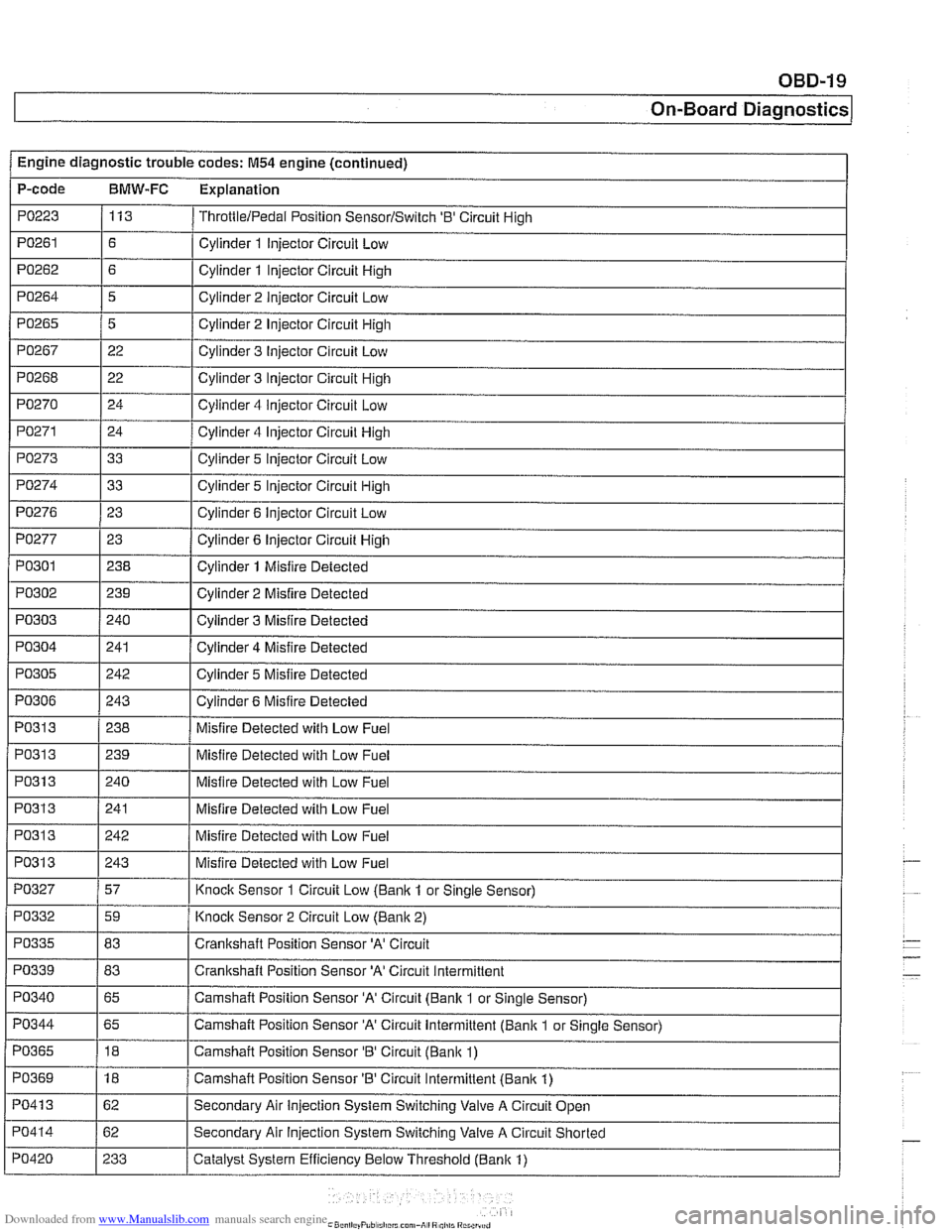
Engine diagnostic trouble codes: M54 engine (continued) I -.
P-code BMW-FC Explanation
PO223 113 ThrottlelPedal Position SensorlSwitch '0' Circuit High
PO261 / Cylinder 1 Injector Circuit Low
PO271 Cylinder 4 Injector Circuit High
PO273 Cylinder 5 Injector Circuit Low
Cylinder 2 Injector Circuit High
Cylinder 3 Injector Circuit
Low
Cylinder 3 Injector Circuit High
Cylinder 4
iniector Circuit Low
PO265
PO267
PO268
PO270
, I
PO277 1 23 1 Cylinder 6 Injector Circuit High
5
22
22
24
I I
PO274
PO301
PO302
PO303
PO304
PO276 1 23 I Cylinder 6 Injector Circuit Low
33
I
I -
I I
PO31 3 1 240 I Misfire Detected with Low Fuel Cylinder 5 Injector Circuit High
238
239
240
241
PO305
I I
Cylinder 1 Misfire Detected
Cylinder 2 Misfire Detected
Cylinder 3 Misfire Detected
Cylinder 4 Misfire Detected
PO313
PO306 1 243 I Cylinder 6 Misfire Detected
242
PO313
PO313
PO31 3
PO327
Cylinder 5 Misfire
Detected
PO31 3 1239 I Misfire Detected with Low Fuel
238
PO332
PO335
PO339 - PO340
Misfire Detected with Low Fuel
241
242
243
57
PO344
PO365
PO369
PO41 3
PO414
PO420
Misfire Detected with Low Fuel
Misfire Detected with Low Fuel
Misfire Detected with Low Fuel
Knock Sensor 1 Circuit Low
(Banlc 1 or Sinale Sensor)
59
83
83
65
-
Knoclc Sensor 2 Circuit Low (Banlc 2)
Crankshaft Position Sensor
'A' Circuit
Crankshaft Position Sensor
'A' Circuit Intermittent
Camshaft Position Sensor 'A' Circuit (Bank 1 or Single Sensor)
65
18
18
62
62
233 Camshaft Position Sensor
'A' Circuit Intermittent (Bank 1
or Single Sensor)
Camshaft Position Sensor
'B' Circuit (Banlc 1)
Camshaft Position Sensor 'B' Circuit Intermittent (Bank 1)
Secondary Air Injection System Switching Valve A Circuit Open
Secondary Air
Injection System Switching Valve A Circuit Shorted
Catalyst System Efficiency Below Threshold (Bank 1)
Page 983 of 1002
![BMW 525i 2001 E39 Manual PDF Downloaded from www.Manualslib.com manuals search engine
OBD-23
On-Board ~iagnostics]
I I
PI625 / 147 I Pedal Position Sensor Potentiometer Supply Channel 2 Electrical 1
Engine diagnostic troubl BMW 525i 2001 E39 Manual PDF Downloaded from www.Manualslib.com manuals search engine
OBD-23
On-Board ~iagnostics]
I I
PI625 / 147 I Pedal Position Sensor Potentiometer Supply Channel 2 Electrical 1
Engine diagnostic troubl](/img/1/2822/w960_2822-982.png)
Downloaded from www.Manualslib.com manuals search engine
OBD-23
On-Board ~iagnostics]
I I
PI625 / 147 I Pedal Position Sensor Potentiometer Supply Channel 2 Electrical 1
Engine diagnostic trouble codes: M54 engine (continued)
P-code
BMW-FC Explanation
PI 604
PI604
PI619
PI620
PI624
PI632
PI633
PI634
P1 634
PI 634
PI 635
PI 636 50
51 123
123
146 i I
I
I Barometric Pressure Circuit Low
Control
Module Self-Test,
Speed Monitoring
Control Module Self-Test, Speed Monitoring
Map Cooling Thermostat Control Circuit Signal Low
Map Cooling Thermostat Control Circuit Signal High Pedal Position Sensor Potentiometer Supply Channel
1 Electrical (M52: Coolant Thermostat (Coolant
Temperature Below Thermostat Regulating Temperature))
115
115
115
135
136
115
109
PI639
PI675
PI694
P2088
P2089
P2090
P2091
I I
P2229 1197 I Barometric Pressure Circuit High
Throttle
Valve Adaptation Conditions Not Met
Throttle
Valve Adaptation Limp-Home Position Unknown
Throttle Valve Adaptation Spring Test Failed
Throttle
Valve Adaptation Spring Test Failed
Throttle
Valve Adaptation Spring Test Failed
Throttle Valve Adaptation Lower Mechanical Stop not Adapted
Throttle Valve Control Circuit
Throttle Valve Position Control, Control Deviation
PI 637
I I
P2270 1215 1 02 Sensor Signal Stuck Lean (Banic 1 Sensor 2)
PI 638 1160 I Throttle Valve Position Control Throttle Stucic Temporarily
162
161
135
136
21
21 19
19 Throttle
Valve Position Control Throttle
Stucic Permanently
Throttle Valve Actuator Start Test Re-Adaptation Required
Throttle Valve Actuator Start Test Spring Test and Limp-Home Position Failed
'A' Camshaft Position Actuator Control Circuit Low (Banlc 1)
'A' Camshaft Position Actuator Control Circuit High (Banlc 1)
'B' Camshaft Position Actuator Control Circuit Low (Bank 1)
'B' Camshaft Position Actuator Control Circuit High (Bank 1)
P2271
P2272
P2273
P3041
P3198 I I -
215
216
21 6
10481
10205 02
Sensor Signal Stucic Lean (Bank 1 Sensor 2)
02 Sensor Signal
Stuclc Lean (Bank 2 Sensor 2)
02 Sensor Signal Stuclc Lean (Bank 2 Sensor 2)
02 Sensor Lean and Rich Voltage Thresholds not Reached (Bank 2 Sensor 2)
Engine Coolant Temperature Gradient Too High
Engine Coolant Temperature Signal Stuck
P3199
P3238 1 10289 I Control Module Monitoring TPU Chip Defective
10207
Page 984 of 1002
Downloaded from www.Manualslib.com manuals search engine
/ On-Board Diaanostics I
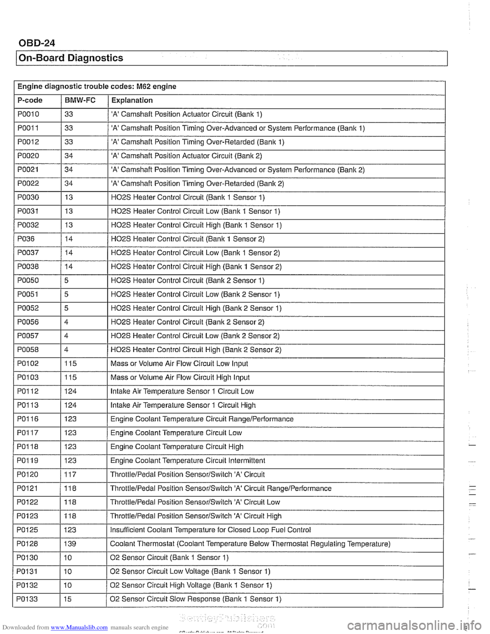
Engine diagnostic trouble codes: M62 engine
P-code
PO01 1
PO012
PO020
PO021
PO022
PO030
PO031
PO032
I I
PO038 / 14 I H02S Heater Control Circuit High (Bank 1 Sensor 2)
PO010 / 33 / 'A' Camshaft Position Actuator Circuit (Bank 1)
BMW-FC
I I -.
Explanation
33
33
34
34
34 13
13
13
PO36
'A' Camshaft Position Timing Over-Advanced or System Performance (Bank 1)
'A' Camshaft Position Timing Over-Retarded (Bank 1)
'A' Camshaft Position Actuator Circuit (Bank 2)
'A' Camshaft Position Timing Over-Advanced or System Performance (Banlc 2)
'A' Camshaft Position Timing Over-Retarded (Banlc 2)
H02S Heater Control Circuit (Bank 1 Sensor 1)
H02S Heater Control Circuit Low (Bank 1 Sensor 1)
HOPS Heater Control Circuit Hiqh (Banlc 1 Sensor 1)
PO050
PO051
PO052
PO056
PO057
PO058
PO037 / 14 / H02S Heater Control Circuit Low (Bank 1 Sensor 2)
14
I I -.
Ir-1 ThrottleIPedal Position SensorISwitch 'A' Circuit
Low-
HO2S Heater Control Circuit (Bank 1 Sensor 2)
5
5
5
4
4
4
PO102
PO1 13
PO116
PO117
PO118
PO119
PO120
PO121
H02S Heater Control Circuit (Banlc 2 Sensor 1)
H02S Heater Control Circuit Low (Bank 2 Sensor 1)
H02S Heater Control Circuit High (Bank 2 Sensor 1)
H02S Heater Control Circuit (Bank 2 Sensor 2)
HO2S Heater Control Circuit Low (Bank 2 Sensor 2)
HO2S Heater Control Circuit Hiqh (Bank 2 Sensor 2)
PO103 1115 I Mass or Volume Air Flow Circuit High Input
115
124
123
123
123
123
117
118
PO1 23
PO125
PO128
PO1 30
PO131
POI 32
PO133
Mass or Volume Air Flow Circuit Low Input
lntalte Air Temperature Sensor 1 Circuit High
Engine Coolant Temperature Circuit
RangeIPerlormance
Engine Coolant Temperature Circuit Low
Engine Coolant Temperature Circuit High
Engine Coolant Temperature Circuit Intermittent
ThrottleIPedal Position SensorISwitch 'A' Circuit
ThrottieIPedal Position SensorISwitch 'A' Circuit RanqeIPerformance
118
123 139
10
10
10
15
ThrottleIPedai Position SensorlSwitch 'A' Circuit High
insufficient Coolant Temperature for Closed Loop Fuel Control
Coolant Thermostat (Coolant Temperature Below Thermostat Regulating Temperature)
02 Sensor Circuit (Bank
1 Sensor 1)
02 Sensor Circuit Low Voltage (Bank 1 Sensor 1)
02 Sensor Circuit High Voltage (Bank
1 Sensor 1)
02 Sensor Circuit Slow Response (Bank 1 Sensor
1)
Page 989 of 1002
Downloaded from www.Manualslib.com manuals search engine
On-Board ~ia~nosticsl
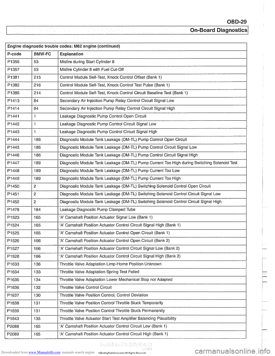
Engine diagnostic trouble codes: M62 engine (continued)
P-code
I I -
I I - -.
PI445 1186 / Diagnostic Module Tank Leakage (DM-TL) Pump Control Circuit Signal Low
PI357
PI382
PI386
PI413
PI414
PI441
PI442
PI443
PI444
P1356 1 53 I Misfire during Start Cylinder 8
BMW-FC
I P1523
I
I - -
1165 I 'A' Camshaft Position Actuator Signal Low (Banlc 1)
Explanation
P1381 1215 I Control Module Self-Test, Knock Control Onset (Bank 1)
53
21 6
21 4
84
84
1
1
1
186
PI 446
PI 447
PI 448
PI449
PI 450
PI451
PI452
PI476
Misfire Cylinder 8 with Fuel Cut-Off
Control Module Self-Test, Knock Control Test Pulse (Bank 1)
Control Module Self-Test, Knock Control Circuit Baseline Test (Bank 1)
Secondary Air Injection Pump Relay Control Circuit Signal Low
Secondary Air Injection Pump
Relay Control Circuit Signal High
Leakage Diagnostic Pump Control Open Circuit
Leakage Diagnostic Pump Control Circuit Signal Low
Leakage Diagnostic Pump Control Circuit Signal High
Diagnostic Module Tank Leakage (DM-TL) Pump Control Open Circuit
186
189
189
189
2
2
2
184
P1524
P1525
P1526
PI527
PI528
PI633
PI 634
PI 635
I I
PI 638 / 131 I Throttle Valve Position Control Throttle Stuck Temporarily
. -
Diagnostic Module Tank Leakage (DM-TL) Pump Control Circuit Signal High
Diagnostic Module
Tank Leakage (DM-TL) Pump Current Too High during Switching Solenoid Test
Diagnostic Module Tank Leakage (DM-TL) Pump Current Too Low
Diagnostic Module
Tank Leakage (DM-TL) Pump Current Too High
Diagnostic Module Tank Leakage (DM-TL) Switching Solenoid Control Open Circuit
Diagnostic Module
Tank Leakage (DM-TL) Switching Solenoid Control Circuit Signal Low
Diagnostic Module
Tank Leakage (DM-TL) Switching Solenoid Control Circuit Signal High
Leakaqe Diaqnostic Pump Clamped Tube
I I
165
165
166
166
166
136
133
134
'A' Camshaft Position Actuator Control Circuit Signal High (Banlc 1)
'A' Camshaft Position Actuator Control Open Circuit (Bank 1)
'A' Camshaft Position Actuator Control Open Circuit (Bank 2)
'A' Camshaft Position Actuator Control Circuit Signal Low (Bank 2)
'A' Camshaft Position Actuator Control Circuit Signal High (Bank 2)
Throttle Valve Adaptation Limp-Home Position Unknown
Throttle Valve Adaptation Spring Test Failed
Throttle Valve Adaptation Lower Mechanical Stop not Adapted
Throttle Valve Control Circuit
PI 636
PI639
P1643
P2088
P2089
PI 637 / 130 I Throttle Valve Position Control, Control Deviation
132
131
135
165
165 Throttle
Valve Position Control Thronle Stuck Permanently
Throttle Valve Actuator Start Test Amplifier Balancing Plausibility
'A' Camshaft Position Actuator Control Circuit Low (Banlc 1)
'A' Camshaft Position Actuator Control Circuit High (Bank 1)
Page 991 of 1002
Downloaded from www.Manualslib.com manuals search engine
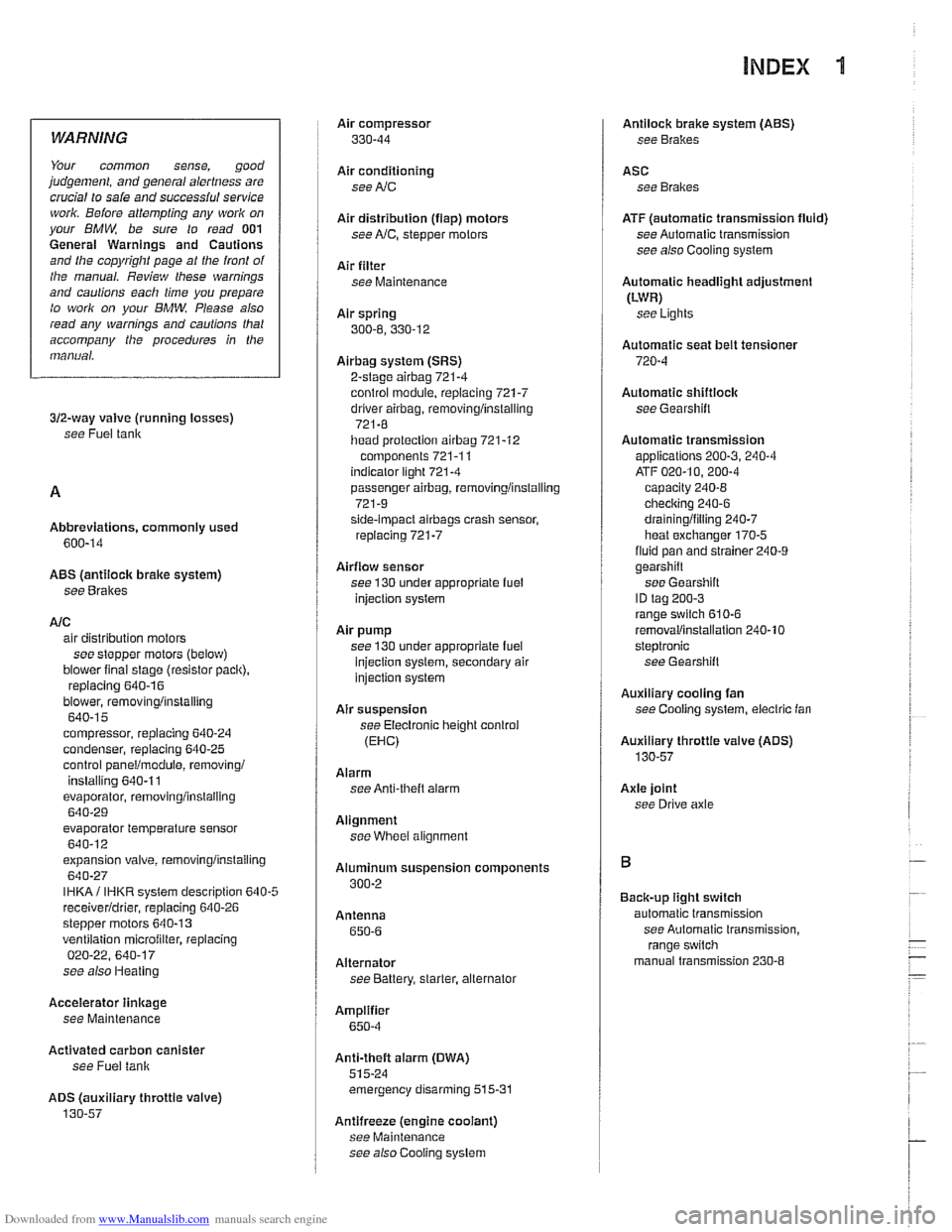
INDEX 'tl
WARNING
Your common sense, good
judgemenl, and general alertness are
crucial to sale and successiul service
worlr. Belore attempting any work on
your
BMM be sure lo read 001
General Warnings and Cautions
and the
copyriglll page at the front 01
the manual. Review these warnings
and
caulions each lime you prepare
lo work on your BMW. Please also
read any warnings and cautions that
accompany
tile procedures in the
manual.
312-way valve (running losses)
see Fuel tank
Abbreviations, commonly used 600-14
ABS (antilock brake system)
see
Bral(es
A/C air distribution motors
see stepper motors (below)
blower final stage (resistor pack),
replacing
640-16
blower, removinglinslalling
640-1 5
compressor, replacing
640-24 condenser, replacing 64045
control panellmodule, removing1
installing
640-1 1
evaporakr, removinglinstalling 640-29
evaporator temperature sensor
640-12 expansion valve, removinglinstailing
640-27
IHKA/ IHKR system description 640-5
receiveridrier, replacing 640-26
stepper motors 640-1 3 ventilation microiilter, replacing
020-22. 640-17
see also Heating
Accelerator
iinlcage
see Maintenance
Activated carbon canister
see Fuel tank
ADS (auxiliary throttle valve)
130-57
Air compressor
330-44
Air conditioning
see
AIC
Air distribution (flap) motors
seeNC, stepper motors
Air filter see Maintenance
Air spring
300-6, 330-12
Airbag system (SRS)
2-stage
airbag 721-4
control module, replacing 721-7 driver airbag, removinglinstalling
721-8
iiead protection airbag 721-12 components 721-1 1
indicator
lighl721-4
passenger airbag, removinglinstalling
721-9 side-impact airbags crash sensor,
replacing
721-7
Airflow sensor see 130 under appropriate
fuel
injection system
Air pump
see 130 under appropriate fuel
injection system, secondary air
injection system
Air suspension
see Electronic height control
(EHC)
Alarm
see Anti-theft alarm
Alignment see
Wheei alignment
Aluminum suspension components
300-2
Antenna 650-6
Alternator see Battery, starter, alte rnator
Amplifier
650-4
Anti-theft alarm (DWA)
515-24 emergency disarming 515-31
Antifreeze (engine coolant)
see Maintenance
see also Cooling system
Antilock brake system (ABS) see Brakes
ASC see Brakes
ATF (automatic transmission fluid)
see Automatic transmission
see also Cooling systern
Automatic headlight adjustmenl
(LWR) see Lights
Automatic seat belt tensioner
720-4
Automatic shiftloclc
see
Gearshift
Automatic transmission
applications
200-3, 240-4
ATF 020-10, 200-4
capacity 240-8 checking 240-6
drainingifilling 240-7
heat exchanger 170-5
fluid pan and strainer 240-9 gearshift
see Gearshift
ID tag
200-3 range switch 610-6
removaliinstallation 240-10
steptronic see Gearshift
Auxiliary cooling fan
see
Coollng system, electric Ian
Auxiliary throttle valve (ADS)
130-57
Axle joint
see Drive axle
Back-up light switch
automatic transmission see Automatic transmission. range switch
- .~.~~~
manual transmission 230-8 -
- I