Front BMW 525i 2001 E39 Workshop Manual
[x] Cancel search | Manufacturer: BMW, Model Year: 2001, Model line: 525i, Model: BMW 525i 2001 E39Pages: 1002
Page 675 of 1002
Downloaded from www.Manualslib.com manuals search engine
Steering and Wheel Alignment
Power assist is provided by a belt-driven pump at the lower
left front of the engine. The power steering fluid reservoir is lo-
cated at the left side of the engine compartment.
Power steering pump, removing and
installing
When working with power steering components, absolute
cleanliness is needed to ensure proper operation of the hy-
- Empty power steering fluid reservoir using clean syringe. Do
not reuse fluid.
- Raise front of car. Remove splash shield from under engine.
WARNING-
Make sure the car is firmly supported on jack stands de-
signed for the purpose. Place jack stands beneath structural
chassis points. Do not place jack stands under suspension
Darts.
Remove drive belt from power steering pump. See
020 Main-
tenance.
Remove alternator cooling duct
Remove fluid hoses from pump. Plug openings in pump and
hose ends.
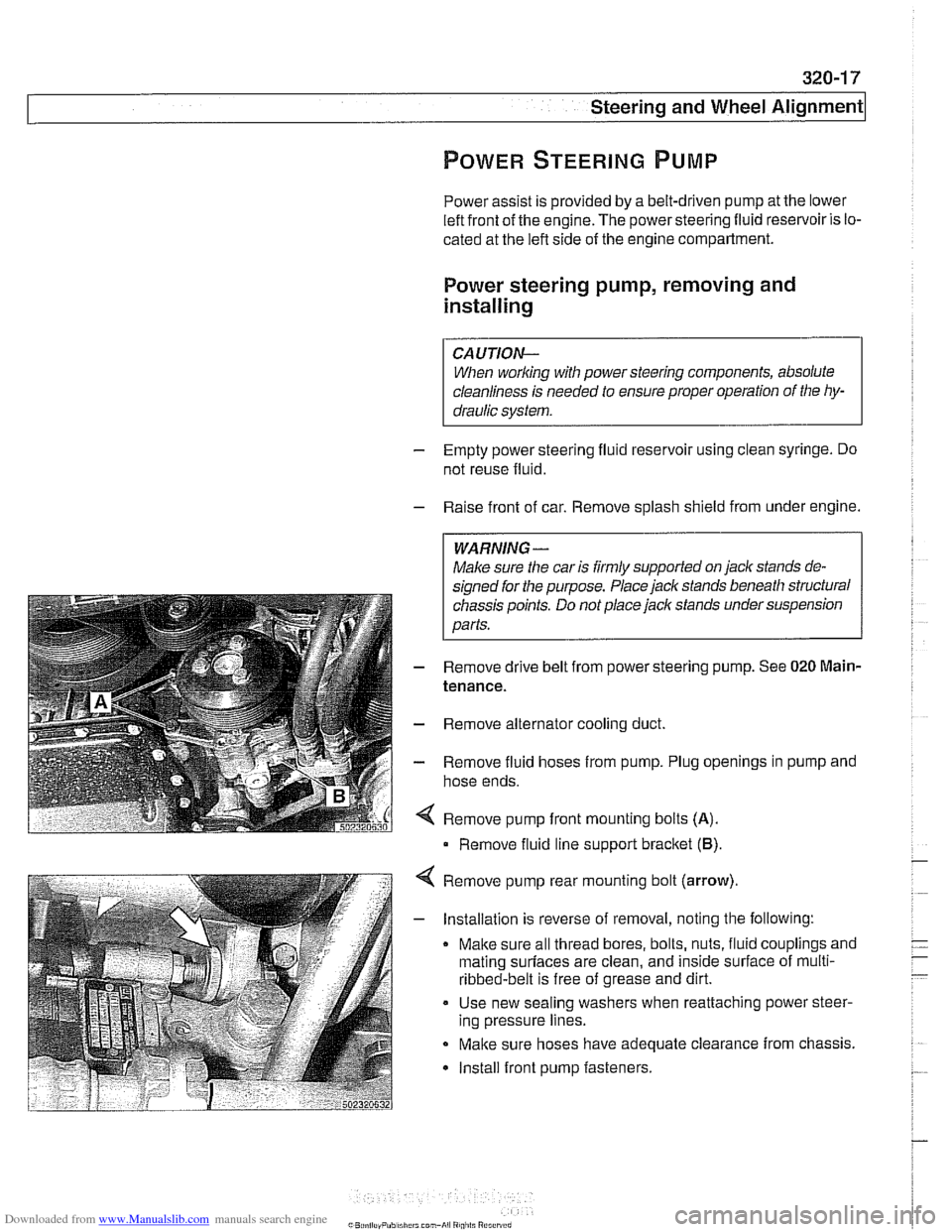
Remove pump front mounting bolts
(A).
Remove fluid line support bracket (B)
Remove pump rear mounting bolt (arrow)
- Installation is reverse of removal, noting the following:
Make sure all thread bores, bolts, nuts, fluid couplings and
mating
surfaces are clean, and inside surface of multi-
ribbed-belt is free of grease and dirt.
Use new sealing washers when reattaching power steer-
ing pressure lines.
Make sure hoses have adequate clearance from chassis.
Install front pump fasteners.
Page 677 of 1002
Downloaded from www.Manualslib.com manuals search engine
i Steering and Wheel Alignment
RACK AND PINION STEERING
(6-CYLINDER MODELS)
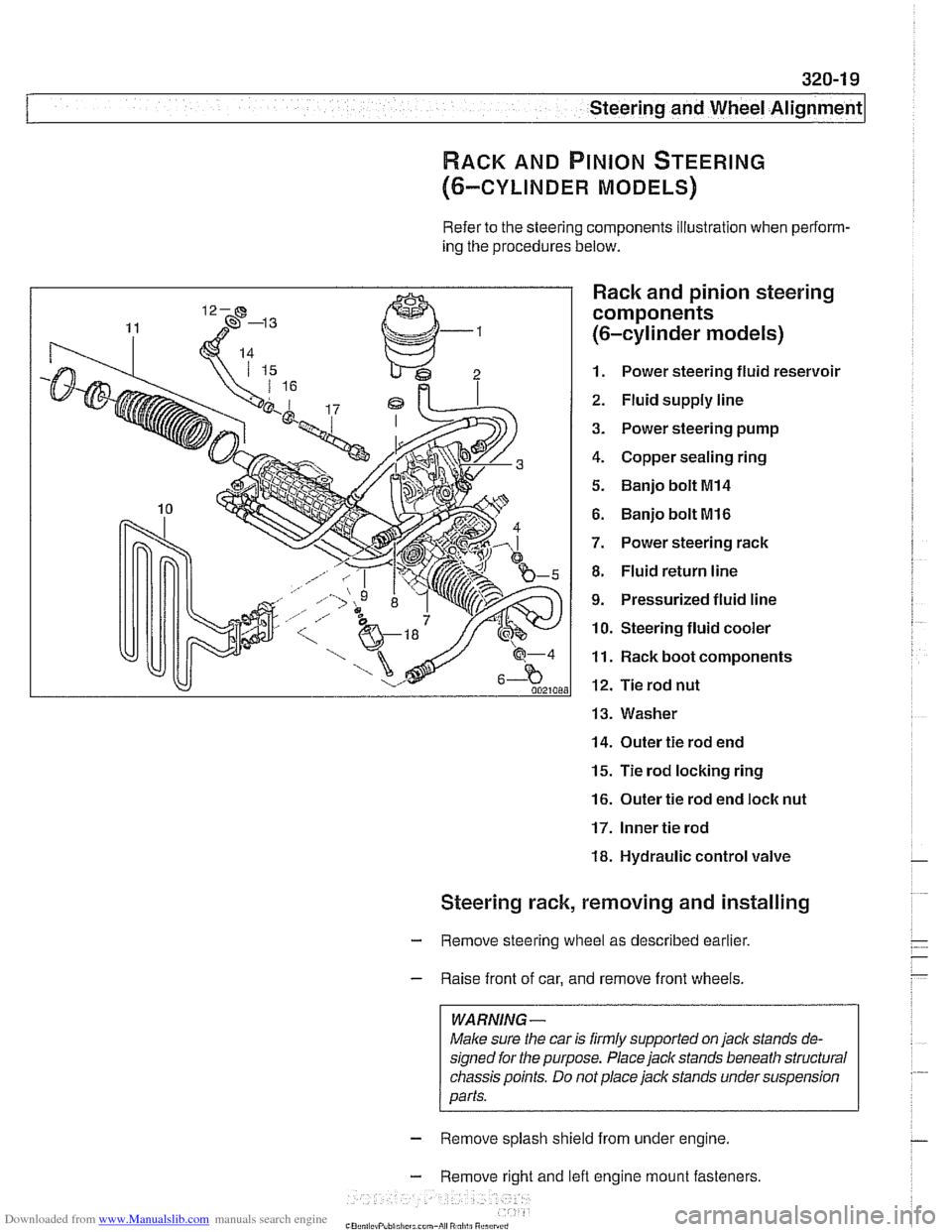
Refer to the steering components illustration when perform-
ing the procedures below.
Rack and pinion steering
components
(6-cylinder models)
1. Power steering fluid reservoir
2. Fluid supply line
3. Power steering pump
4. Copper sealing ring
5. Banjo bolt MI4
6. Banjo bolt MI6
7. Power steering rack
8. Fluid return line
9. Pressurized fluid line
10. Steering fluid cooler
11. Rack boot components
12. Tie rod nut
13. Washer
14. Outer tie rod end
15. Tie rod locking ring
16. Outer tie rod end loclc nut
17. Inner tie rod
18. Hydraulic control valve
Steering rack, removing and installing
- Remove steering wheel as described earlier.
- Raise front of car, and remove front wheels.
WARNING -
Male sure the car is firmly supported on jack stands de-
signed for the purpose. Place jack stands beneath structural
chassis points. Do
not place jack stands under suspension
parts.
- Remove splash shield from under engine.
- Remove right and lefl engine mount fasteners
-" ., - , . ,
Page 680 of 1002
Downloaded from www.Manualslib.com manuals search engine
--. --
Steering and Wheel Alignment
Steering rack boot, replacing
- Remove outer tie rod end. See Tie rod (outer), replacing
- Cut rack boot band clamps and remove boot.
- Cut rack boot band clamp and slide bellows back. Inspect
boot for any sign of damage. Replace
if necessary.
NOTE-
New rack boot lit comes with new band clamp.
- Grease tie rod taper so that small end of rack boot slides on
tie rod when tie rod is tightened, preventing raclc boot from
twisting.
- Slide new boot into position and replace band clamps
Tie rod (outer), replacing
LOCI( nut Locking ring
- Raise front of car. Remove road wheel
WARNING-
Male sure caris firmly suppoiiedon jackstands designed for
the purpose. Place jack stands beneath structural chassis
ooints. Do not olace iack stands under
susoension oaiis.
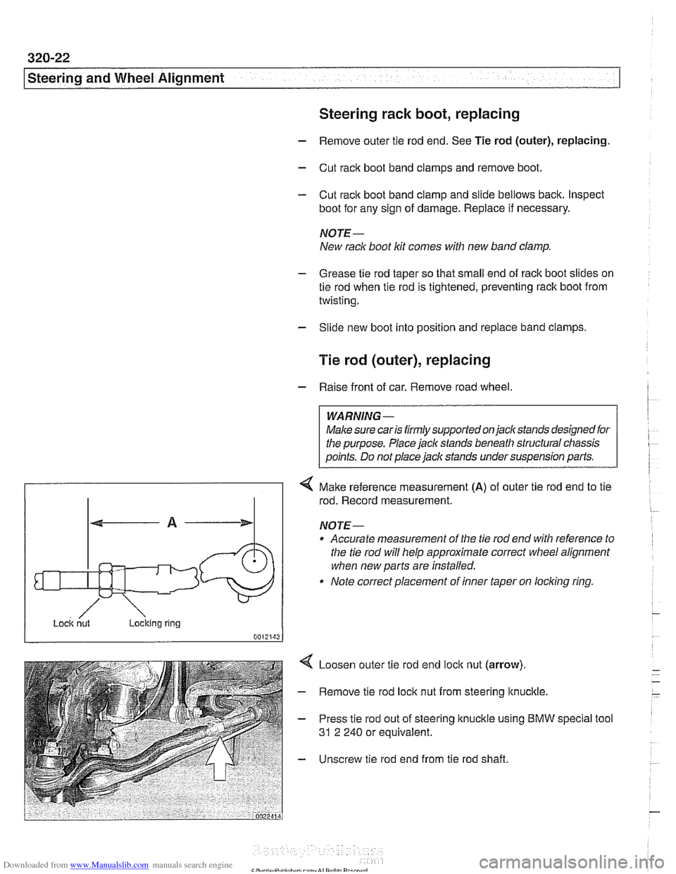
4 Make reference measurement (A) of outer tie rod end to tie
rod. Record measurement.
NOTE-
Accurate measurement of the tie rod end with reference to
the tie rod will help approximate correct
wheel alignment
when new parts are installed.
Note correct placement of inner taper on
loclcing ring.
Loosen outer tie rod end
loclc nut (arrow).
Remove tie rod lock nut from steering
ltnuclcle.
Press tie rod out of steering knuckle using BMW
31 2 240 or equivalent. special tool
Unscrew tie rod end from tie rod shaft.
Page 683 of 1002
Downloaded from www.Manualslib.com manuals search engine
Steering and Wheel ~li~nrnentl
Steering gearbox, removing and installing
- Disconnect negative (-) battery cable. See 020 Mainte-
nance.
CAUTION-
Prior to disconnecting the battew read the battery discon-
nection cautions given in
001 General Cautions and
Warnings.
- Remove airbag unit from steering wheel. See 721 Airbag
System (SRS).
WARNING -
Improper handling of the airbag could cause serious injury
Store the
airbag with the horn pad facing up. If stored lacing
down, accidental deployment couldpropel it violently info the
air, causing
injuv
- Remove steering wheel as described earlier.
- Drain power steering system reservoir.
- Raise front of car.
WARNING -
Make sure the car is firmly supported on jack stands de-
signed for the purpose. Place jack stands beneath structural
chassis points. Do not place jack stands under suspension
Darts.
- Remove heat shield from left side of subframe.
- Remove fluid hoses from top of steering gearbox. Immedi-
ately plug all fluid openings.
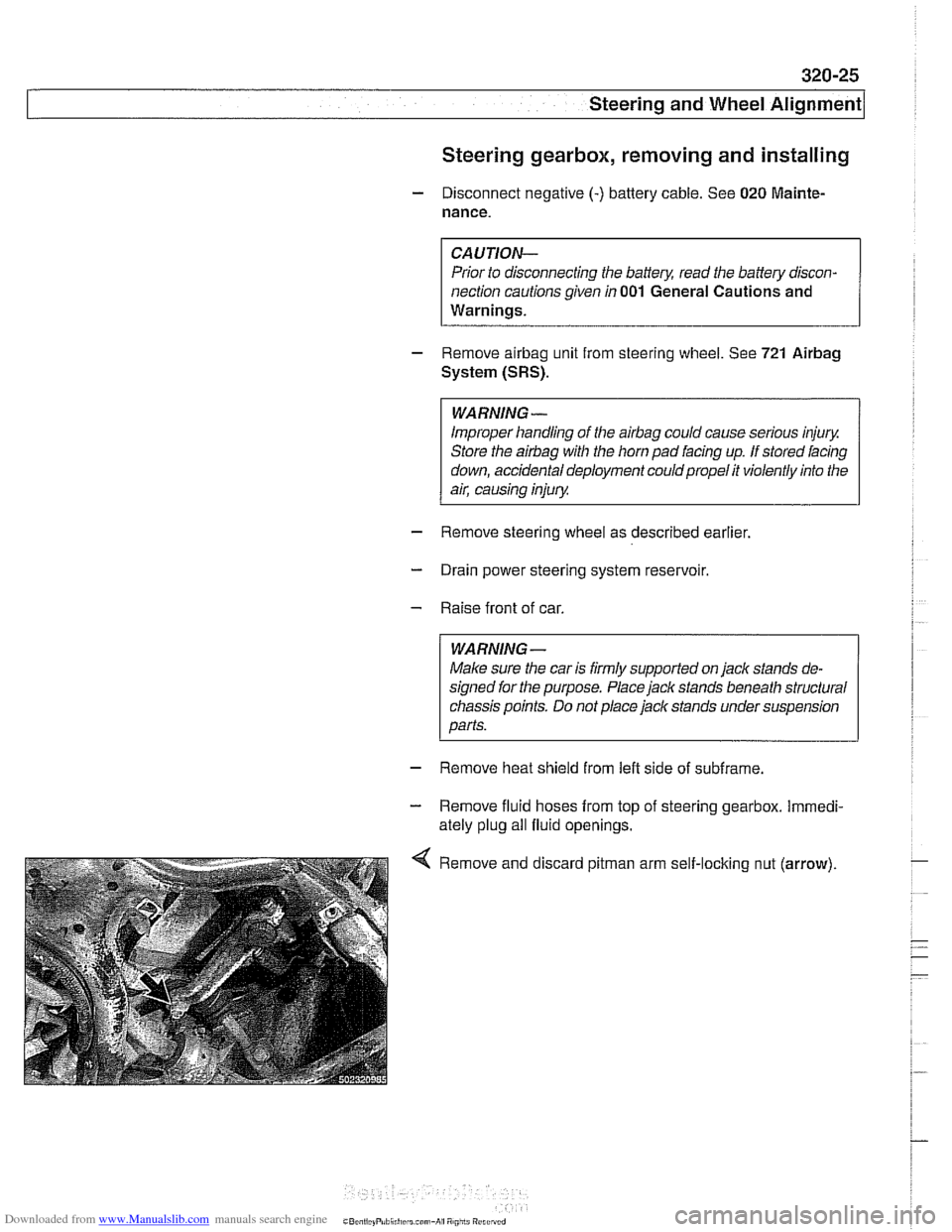
Remove and discard
pitman arm self-loclting nut (arrow).
Page 686 of 1002
Downloaded from www.Manualslib.com manuals search engine
320-28
[steering and Wheel Alignment
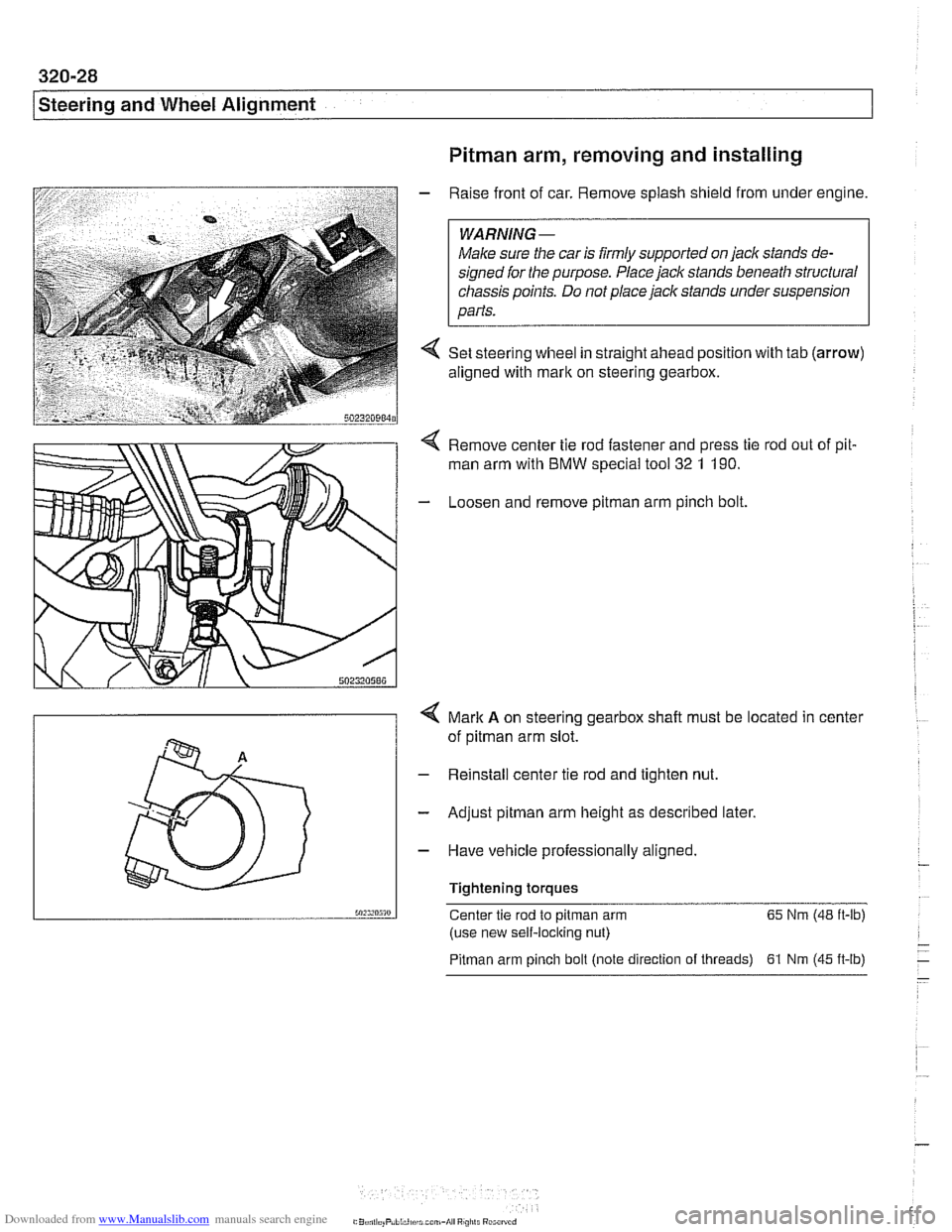
Pitman arm, removing and installing
- Raise front of car. Remove splash shield from under engine.
Male sure the car is
firmly supported on jack stands de-
signed for the purpose. Place jack stands beneath structural
chassis points. Do not place
jaclc stands under suspension
parts.
4 Set steering wheel in straight ahead position with tab (arrow)
aligned with mark on steering gearbox.
Remove center tie rod fastener and press tie rod out of pit.
man arm with BMW special
too1 32 1 190.
- Loosen and remove pitman arm pinch bolt
4 Mark A on steering gearbox shalt must be located in center
of
pitman arm slot.
- Reinstall center tie rod and tighten nut.
- Adjust pitman arm height as described later.
- Have vehicle professionally aligned.
Tightening torques
50:s,n5m Center tie rod to pitman arm 65
Nm (48 ft-lb)
(use new self-locking nut)
Pitman arm pinch bolt (note direction of threads) 61 Nrn (45 ft-lb)
Page 687 of 1002
Downloaded from www.Manualslib.com manuals search engine
Steering and Wheel Alignment
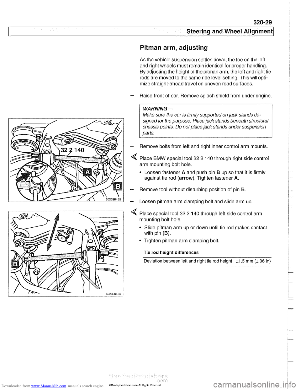
Pitman arm, adjusting
As the vehicle suspension settles down, the toe on the left
and right wheels must remain identical for proper handling.
By adjusting the height of the
pitman arm, the left and right tie
rods are moved to the same ride level setting. This will opti-
mize straight-ahead travel on uneven road surfaces.
- Raise front of car. Remove splash shield from under engine.
WARNING-
Male sure the car is iirmly supported on jack stands de-
signed ior the purpose. Place jack stands beneath structural
chassis points. Do not place
jaclc stands under suspension
parts.
- Remove bolts from left and right inner control arm mounts.
Place
BMW special tool 32 2 140 through right side control
arm mounting bolt hole.
Loosen fastener
A and push pin El up so that it is firmly
against tie rod
(arrow). Tighten fastener A.
- Remove tool without disturbing position of pin El.
- Loosen pitman arm clamping bolt and slide arm up.
4 Place special tool 32 2 140 through left side control arm
mounting bolt hole.
Slide
pitman arm up or down until tie rod makes contact
with pin
(El).
Tighten pitman arm clamping bolt.
Tie rod height differences
Deviation between
left and right tie rod height -?-I .5 rnrn (LO6 in)
Page 688 of 1002
Downloaded from www.Manualslib.com manuals search engine
I Steering and Wheel Alignment
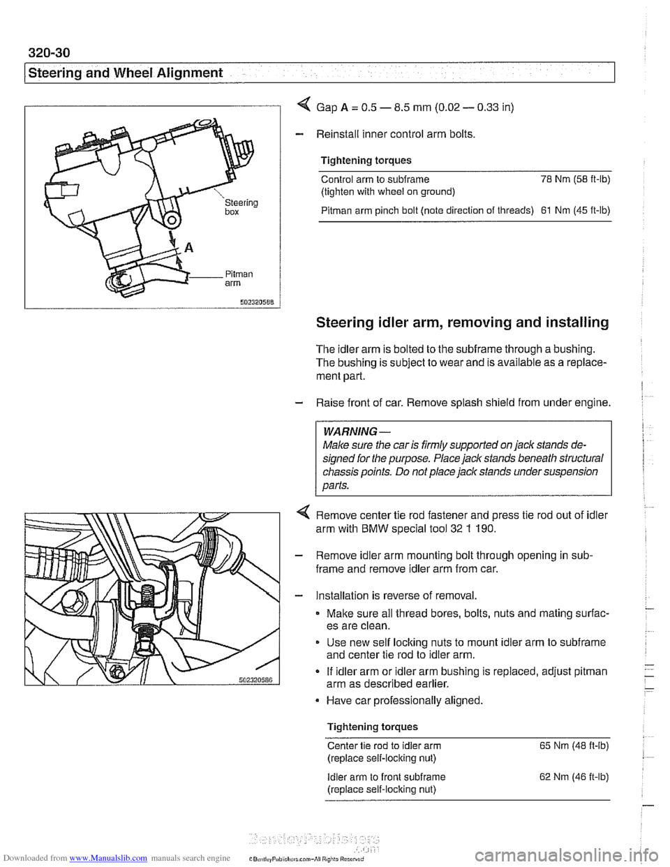
I I 4 Gap A = 0.5 - 8.5 mm (0.02 - 0.33 in)
- Reinstall inner control arm bolts
Tightening torques
Control arm to
subframe 78 Nm (58 it-lb)
(tighten with wheel on ground)
Pitman arm pinch bolt (note direction of threads) 61 Nm (45 ft-lb)
Steering idler arm, removing and installing
The idler arm is bolted to the subframe through a bushing.
The bushing is subject to wear and is available as a replace-
ment part.
- Raise front of car. Remove splash shield from under engine.
WARNING -
Male sure the car is firmly supported on jaclc stands de-
signed for the purpose. Place jack stands beneath structural
chassis points. Do not place jack stands under suspension
parts.
4 Remove center tie rod fastener and press tie rod out of idler
arm with
BMW special tool 32 1 190.
- Remove idler arm mounting bolt through opening in sub-
frame and remove idler arm from car.
- Installation is reverse of removal.
Make sure all thread bores, bolts, nuts and mating surfac-
es are clean.
Use new self
loclting nuts to mount idler arm to subframe
and center tie rod to idler arm.
If idler arm or idler arm bushing is replaced, adjust
pitman
arm as described earlier.
Have car professionally aligned.
Tightening torques
Center tie rod to idler arm 65 Nm (48 ft-ib)
(replace self-locking nut)
Idler arm to front subirame
(replace self-locking nut) 62
Nm (46 it-lb)
Page 689 of 1002
Downloaded from www.Manualslib.com manuals search engine
320-31
Steering and Wheel ~li~nrnentl
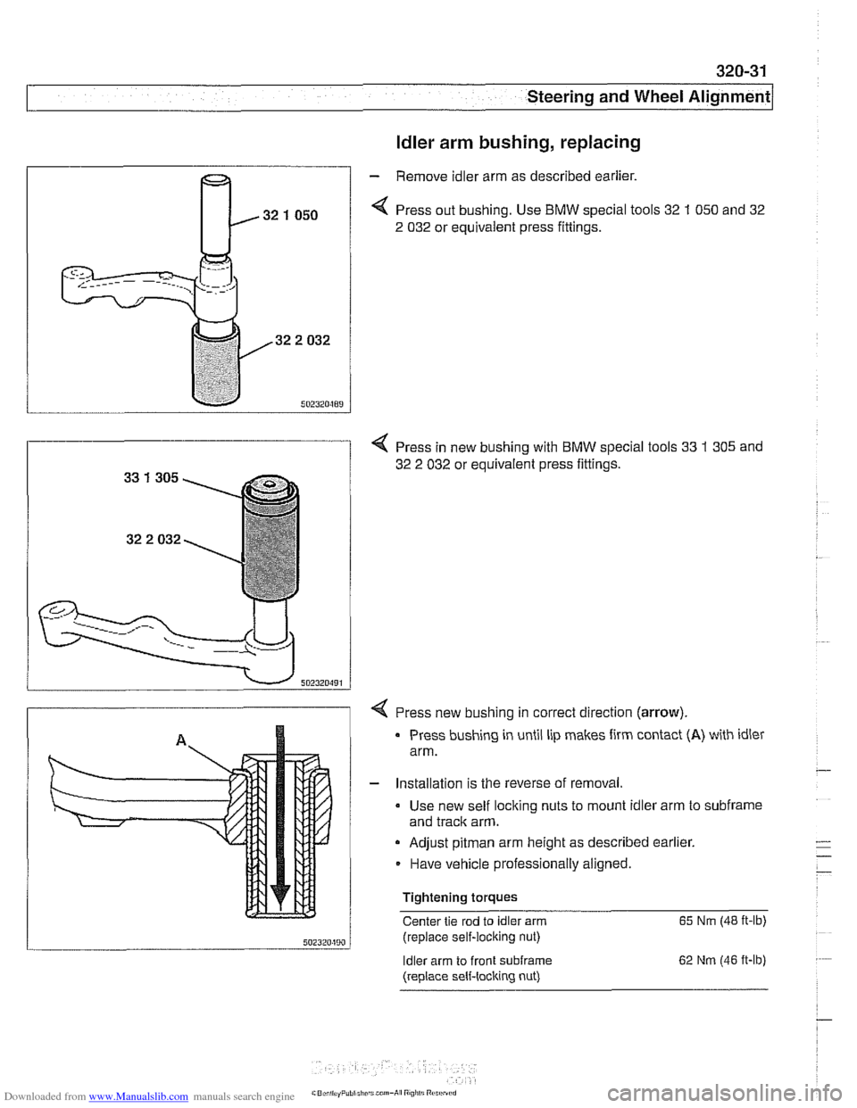
ldler arm bushing, replacing
- Remove idler arm as described earlier.
< Press out bushing. Use BMW special tools 32 1 050 and 32
2 032 or equivalent press fittings.
4 Press in new bushing with BMW special tools 33 1 305 and
32 2 032 or equivalent press fittings.
4 Press new bushing in correct direction (arrow).
u ..... "A",
Press bushing in until lip makes firm contact (A) with idler
arm.
I
Installation is the reverse of removal
Use new self locking nuts to mount idler arm to
subframe
and traclc arm.
a Adjust pitman arm height as described earlier.
Have vehicle professionally aligned.
Tightening torques Center tie rod to idler arm
65 Nm (48 ft-lb)
;nl?mmn / (replace self-locking nut)
ldler arm to front
subframe
(replace sell-locking nut) 62
Nm (46 ft-lb)
Page 690 of 1002
Downloaded from www.Manualslib.com manuals search engine
320-32
Steering and Wheel Alignment
Center tie
rod, replacing
- Raise front of car. Remove splash shield from under engine.
WARNING-
Make sure tlie car is firmly supported on jack stands de-
signed for the purpose. Place jack stands beneath structural
cliassis points. Do not place jack stands under suspension
parts.
- Measure length of left and right (outer) tie rods. Write down
measurements.
NOTE-
Accurate measurement of the tie rod end with reference to
the center tie rod will help approximate correct wheel align-
ment when new parts are installed.
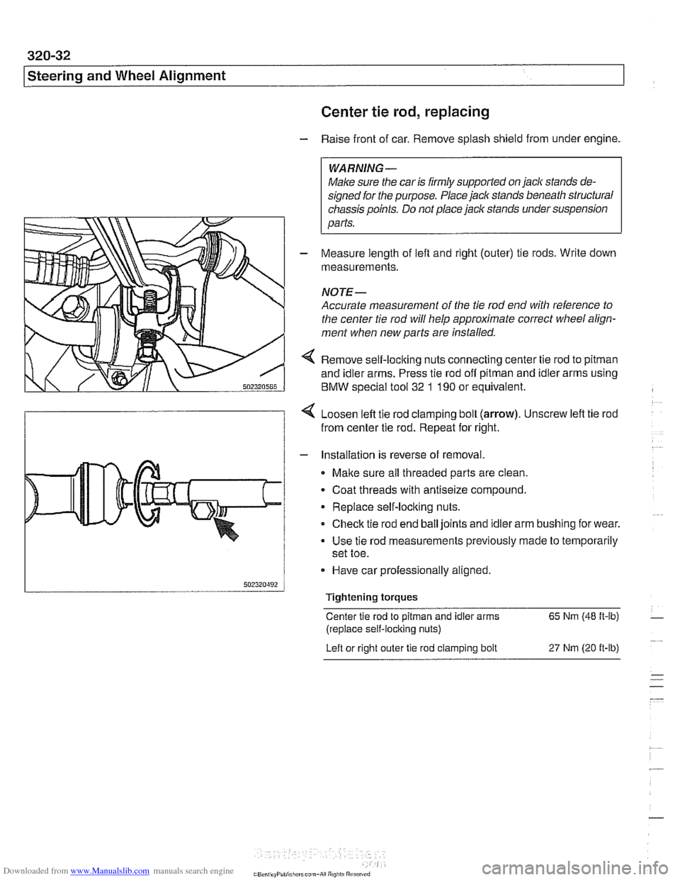
4 Remove self-loclting nuts connecting center tie rod to pitman
and idler arms. Press tie rod off pitman and idler arms using
BMW special tool
32 1 190 or equivalent.
4 Loosen left tie rod clamping bolt (arrow). Unscrew left tie rod
from center tie rod. Repeat for right.
- Installation is reverse of removal.
Malte sure all threaded parts are clean.
. Coat threads with antiseize compound.
Replace self-loclting nuts.
Check tie rod end ball joints and idler arm bushing for wear.
Use tie rod measurements previously made to temporarily
set toe.
- Have car professionally aligned.
Tightening torques
Center tie rod to
pitman and idler arms 65 Nm (48 ft-lb)
(replace self-locking nuts)
Left or right outer
tie rod clamping bolt 27 Nm (20 it-lb)
Page 691 of 1002
Downloaded from www.Manualslib.com manuals search engine
Steerina and Wheel ~lianmentl
Proper handling, stability and driving ease depend upon the
correct alignment of all four wheels. The front axle is aligned
in relation to the rear axle, then the front wheels are aligned in
relation to one another. This is known as a four-wheel or
thrust-axis alignment.
Front and rear alignment specification are given in tables at
the end of this repair group.
BMW E39 cars use a sophisticated multi-link suspension at
the front and rear of the car. Proper alignment requires com-
puterized alignment equipment.
Camber
Front wheel camber is set at the factory and cannot be adjust-
ed. Rear wheel camber is fully adjustable.
Always set rear camber before adjusting toe
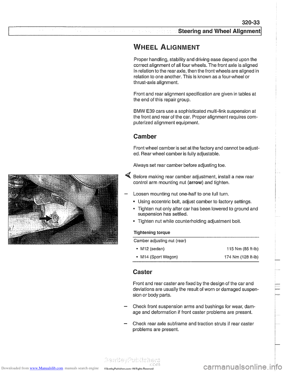
Before making rear camber adjustment, install a new rear
control arm mounting nut
(arrow) and tighten.
- Loosen mounting nut one-half to one full turn.
Using eccentric bolt, adjust camber to factory settings.
Tighten nut only after car has been lowered to ground and
suspension has settled.
Tighten nut while counterholding adjustment bolt.
Tightening torque
Camber adjusting nut (rear)
MI2 (sedan)
- MI4 (Sport Wagon)
115 Nm (85 ft-lb)
174 Nm (128 ft-lb)
Caster
Front and rear caster are fixed by the design of the car and
deviations are usually the result of worn or damaged suspen-
sion or body parts.
- Check front suspension arms and bushings for wear, dam-
age and deformation if front caster problems are present.
- Check rear axle subfrarne and traction struts if rear caster
problems are present.