break BMW 525i 2001 E39 User Guide
[x] Cancel search | Manufacturer: BMW, Model Year: 2001, Model line: 525i, Model: BMW 525i 2001 E39Pages: 1002
Page 399 of 1002
Downloaded from www.Manualslib.com manuals search engine
Fuel Injection I
Mass air flow (MAF) sensor,
checking and replacing
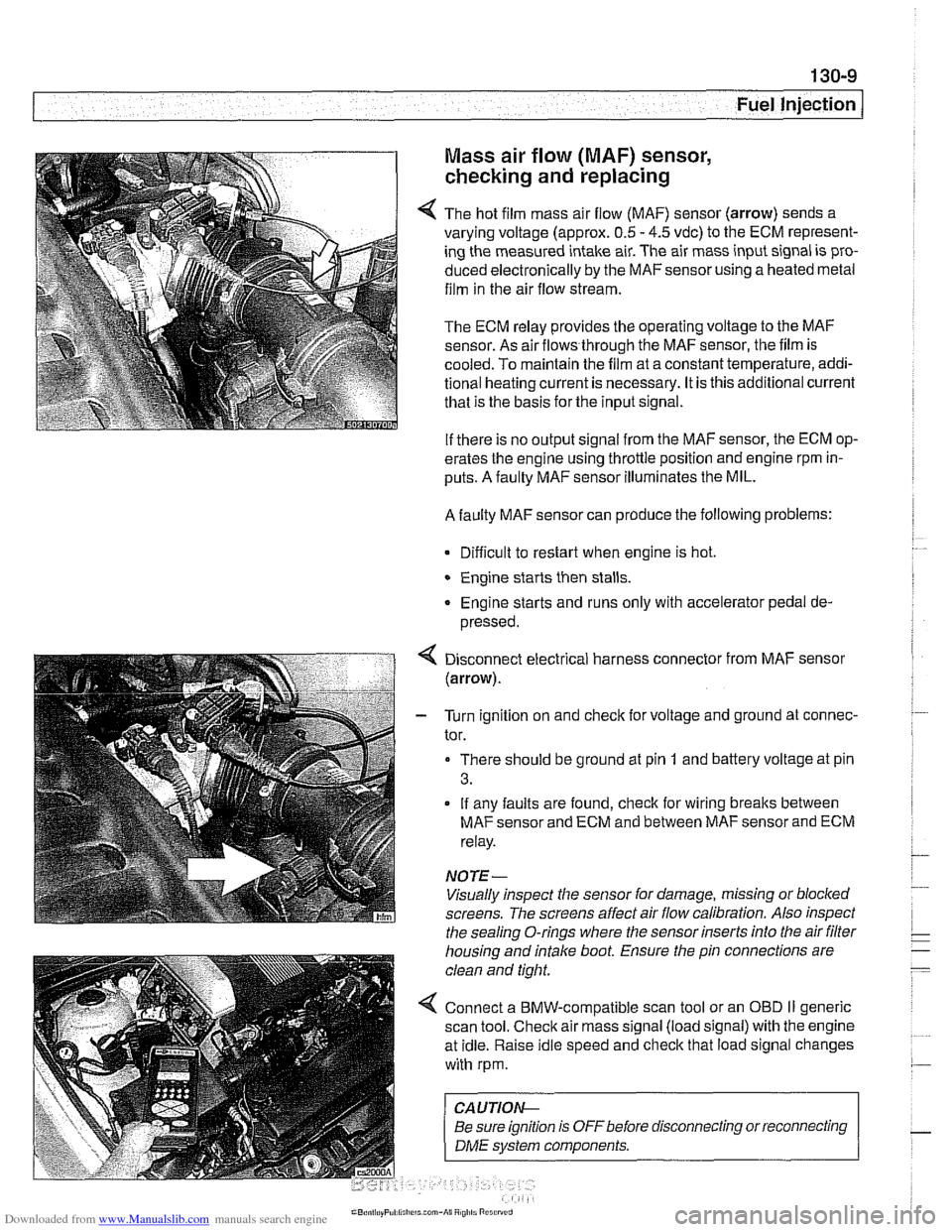
4 The hot film mass air flow (MAF) sensor (arrow) sends a
varying voltage (approx.
0.5 - 4.5 vdc) to the ECM represent-
ing the measured intake air. The air mass input signal is pro-
duced electronically by the
MAFsensorusing a heated metal
film in the air flow stream.
The ECM relay provides the operating voltage to the MAF
sensor. As air flows through the MAF sensor, the film is
-
cooled. To maintain the film at a constant temperature, addi-
tional heating current is necessary. It is this additional current
that is the basis for the input signal.
If there is no output signal from the MAF sensor, the ECM op-
erates the engine using throttle position and engine rpm in-
puts. A faulty MAF sensor illuminates the MIL.
A faulty MAF sensor can produce the following problems:
Difficult to restart when engine is hot.
Engine starts then stalls.
Engine starts and runs only with accelerator pedal de-
pressed.
Disconnect electrical harness connector from MAF sensor
(arrow).
- Turn ignition on and check for voltage and ground at connec-
tor.
There should be ground at pin
1 and battery voltage at pin
3.
If any faults are found, check for wiring breaks between
MAF sensor and ECM and between MAF sensor and ECM
relay.
NOTE-
Visually inspect the sensor for damage, missing or blocked
screens. The screens affect air flow calibration. Also inspect
the sealing O-rings where the sensor inserts into the air
filter
housing and intake boot. Ensure the pin connections are
clean and tight.
4 Connect a BMW-compatible scan tool or an OBD II generic
scan tool. Check air mass signal (load signal) with the engine
at idle. Raise idle speed and check that load signal changes
with rpm.
CA UTIOI\C
Be sure ignition is OFFbefore disconnecting or reconnecting r
1 DME svstem components. 1
Page 408 of 1002
Downloaded from www.Manualslib.com manuals search engine
130-1 8
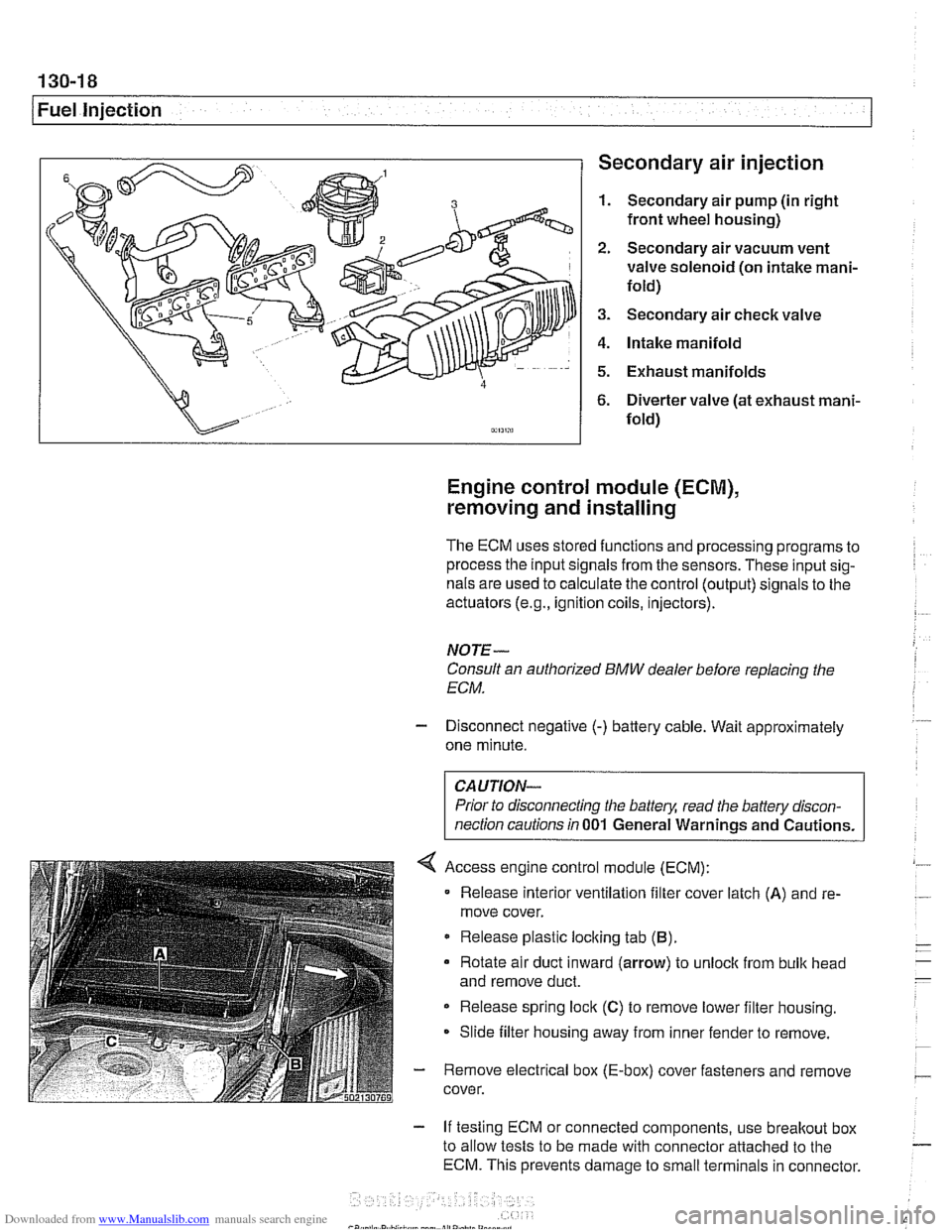
1 Fuel injection Secondary air injection
1. Secondary air pump (in right
front wheel housing)
2. Secondary air vacuum vent
valve solenoid (on intake mani-
fold)
3. Secondary air check valve
4. Intake manifold
5. Exhaust manifolds
6. Diverter valve (at exhaust mani-
fold)
Engine control module (ECM),
removing and installing
The ECM uses stored functions and processing programs to
process the input signals from the sensors. These input sig-
nals are used to calculate the control (output) signals to the
actuators
(e.g., ignition coils, injectors).
NOTE-
Consult an authorized BMW dealer before replacing the
ECM.
- Disconnect negative (-) battery cable. Wait approximately
one minute.
Prior to disconnecting the
battely, read the battery discon-
nection cautions in
001 General Warnings and Cautions.
Access engine control module (ECM):
Release interior ventilation filter cover latch
(A) and re-
move cover.
Release plastic locking tab
(B).
Rotate air duct inward (arrow) to unloclc from bulk head
and remove duct.
Release spring lock
(C) to remove lower filter housing.
Slide filter housing away from inner fender to remove.
- Remove electrical box (E-box) cover fasteners and remove
cover.
- If testing ECM or connected components, use breakout box
to allow tests to be made with connector attached to the
ECM. This prevents damage to small terminals in connector.
Page 409 of 1002
Downloaded from www.Manualslib.com manuals search engine
Fuel Injection I
- As an alternative, harness connector housing can be sepa-
rated so that electrical
checlts can be made from backof con-
nector.
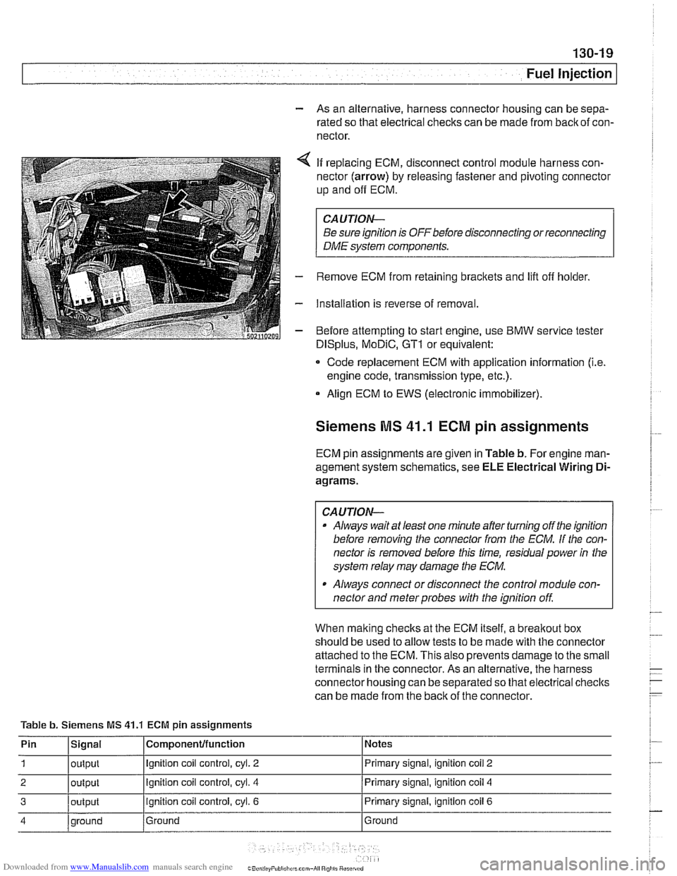
4 If replacing ECM, disconnect control module harness con-
nector (arrow) by releasing fastener and pivoting connector
up and
off ECM.
CAUTION-
Be sure ignition is OFF before disconnecting or reconnecting
DME system components.
- Remove ECM from retaining brackets and lift off holder.
- Installation is reverse of removal.
- Before attempting to start engine, use BMW service tester
DISplus, MoDiC, GTI or equivalent:
- Code replacement ECM with application information (i.e.
engine code, transmission type, etc.).
Align ECM to EWS (electronic immobilizer).
Siemens MS 41.1 ECM pin assignments
ECM pin assignments are given in Table b. For engine man-
agement system schematics, see ELE Electrical Wiring
Di-
agrams.
CAUTION-
a Always wait at least one minute after turning off the ignition
before removing the connector from the
ECM. If the con-
nector is removed before this time, residual power
in the
system relay may damage the
ECM.
Always connect or disconnect the control module con-
nector and meter probes with the ignition
off
When malting checks at the ECM itself, a breakout box
should be used to allow tests to be made with the connector
attached to the ECM. This also prevents damage to the small
terminals in the connector. As an alternative, the harness
connector housing can be separated so that electrical checlts
can be made from the back of the connector.
Table b. Siemens MS
41.1 ECM pin assignments
Pin
1
2
3
4
Signal
output
output
output
qround Componenfffunction
Ignition coil control, cyl. 2
Ignition coil control, cyl. 4
ignition coil control, cyl. 6
Ground Notes
Primary signal,
ignition
coil 2
Primary signal, ignition coil 4
Primary signal, ignition coil 6
Ground
Page 419 of 1002
Downloaded from www.Manualslib.com manuals search engine
Fuel Injection
A faulty MAF sensor can produce the following problems:
Difficult to restart when engine is hot
Engine starts then stalls
* Engine starts and runs only with accelerator pedal de-
pressed
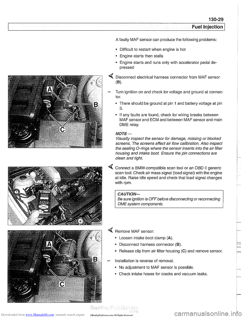
4 Disconnect electrical harness connector from MAF sensor
(B).
- Turn ignition on and checlc for voltage and ground at connec-
tor.
There should be ground at pin
1 and battery voltage at pin
3.
- If any faults are found, checlc for wiring breaks between
MAF sensor and ECM and between MAF sensor and main
DME relay.
NOTE-
Visually inspect the sensor for damage, missing or blocked
screens. The screens affect air flow calibration. Also inspect
the sealina
0-rinas where the sensor inserts into the air filter - - housing and intake boot. Ensure the pin connections are
clean and tight.
4 Connect a BMW-compatible scan tool or an OED II generic
scan tool.
Checlc air mass signal (load signal) with the engine
at idle. Raise idle speed and
checlc that load signal changes
with rpm.
CAUTION-
Be sure ignition is OFFbefore disconnecting or reconnecting
DME system components.
Remove MAF sensor:
Loosen intake boot clamp
(A).
Disconnect harness connector (6).
* Release clip from air filter housing (C) and remove sensor.
- Installation is reverse of removal.
No adjustment to MAF sensor is possible.
Check intake hoses for cracks and vacuum
lealts.
Page 430 of 1002
Downloaded from www.Manualslib.com manuals search engine
130-40
Fuel Injection
Engine control module (ECM),
removing and installing
The ECM uses stored functions and processing programs to
process the input signals from the sensors. These input sig-
nals are used to calculate the control (output) signals to the
actuators
(e.g., ignition coils, injectors).
NOTE-
Consult an authorized BMW dealer before replacing the
ECM.
- Disconnect negative (-) battery cable. Wait approximately
one minute.
CAUTION-
Prior to disconnecting the batteg read the battery discon-
nection cautions
in 001 General Warnings and Cautions.
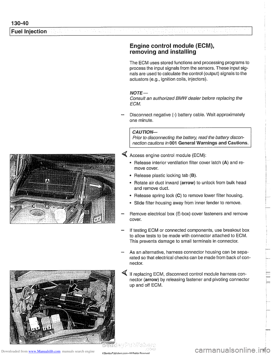
4 Access engine control module (ECM):
Release
interlor ventilation filter cover latch (A) and re-
move cover.
Release plastic loclting tab
(B).
Rotate air duct inward (arrow) to unloclt from bulk head
and remove duct.
Release spring lock
(C) to remove lower filter housing.
Slide
f~lter hous~ng away from inner fender to remove.
- Remove electrical box (E-box) cover fasteners and remove
cover.
- If testing ECM or connected components, use breakout box
to allow tests to be made with connector attached to ECM.
This prevents damage to small terminals in connector.
- - As an alternative, harness connector housing can be sepa-
rated so that electrical checks can be made from
back of con-
nector.
4 If replacing ECM, disconnect control module harness con-
nector (arrow) by releasing fastener and pivoting connector
up and off ECM.
Page 431 of 1002
Downloaded from www.Manualslib.com manuals search engine
. -
Fuel Injection I
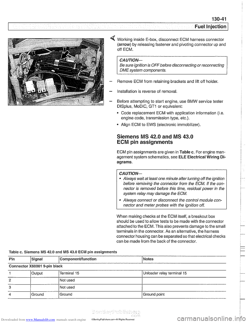
Working inside E-box, disconnect ECM harness connector
(arrow) by releasing fastener and pivoting connector up and
off ECM.
CA UTIOW
Be sure ignition is OFF before disconnecting or reconnecting
DME system components.
Remove ECM from retaining brackets and lift off holder.
Installation is reverse of removal
Before attempting to start engine, use
BMW service tester
DISplus, MoDiC, GTl or equivalent:
* Code replacement ECM with application information (i.e
engine code, transmission type, etc.).
Align ECM to EWS (electronic immobilizer).
Siemens MS 42.0 and MS 43.0
ECM pin assignments
ECM pin assignments are given in Table c. For engine man-
agement system schematics, see
ELE Electrical Wiring Di-
agrams.
/ CAUTIOW I
Al~ays wait at least one mfnule after turning off the ignition
before
remov;ng [he connecror irom rhe ECM. If the con-
nector is removed before this time, residual power
in the
system relay may damage the
ECM.
Always connect or disconnect the control module con-
nector and meter probes with the ignition off.
When making checks at the ECM itself, a
breakout box
should be used to allow tests to be made with the connector
attached to the ECM. This also prevents damage to the small
terminals in the connector. As an alternative, the harness
connector housing can be separated so that electrical checks
can be made from the back of the connector.
Table
c. Siemens MS 42.0 and MS 43.0 ECM pin assignments
Pin
lslgnal l~om~onentlfunction 1 Notes
Connector
X60001 9-pin black
1 loutput I~erminai 15 I Unloeder relay terminal 15
2 I 1 Not used I
3 Not used
4 Ground
Ground Ground
point
Page 457 of 1002
Downloaded from www.Manualslib.com manuals search engine
130-67
Fuel Injection /
ME 7.2 system overview
The Bosch ME 7.2 system is used on 1999 - 2002 540i mod-
els.
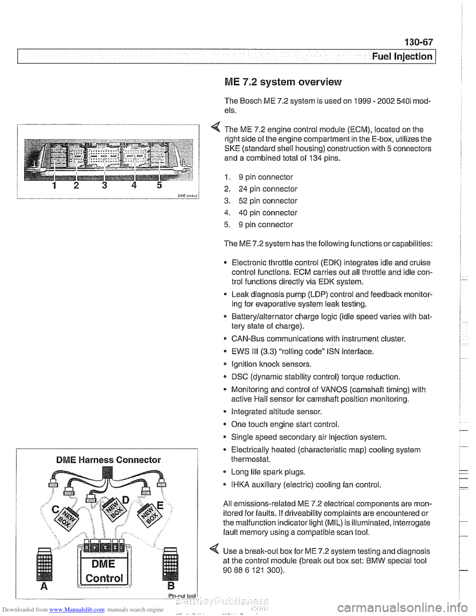
1 4 The ME 7.2 enaine control module (ECM). located on the
l and a combined total of 134 pins.
--__-- 1 I. 9 pin connector
12 3 4 5 2 24 pin connector
0lliC;nii, 3. 52 pin connector
4. 40 pin connector
5. 9 pin connector
The ME 7.2 system has the following functions or capabilities:
Electronic throttle control (EDK) integrates idle and cruise
control functions. ECM carries out all throttle and idle con-
trol functions directly via EDK system.
Leak diagnosis pump
(LDP) control and feedback monitor-
ing for evaporative system leak testing.
Batterylalternator charge logic (idle speed varies with bat-
tery state of charge).
CAN-Bus communications with instrument cluster.
EWS
111 (3.3) "rolling code" ISN interface.
Ignition
knock sensors.
DSC (dynamic stability control) torque reduction.
Monitoring and control of VANOS
(camshaft timing) with
active Hail sensor for camshaft position monitoring.
Integrated altitude sensor.
One touch engine start control
Single speed secondary air injection system.
Long life spark plugs.
IHKA auxiliary (electric) cooling fan control.
All emissions-related ME 7.2 electrical components are mon-
itored for faults. if driveability complaints are encountered or
the malfunction indicator
light (MIL) is illuminated, interrogate
fault memory using a compatible scan tool.
4 Use a break-out box for ME 7.2 system testing and diagnosis
at the control module
(break out box set: BMW special tool
90
88 6 121 300).
Electrically heated (characteristic
map) cooling system
DME Harness Connector thermostat.
Page 543 of 1002
Downloaded from www.Manualslib.com manuals search engine
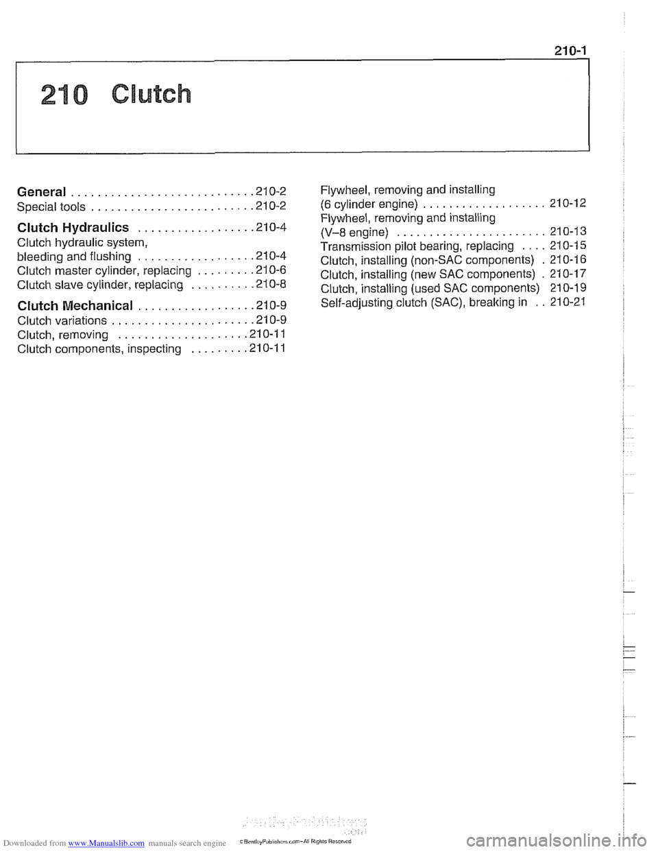
210 Clutch
........................... General .21 0.2
........................ Special tools .21 0.2
Clutch Hydraulics ................. .21 0.4
Clutch hydraulic system.
bleeding and flushing
................. .21 0.4
Clutch master cylinder. replacing
........ .21 0.6
Clutch slave cylinder. replacing ......... .21 0.8 Flywheel. removing
and installing
................... (6 cylinder engine) 210-12
Flywheel. removing and installing
(V-8 engine) ....................... 21 0-1 3
Transmission pilot bearing. replacing .... 210-1 5
Clutch. installing (non-SAC components) . 210-1 6
Clutch. installing (new SAC components)
. 21 0-17
Clutch.
install in^ (used SAC components) 210-19
Clutch Mechanical ................. .21 0.9 self-adjusting crutch (SAC). breaking in : . 210-21
..................... Clutch variations .21 0.9
................... Clutch. removing .21 0.1 1
Clutch components. inspecting
........ .21 0.1 1
Page 563 of 1002
Downloaded from www.Manualslib.com manuals search engine
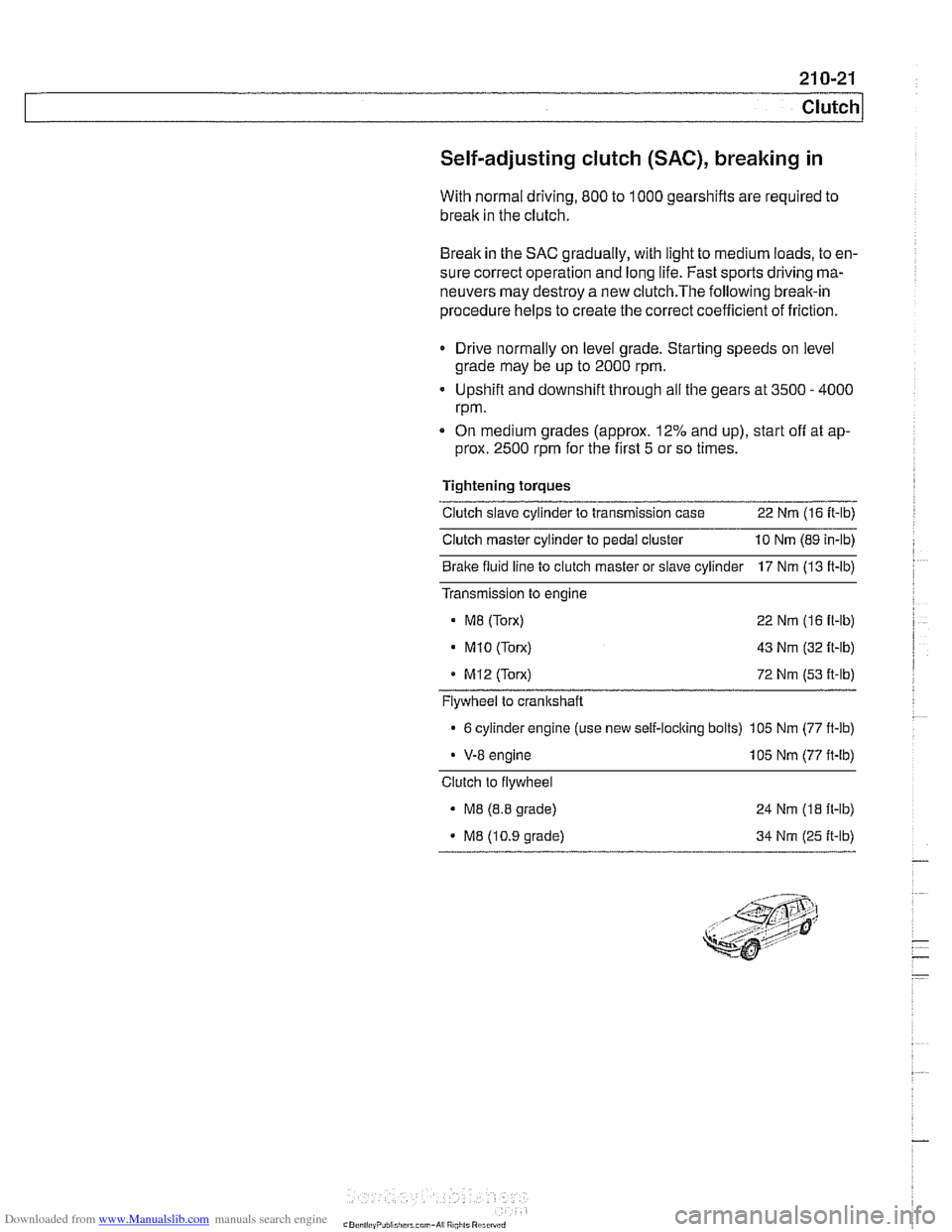
Self-adjusting clutch (SAC), breaking in
With normal driving, 800 to 1000 gearshifts are required to
break in the clutch.
Break in the SAC gradually, with light to medium loads, to en-
sure correct operation and long life. Fast sports driving ma-
neuvers may destroy a new
clutch.The following break-in
procedure helps to create the correct coefficient of friction.
Drive normally on level grade. Starting speeds on level
grade may be up to 2000 rpm.
Upshift and downshift through all the gears at 3500
- 4000
rpm.
On medium grades (approx. 12% and up), start
off at ap-
prox. 2500 rpm for the first 5 or so times.
Tightening torques
Clutch slave cylinder to transmission case 22 Nm (16 It-lb)
Clutch master cylinder to pedal cluster 10 Nm (89 in-lb)
Bralte fluid line to clutch master or slave cylinder 17 Nm (13 ft-lb)
Transmission to engine
M8 (Torx) 22 Nm (16 fl-lb)
. M1O (Torx) 43 Nm (32 ft-lb)
MI2 (Torx) 72 Nm (53 it-lb)
Flywheel to crankshaft
6 cylinder engine (use new self-loclting bolts) 105 Nm (77 ft-lb)
V-8 engine 105 Nm (77 ft-lb)
Clutch to flywheel
M8 (8.8 grade)
M8 (10.9 grade) 24
Nm
(18 ft-lb)
34 Nm (25 ft-lb)
Page 728 of 1002
Downloaded from www.Manualslib.com manuals search engine
I Rear Suspension
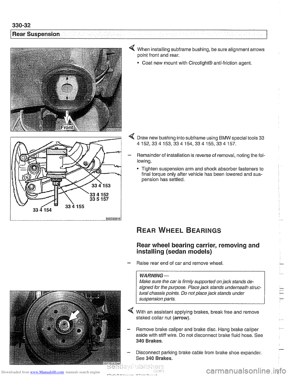
4 When installing subframe bushing, be sure alignment arrows
point front and rear.
Coat new mount with
CircolightB anti-friction agent.
< Draw new bushing into subframe using BMW special tools 33
4152,334153,334154,334155,334157.
- Remainder of installation is reverse of removal, noting the fol-
lowing.
* Tighten suspension arm and shock absorber fasteners to
final torque only after vehicle has been lowered and
sus-
oension has settled.
Rear wheel bearing carrier, removing and
installing (sedan models)
- Raise rear end of car and remove wheel
WARNING-
Make sure the car is firmly supported on jaclc stands de-
signed for the purpose. Place
jaclc stands underneath struc-
tural chassis points. Do not place jaclc stands under
suspension parts.
4 With an assistant applying brakes, break free and remove
staked collar nut (arrow).
- Remove brake caliper and brake disc. Hang brake caliper
aside with stiff wire. Do not disconnect brake fluid hose. See
340 Brakes.
- Disconnect parking brake cable from brake shoe expander.
See 340 Brakes.