break BMW 525i 2001 E39 Owner's Manual
[x] Cancel search | Manufacturer: BMW, Model Year: 2001, Model line: 525i, Model: BMW 525i 2001 E39Pages: 1002
Page 733 of 1002
Downloaded from www.Manualslib.com manuals search engine
Rear suspension/
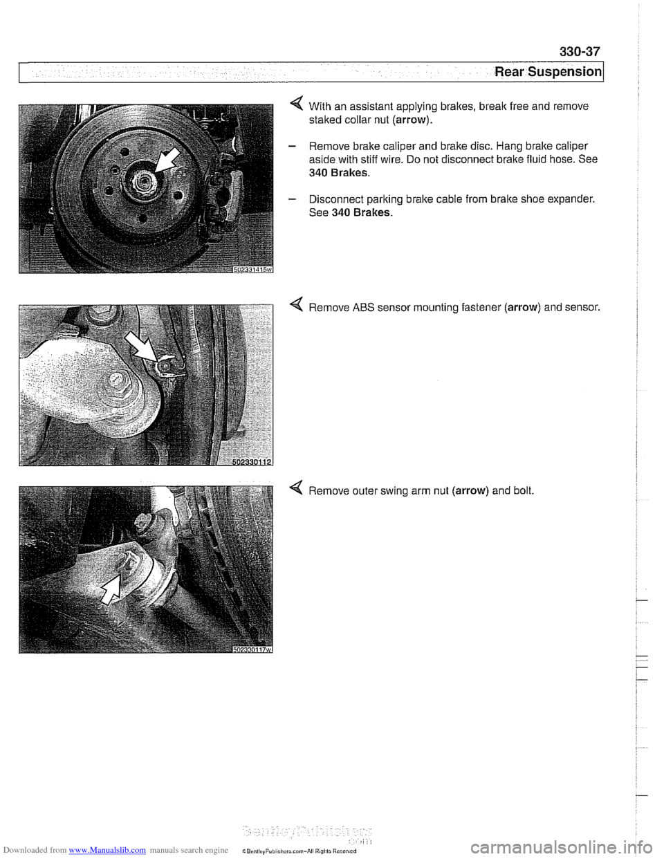
4 With an assistant applying brakes, break free and remove
staked collar nut (arrow).
- Remove brake caliper and brake disc. Hang bralte caliper
aside with stiff wire. Do not disconnect brake fluid hose. See
340 Brakes.
- Disconnect parking brake cable from brake shoe expander.
See 340 Brakes.
Remove ABS sensor mounting fastener
(arrow) and sensor.
Remove outer swing arm nut (arrow) and bolt.
Page 736 of 1002
Downloaded from www.Manualslib.com manuals search engine
330-40
Rear Suspension
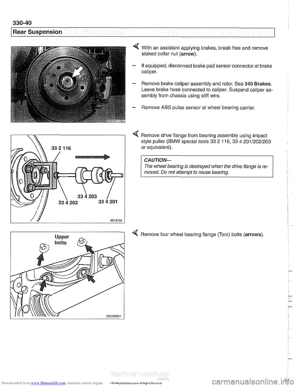
4 With an assistant applying brakes, break free and remove
staked collar nut (arrow).
- If equipped, disconnect brake pad sensor connector at brake
caliper.
- Remove brake caliper assembly and rotor. See 340 Brakes.
Leave brake hose connected to caliper. Suspend caliper as-
sembly from chassis using stiff wire.
- Remove ABS pulse sensor at wheel bearing carrier.
Remove drive flange from bearing assembly using impact
style puller
(BMW special tools 33 2 116, 33 4 201/202/203
or equivalent).
CAUTION-
The wheel bearing is destroyed when the drive flange is re-
moved. Do not attempt to reuse bearing.
4 Remove four wheel bearing flange (Torx) bolts (arrows)
Page 758 of 1002
Downloaded from www.Manualslib.com manuals search engine
Final Drive
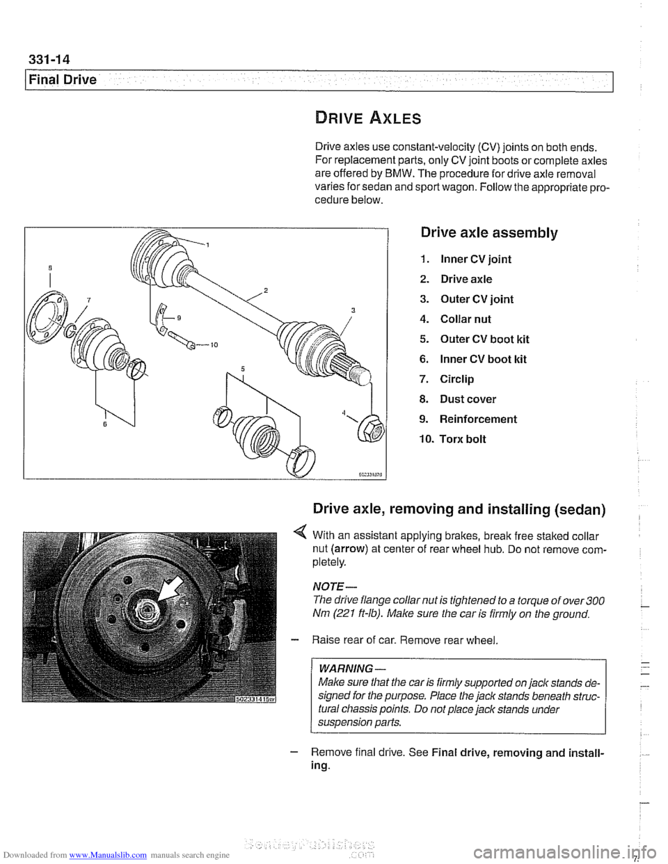
Drive axles use constant-velocity (CV) joints on both ends.
For replacement parts, only CV joint boots or complete axles
are offered by BMW. The procedure for drive axle removal
varies for sedan and sport wagon. Follow the appropriate pro-
cedure below.
Drive axle assembly
1. lnner CV joint
2. Drive axle
3. Outer CV joint
4. Collar nut
5. Outer CV boot kit
6. lnner CV boot kit
7. Circlip
8. Dust cover
9. Reinforcement
10. Torx bolt
Drive axle, removing and installing (sedan)
4 With an assistant applying brakes, break free staked collar
nut (arrow) at center of rear wheel hub. Do not remove com-
pletely.
NOTE-
The drive flange collar nut is tightened to a torque of over 300
Nm (221 ft-lb). Male sure the car is firmly on the ground.
- Raise rear of car. Remove rear wheel
WARNING -
Make sure that the car is firmly supported on jack stands de-
signed for the purpose. Place the
jack stands beneath struc-
tural chassis points. Do not place jack stands under
suspension parts.
- Remove f~nal drrve. See Final drive, removing and install-
ing.
Page 765 of 1002
Downloaded from www.Manualslib.com manuals search engine
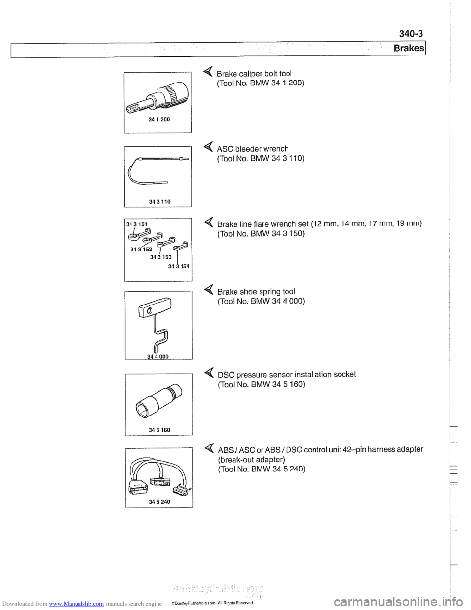
, Brake caliper bolt tool
4 ASC bleeder wrench
(Tool No. BMW 34
3 110)
4 Brake line flare wrench set (12 mm, 14 mm, 17 mm, 19 rnm)
(Tool No. BMW 34 3 150)
34 3 152
34 3 153
34 3 154
4 DSC Dressure sensor installation socltet
4 ABS IASC or ABSI DSC control unit 42-pin harness adapter
(break-out adapter)
(Tool No. BMW 34 5 240)
0
(Tool NO. BMW 34 5 160)
Page 852 of 1002
Downloaded from www.Manualslib.com manuals search engine
-
Exterior Trim, Bumpers
This repair group includes repair information for the outside
rearview mirrors, front and rear bumpers, and the easily re-
movable exterior trim parts.
Many of the mirror components are separately available from
an authorized
BMW dealer, including the glass and outside .
plastic housing.
The
E39 models offered two types of outside mirrors, stan-
dard mirrors or automatic dip mirrors.
Outside mirror glass, replacing
CAUTIOI\C
Mirrorshould be at or above room temperature before remov-
al.
Othe~lise, small plastic parfs or glass may break.
Outside mirror glass without automatic dip control,
replacing
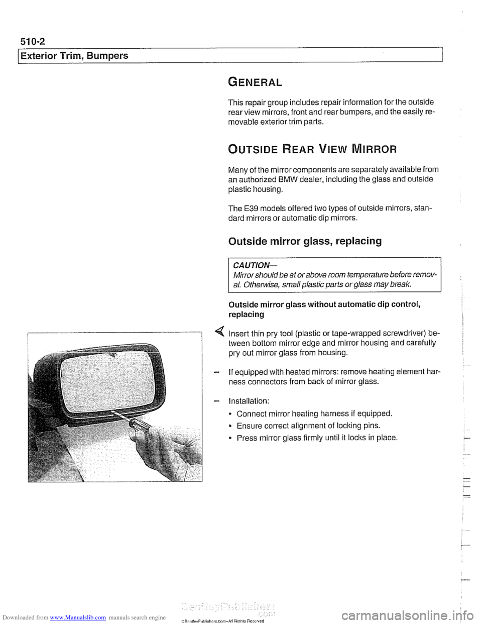
Insert thin pry tool (plastic or tape-wrapped screwdriver) be-
tween bottom mirror edge and mirror housing and carefully
pry out mirror glass from housing.
If equipped with heated mirrors: remove heating element
har.
ness connectors from back of mirror glass.
Installation: Connect mirror heating harness if equipped.
Ensure correct alignment of locking pins.
Press mirror glass firmly until it
locks in place.
Page 895 of 1002
Downloaded from www.Manualslib.com manuals search engine
51 5 Central Locking and Anti-Theft
........................... General .51 5.2
Central Locking ................... .51 5.2
General Module
..................... .51 5.2
Central locking inputs and outputs
....... .51 5.3
Doorlocks
........................... 515-5
Trunklock
........................... 515-7
Remote entry (FZV)
.................. .51 5.7
Remote entry (FZV) inputs and outputs ... .51 5.8
Car Memory I Key Memory ............ .51 5.12
Trunk lid soft close (SCA)
............. .51 5.13
SCA subsystem
.................... .51 5.14
........ Tailgate and rear window locks
.51 5.14
Sport Wagon tailgate and rear
window
lock schematic ............... .51 5.15
Door Handles and Locks .......... .51 5.16
Door handle (outer), removing
and installing
....................... .51 5.16
Door latch, removing and installing
..... .51 5.17
Outer door lock cylinder, removing
and installing
....................... .51 5.18
Trunk Lock Assembly ............. 515-1 9
Trunk lock. removing and installing
...... 515-19
Trunk lock striker plate. removing
and installing
....................... 515-20
Tailgate lock. emergency release
....... 515-21
... Electronic Immobilization (EWS) 515-21
EWS variations
..................... 515-22
......... EWS control module. replacing 515-23
Transmitter
1 receiver module .......... 515-23
....................... Ring antenna 515-23
Anti-theft System (DWA) ........... 51 5-24
DWA LED Status
.................... 51 5-24
Tilt sensor
......................... 515-24
Interior protection .................... 51 5-25
Glass breakage sensors
.............. 515-26
Emergency disarming
................ 51 5-26
Page 920 of 1002
Downloaded from www.Manualslib.com manuals search engine
51 5-26
Central Locking and Anti-Theft
Interior sensor UIS (2000 and later models)
The
UIS system uses ultrasonic sound waves instead of elec-
tromagnetic waves. Ultrasonic sound waves are less suscep-
tible to magnetic interference.
Every time the DWA system is armed, the sensor adapts to
whatever objects might be stationary in the interior. The sen-
sor emits ultrasonic waves in a programmed timed cycle. It re-
ceives echoes of the emitted waves. The
UIS amplifies the
received sound wave signals and compares them to the ech-
oes of the transmitted waves. The
UIS also checits the incom-
ing echoes for background hiss (wind noise through a
partially open window) and adapts for this.
If the echoes are consistently similar, no movement is de-
tected.
If the echoes are altered, (inconsistent), the UIS deter-
mines motion in the interior compartment.
If motion is detected, the
UIS changes to a constant cycle
and the echo is compared again.
If the inconsistency is still present the
UIS sends the acti-
vate siren signal to the GM.
Glass breakage sensors
The doorwindows are monitored by inductive sensors mount-
ed on the inside of the door behind the trim panel. A closed
window is recognized by a magnetic plate
on the glass lining
up with the sensor. If the glass is broken, the plate falls away
and the signal from the sensor changes. This causes the GM
to activate the alarm.
Emergency disarming
- An emergency procedure is provided to cancel the DWA in
the event that a fault occurs within the system. The procedure
is as follows:
Driver's door mechanically
unloclted and open within 30
seconds. This will cause triggering of alarm.
All doors closed.
Ignition switch turned to
KL R (ACCESSORY). LED indica-
tor will come on.
- After 10 minutes, alarm is disarmed
Page 959 of 1002
Downloaded from www.Manualslib.com manuals search engine
721 -1 1
Airbag System (SRS)~
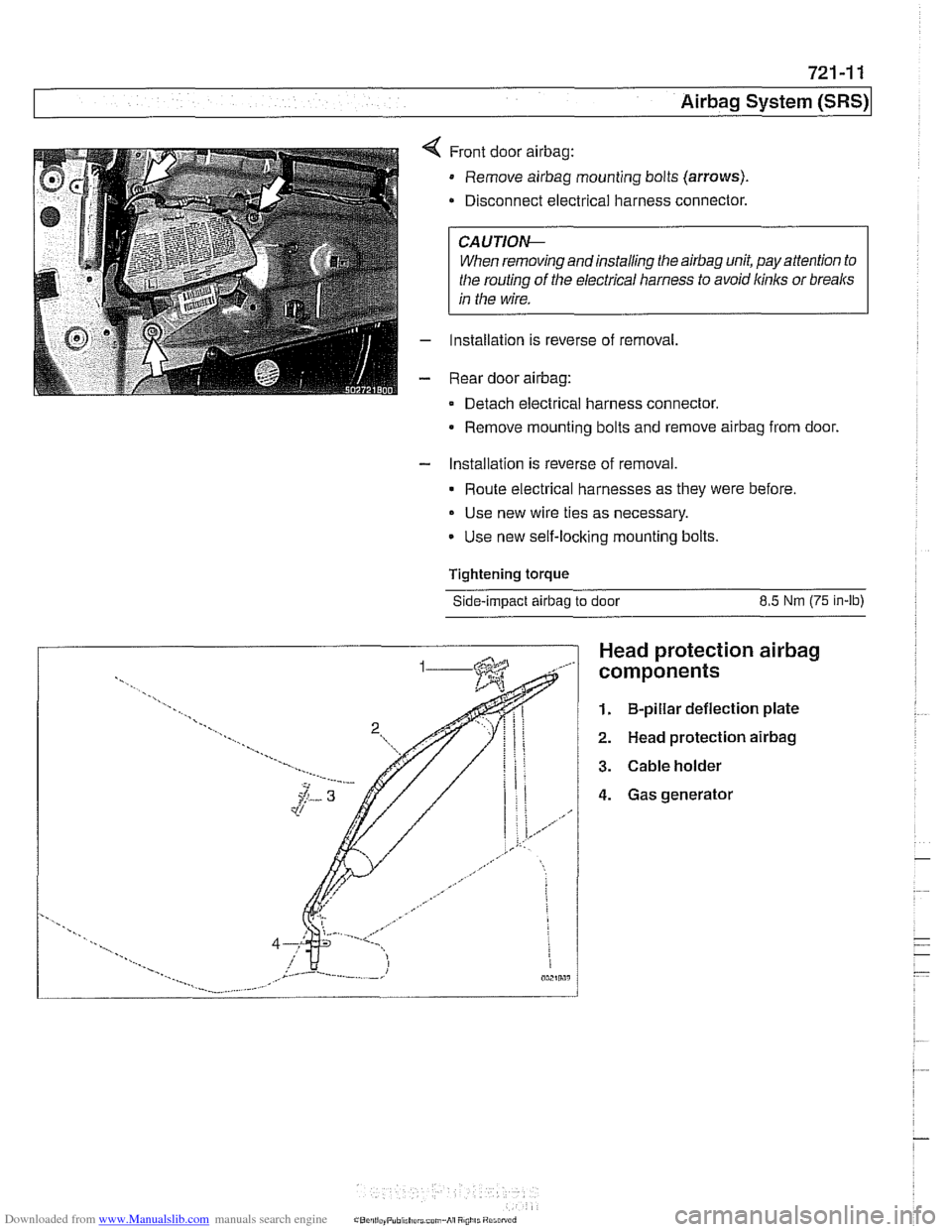
Front door airbag:
Remove airbag mounting bolts (arrows).
Disconnect electrical harness connector.
CAUTIOI\C
When removing andinstalling the airbag unit, pay attention to
the routing
of the electrical harness to avoid kinks or breaks
in the wire.
Installation is reverse of removal,
Rear door
airbag:
Detach electrical harness connector.
Remove mounting bolts and remove
airbag from door.
- Installation is reverse of removal.
Route electrical harnesses as they were before.
Use new wire ties as necessary.
Use new self-locking mounting bolts.
Tightening
torque
Side-impact airbag to door 8.5 Nm (75 in-lb)
Head protection airbag
components
1. B-pillar deflection plate
2. Head protection airbag
3. Cable holder
4. Gas generator