thermostat BMW 525i 2001 E39 Owner's Guide
[x] Cancel search | Manufacturer: BMW, Model Year: 2001, Model line: 525i, Model: BMW 525i 2001 E39Pages: 1002
Page 518 of 1002
Downloaded from www.Manualslib.com manuals search engine
.. - --
Radiator and Cooling System
Tightening torques
Coolant pump to timing chain 10
Nm (89 in-lb)
cover
Coolant pump
pulley to coolant
pump
10 Nm (89 in-lb
Engine
blocic drain plug to block 25 Nm (18 ft-lb)
Radiator drain plug to radiator
2-3Nm(18-27in-lb)
Thermostat cover to coolant
pump assembly 10 Nm (89 in-lb)
Radiator, removing and installing
Removal of the radiator is similar for V-8 and 6-cylinder mod-
els.
- Raise front of car and support safely.
WARNING -
Make sure the car is stable and well supported at aN times.
Use a professional automotive liff
orjaclc stands designed for
- Remove splash shield from under engine.
- Drain radiator and engine block. See Coolant, draining and
filling
(V-8 models).
WARNING -
Allow cooling system to cool before opening or draining sys-
tem.
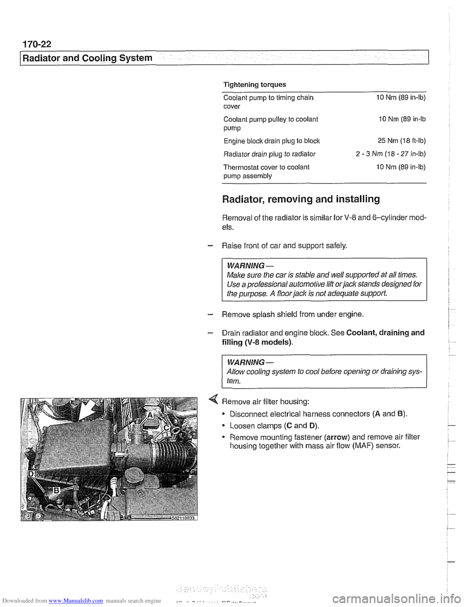
< Remove air filter housing:
Disconnect electrical harness connectors
(A and B).
Loosen clamps (C and D).
Remove mounting fastener (arrow) and remove air filter
housing together with mass air flow
(MAF) sensor.
Page 976 of 1002
Downloaded from www.Manualslib.com manuals search engine
--- -
On-Board Diagnostics - - --- - -- - -
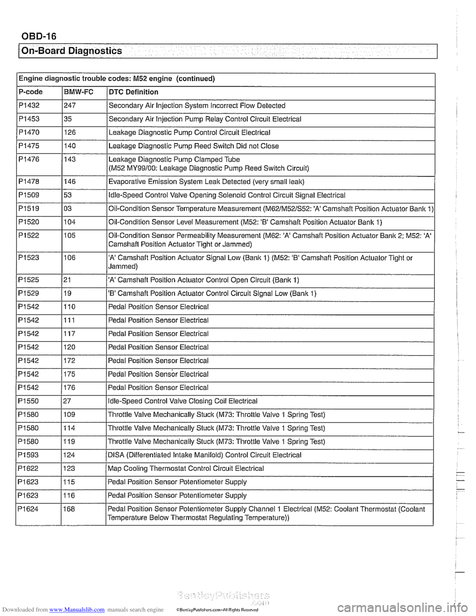
PI542
PI550
PI580
PI 580
PI 580
PI 593
PI622
PI623
PI623
PI 624 176
27 109
114
119
124
123
115
116
168 Pedal Position Sensor Electrical
Idle-Speed
Control Valve Closing Coil Electrical
Throttle Valve Mechanically Stuck
(M73: Throttle Valve 1 Spring Test)
Throttle Valve Mechanically Stuck
(M73: Throttle Valve 1 Spring Test)
Throttle Valve Mechanically Stuck
(M73: Throttle Valve 1 Spring Test)
DlSA (Differentiated lntalte Manifold) Control Circuit Electrical
Map Cooling Thermostat Control Circuit Electrical
Pedal Position Sensor Potentiometer Supply
Pedal Position Sensor Potentiometer Supply
Pedal Position Sensor Potentiometer Supply Channel
1 Electrical (M52: Coolant Thermostat (Coolant
Temperature Below Thermostat Regulating Temperature))
Page 977 of 1002
Downloaded from www.Manualslib.com manuals search engine
On-Board ~iaanosticsl
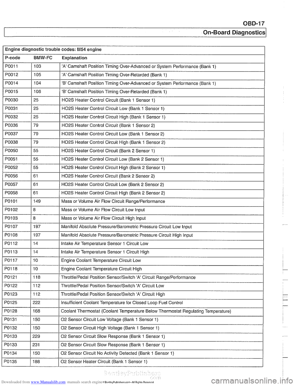
Engine diagnostic trouble codes: M54 engine
P-code
BMW-FC Explanation
PO01 I / 103 I 'A' Camshaft Position Timing Over-Advanced or System Performance (Banlc 1) I I
PO012 1105 I 'A' Camshaft Position Timing Over-Retarded (Bank 1) I I
PO01 4 1104 I 'B' Camshaft Position Timing Over-Advanced or System Performance (Bank 1)
PO01 5
PO030
PO031
PO032
I 1
PO038 179 / HO2S Heater Control Circuit High (Bank 1 Sensor 2)
I I -.
I I
PO050 1 55 I H02S Heater Control Circuit (Bank 2 Sensor 1)
106
25
25
25
PO036
I I
PO051 1 55 I H02S Heater Control Circuit Low (Bank 2 Sensor 1)
'B' Camshaft Position Timing Over-Retarded (Bank 1)
H02S Heater Control Circuit (Bank 1 Sensor 1)
H02S Heater Control Circuit Low (Bank 1 Sensor 1)
H02S Heater Control Circuit Hiqh (Bank 1 Sensor 1)
PO037 1 79 I HO2S Heater Control Circuit Low (Bank 1 Sensor 2)
79
HOPS Heater
Control Circuit (Banlc 1 Sensor 2)
PO052
PO056
PO057
PO058
I I
PO1 03 / 8 I Mass or Volume Air Flow Circuit High. Input
I I -.
I I
PO1 07 1 197 I Manifold Absolute PressureIBarometric Pressure Circuit Low Input
55
61
61
61
PO101
I I
POI08 1197 / Manifold Absolute PressureIBarometric Pressure Circuit High Input
H02S Heater Control Circuit High (Bank 2 Sensor 1)
H02S Heater Control Circuit (Bank 2 Sensor 2)
HO2S Heater Control Circuit Low (Bank 2 Sensor 2)
HO2S Heater Control Circuit Hiqh (Banlc 2 Sensor 2)
PO102 18 I Mass or Volume Air Flow Circuit Low Input
149
I I -
PO122 112 ThrottleIPedai Position SensorISwitch 'A' Circuit Low
PO123 1112 I ThrottleIPedal Position SensorISwitch 'A' Circuit High
Mass
or Volume Air Flow Circuit
RangeIPerformance
PO112
PO113
PO1 17
PO118
PO121
14
14
10
10
118
PO128
PO1 31
PO132
PO133
PO133
PO1 34 Intake
Air Temperature Sensor 1 Circuit Low
Intake Air Temperature Sensor 1 Circuit High
Engine Coolant Temperature Circuit Low
Engine Coolant Temperature Circuit High
ThrottleIPedal Position SensorISwitch 'A' Circuit RanqeIPerformance
I I
168
150
150
229
231
150
PO135
Coolant Thermostat (Coolant Temperature Below Thermostat Regulating Temperature)
02 Sensor Circuit Low Voltage (Bank 1 Sensor 1)
02 Sensor Circuit High Voltage (Bank 1 Sensor 1)
02 Sensor Circuit Slow Response (Bank
1 Sensor 1)
02 Sensor Circuit Slow Response
(Banlc 1 Sensor 1)
02 Sensor Circuit No Activitv Detected
(Banlc 1 Sensor 1)
188 02 Sensor Heater Circuit (Bank 1 Sensor 1)
Page 983 of 1002
![BMW 525i 2001 E39 Owners Guide Downloaded from www.Manualslib.com manuals search engine
OBD-23
On-Board ~iagnostics]
I I
PI625 / 147 I Pedal Position Sensor Potentiometer Supply Channel 2 Electrical 1
Engine diagnostic troubl BMW 525i 2001 E39 Owners Guide Downloaded from www.Manualslib.com manuals search engine
OBD-23
On-Board ~iagnostics]
I I
PI625 / 147 I Pedal Position Sensor Potentiometer Supply Channel 2 Electrical 1
Engine diagnostic troubl](/img/1/2822/w960_2822-982.png)
Downloaded from www.Manualslib.com manuals search engine
OBD-23
On-Board ~iagnostics]
I I
PI625 / 147 I Pedal Position Sensor Potentiometer Supply Channel 2 Electrical 1
Engine diagnostic trouble codes: M54 engine (continued)
P-code
BMW-FC Explanation
PI 604
PI604
PI619
PI620
PI624
PI632
PI633
PI634
P1 634
PI 634
PI 635
PI 636 50
51 123
123
146 i I
I
I Barometric Pressure Circuit Low
Control
Module Self-Test,
Speed Monitoring
Control Module Self-Test, Speed Monitoring
Map Cooling Thermostat Control Circuit Signal Low
Map Cooling Thermostat Control Circuit Signal High Pedal Position Sensor Potentiometer Supply Channel
1 Electrical (M52: Coolant Thermostat (Coolant
Temperature Below Thermostat Regulating Temperature))
115
115
115
135
136
115
109
PI639
PI675
PI694
P2088
P2089
P2090
P2091
I I
P2229 1197 I Barometric Pressure Circuit High
Throttle
Valve Adaptation Conditions Not Met
Throttle
Valve Adaptation Limp-Home Position Unknown
Throttle Valve Adaptation Spring Test Failed
Throttle
Valve Adaptation Spring Test Failed
Throttle
Valve Adaptation Spring Test Failed
Throttle Valve Adaptation Lower Mechanical Stop not Adapted
Throttle Valve Control Circuit
Throttle Valve Position Control, Control Deviation
PI 637
I I
P2270 1215 1 02 Sensor Signal Stuck Lean (Banic 1 Sensor 2)
PI 638 1160 I Throttle Valve Position Control Throttle Stucic Temporarily
162
161
135
136
21
21 19
19 Throttle
Valve Position Control Throttle
Stucic Permanently
Throttle Valve Actuator Start Test Re-Adaptation Required
Throttle Valve Actuator Start Test Spring Test and Limp-Home Position Failed
'A' Camshaft Position Actuator Control Circuit Low (Banlc 1)
'A' Camshaft Position Actuator Control Circuit High (Banlc 1)
'B' Camshaft Position Actuator Control Circuit Low (Bank 1)
'B' Camshaft Position Actuator Control Circuit High (Bank 1)
P2271
P2272
P2273
P3041
P3198 I I -
215
216
21 6
10481
10205 02
Sensor Signal Stucic Lean (Bank 1 Sensor 2)
02 Sensor Signal
Stuclc Lean (Bank 2 Sensor 2)
02 Sensor Signal Stuclc Lean (Bank 2 Sensor 2)
02 Sensor Lean and Rich Voltage Thresholds not Reached (Bank 2 Sensor 2)
Engine Coolant Temperature Gradient Too High
Engine Coolant Temperature Signal Stuck
P3199
P3238 1 10289 I Control Module Monitoring TPU Chip Defective
10207
Page 984 of 1002
Downloaded from www.Manualslib.com manuals search engine
/ On-Board Diaanostics I
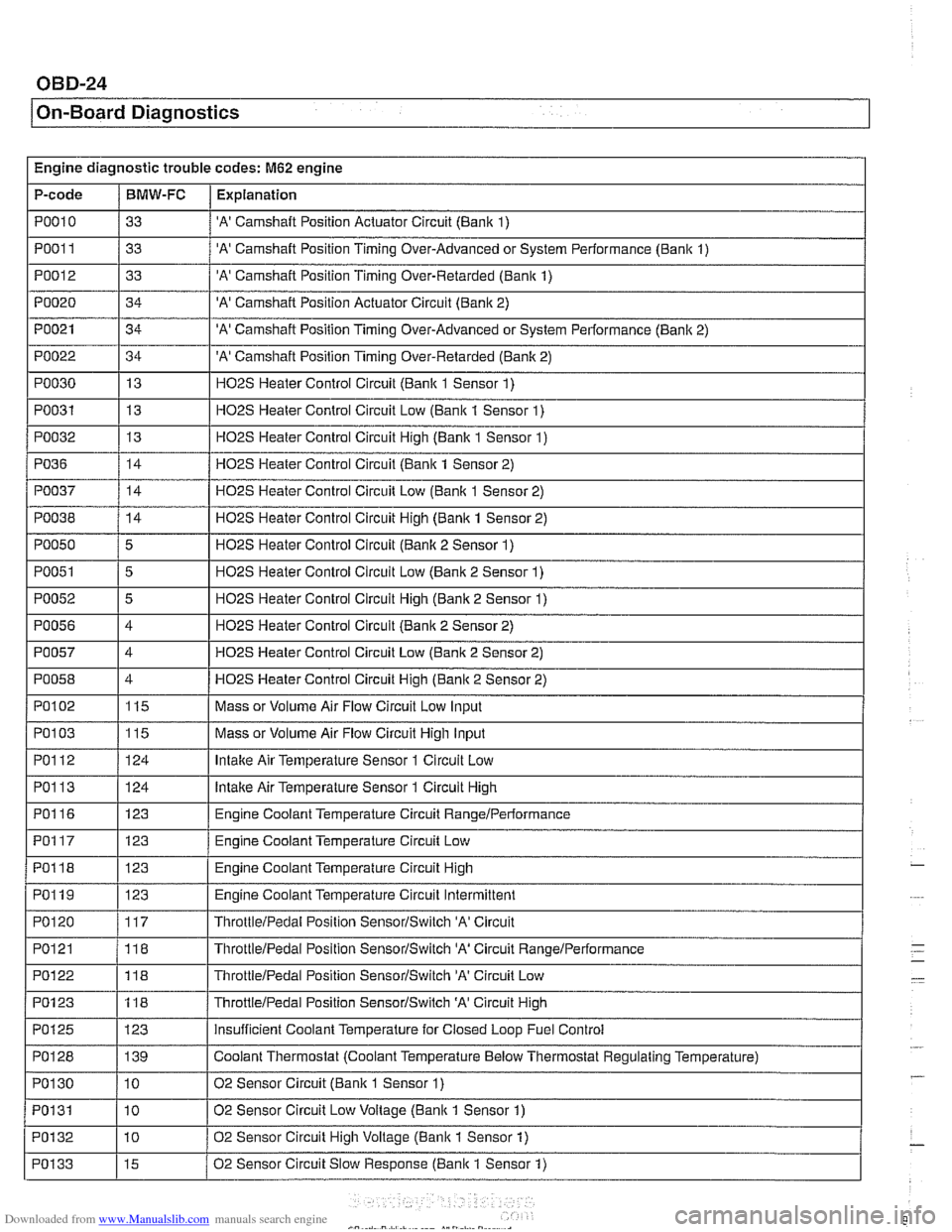
Engine diagnostic trouble codes: M62 engine
P-code
PO01 1
PO012
PO020
PO021
PO022
PO030
PO031
PO032
I I
PO038 / 14 I H02S Heater Control Circuit High (Bank 1 Sensor 2)
PO010 / 33 / 'A' Camshaft Position Actuator Circuit (Bank 1)
BMW-FC
I I -.
Explanation
33
33
34
34
34 13
13
13
PO36
'A' Camshaft Position Timing Over-Advanced or System Performance (Bank 1)
'A' Camshaft Position Timing Over-Retarded (Bank 1)
'A' Camshaft Position Actuator Circuit (Bank 2)
'A' Camshaft Position Timing Over-Advanced or System Performance (Banlc 2)
'A' Camshaft Position Timing Over-Retarded (Banlc 2)
H02S Heater Control Circuit (Bank 1 Sensor 1)
H02S Heater Control Circuit Low (Bank 1 Sensor 1)
HOPS Heater Control Circuit Hiqh (Banlc 1 Sensor 1)
PO050
PO051
PO052
PO056
PO057
PO058
PO037 / 14 / H02S Heater Control Circuit Low (Bank 1 Sensor 2)
14
I I -.
Ir-1 ThrottleIPedal Position SensorISwitch 'A' Circuit
Low-
HO2S Heater Control Circuit (Bank 1 Sensor 2)
5
5
5
4
4
4
PO102
PO1 13
PO116
PO117
PO118
PO119
PO120
PO121
H02S Heater Control Circuit (Banlc 2 Sensor 1)
H02S Heater Control Circuit Low (Bank 2 Sensor 1)
H02S Heater Control Circuit High (Bank 2 Sensor 1)
H02S Heater Control Circuit (Bank 2 Sensor 2)
HO2S Heater Control Circuit Low (Bank 2 Sensor 2)
HO2S Heater Control Circuit Hiqh (Bank 2 Sensor 2)
PO103 1115 I Mass or Volume Air Flow Circuit High Input
115
124
123
123
123
123
117
118
PO1 23
PO125
PO128
PO1 30
PO131
POI 32
PO133
Mass or Volume Air Flow Circuit Low Input
lntalte Air Temperature Sensor 1 Circuit High
Engine Coolant Temperature Circuit
RangeIPerlormance
Engine Coolant Temperature Circuit Low
Engine Coolant Temperature Circuit High
Engine Coolant Temperature Circuit Intermittent
ThrottleIPedal Position SensorISwitch 'A' Circuit
ThrottieIPedal Position SensorISwitch 'A' Circuit RanqeIPerformance
118
123 139
10
10
10
15
ThrottleIPedai Position SensorlSwitch 'A' Circuit High
insufficient Coolant Temperature for Closed Loop Fuel Control
Coolant Thermostat (Coolant Temperature Below Thermostat Regulating Temperature)
02 Sensor Circuit (Bank
1 Sensor 1)
02 Sensor Circuit Low Voltage (Bank 1 Sensor 1)
02 Sensor Circuit High Voltage (Bank
1 Sensor 1)
02 Sensor Circuit Slow Response (Bank 1 Sensor
1)
Page 992 of 1002
Downloaded from www.Manualslib.com manuals search engine
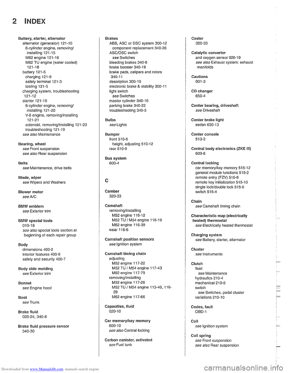
2 INDEX
Battery, starter, alternator
alternator (generator)
121-10
6-cylinder engine, removingi
installing 121-15
M62 engine 121-16
M62 TU engine (water cooled)
121-18
battery
121-5 charging 121-9
safety terminal 121-3
testing 121-5 charging system, troubleshooting
121-12
starter
121-1 9
6-cylinder engine, removingi instaliinq 121-20 . V-8 engine, rernovinglinsialiing
121-21
solenoid, removinglinstalling
121-23 troubleshooting 121-19
see also Maintenance
Bearing, wheel
see Front suspension
see also Rear suspension
Belts see Maintenance, drive belts
Blade, wiper
see Wipers and Washers
Blower motor see
A/C
BMW emblem
see Exterior trim
BMW special tools 010-18 see also special tools section at
beginning
of each repair group
Body dimensions 400-2
interior features
400-9 salety and security 400-7
Body side molding
see Exterior trim
Bonnet see Engine hood
Boot see Trunk
Brake fluid
020-24, 340-8
Brake fluid pressure sensor
340-30
Brakes
ABS, ASC or DSC system
300-12
component replacement 340-26
ASCIDSC switch
see Switches
bleeding
bralces 340-8
brake booster 340-1 9 bralce Dads. caiioers and rotors ,., 340-1 1
descriotion 300-10
e~ectrdnic brake & stability 300-11
light switch
see Switches
master cylinder
340-16 pariking brake 340-22
troubleshooting 340-5
Bulbs see Lights
Bumper
lront 510-6 height, adjusting 510-12
rear 510-9
Bus system
600-4
Camber
320-33
Camshaft
removingiinslaiiing
M52 engine 116-12
M52 TU
/ M54 engine 116-1 9 M62 engine 11 6-39
wear
116-6
Camshaft position sensors
see ignition system
Camshaft timing chain
adjusting M52 engine
117-22
M52 TU I M54 engine 117-43
M62 engine 117-79 removinglinstalling
M52 engine 117-26
M52TU 1 M54 engine 113-46.116-
28
M62 engine 117-66
Capacities, fluid
020.10
Car rnemorvlicev memorv . . 600-10
see also Centrai
lociking
Carbon canister, activated
see Fuel
tank
Caster
320-33
Catalytic converter and oxygen sensor 020-19
see also Exhaust system: exhaust
manilolds
Cautions
001-3
CD changer
650-4
Center bearing, driveshaft
see Driveshait
Center brake light
sedan
630-13
Center console
513-3
Centrai body electronics (ZKE 111)
600-6
Central locking
car memoryiey memory 515.12 general module iunctions 515-2
remote entry (FZV) 515-8
remote lkey initialization 515-10 single lociddouble ioclk 515-6
switch 515-4
Chain
see Camshaft liming chain
Characteristic map (electrically heated) thermostat
see Electrically heated thermostat
Charging system
see Battery, starter, alternator
Cluster see instruments
Clutch fluid see Maintenance
hydraulics
210-4
mechanical 210-9
switch
see Switches, pedal ciuster
variations
210.10
Codes, fault OED-1
Coil
see Ignition system
Coil spring
see Front suspension
see also Rear
suspe nsion
Page 994 of 1002
Downloaded from www.Manualslib.com manuals search engine
4 INDEX
Door window anti-trap
512-4 convenience openinglclosing 512.4
regulator and motor 512-1 1
service
512-5 switches 512-3
see also Switches
Double
VANOS see VANOS
Drive
axle
CV joint 331-15 CV joint boot 331-15
rernovinglinstalling 331-14
Drive belt
see Maintenance
Driveabiiity troubleshooting
100-4
Driveaway protection
see EWS (eiectronic immobilization)
Driveshaft aligning
260-7
center bearing, replacing 260-12 CV joint, replacing 260-14
itex-disc, replacing 260-1 1
iront centering guide, replacing 260-13
rernovinglinstailing 260-6
lroubleshooting 260-3
U-joint 260-3
DSC
see Braires
DTC (diagnostic trouble code)
OBD-8
DWA
see Anti-theft alarm
ECM (engine control module)
see 130 under appropriate
iuei
injection system
ECT (engine coolant temperature)
sensor see 130 under appropriate
iuei
injection system
EDK adaptation
130-69
MS 43.0 130-35
EHC see Electronic iieigiit control (EHC)
Electric cooling fan
see Cooling system, cooling
fan
see also Cooiing system, eiectric fan
Electrical switches
see Switches
Electrical system abbreviations
600-14 bus System 600-4
component location table 610-3
components
photos
610-36
Sport Wagon 610-81 engine 121-2
troubleshooting 600-15
voltage and polarily 600-5 wire color codes 600-12
wiring diagrams 600-12
Electrical wiring diagrams
ELE-1
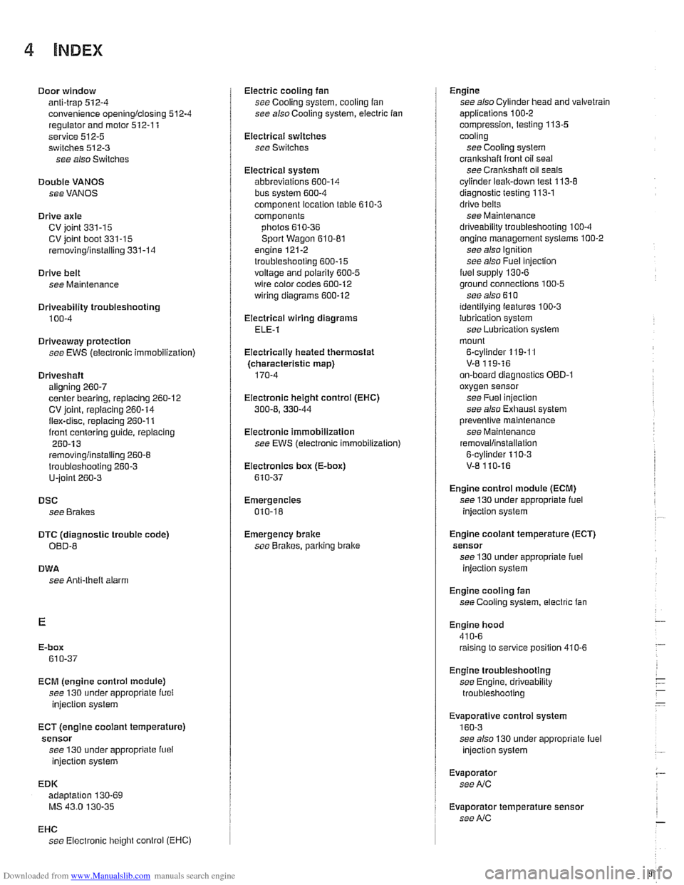
Eiectricaliy heated thermostat
(characteristic map)
170-4
Eiectronic height control (EHC)
300-8, 330-44
Eiectronic immobilization
see EWS (electronic immobilization)
Eiectronics box
(E-box)
610-37
Emergencies
010-18
Emergency brake see
BraBes, parking brake Engine
see also Cylinder head and valvetrain
applications
100-2
compression, testing 113-5
cooling see Cooiing system
crankshaft front oil seai
see Crankshaft oil seals
cyiinder leak-down test 113-8
diagnostic testing 113-1
drive belts
see Maintenance
driveability troubleshooting
100-4
engine management systems 100-2
see also Ignition
see also Fuel injection
fuel supply
130-6
ground connections 100-5
see also 61 0 identilying ieatures 100-3
lubrication svstem
see
~ubricetion system
mount
on-board diagnostics
OBD-I
oxygensensor
see Fuel injection
see also Exhaust system
Dreventive maintenance
see Maintenance
removal/installation
Engine control module (ECM)
see 130 under appropriate iuel
injection system
Engine cooiant temperature (ECT)
sensor see 130 under appropriate iuel
injection
system
Engine cooling fan
see Cooiing system, electric fan
Engine hood
41
0-6 raising to service position 410-6
Engine troubleshooting
see Engine, driveability troubleshooting
EVa~oratiVe control svstem
160-3 see also 130 under aDDroDriate iuel
injection system
Evaporator see
NC
Evaporator temperature sensor see
NC
Page 1000 of 1002
Downloaded from www.Manualslib.com manuals search engine
Steering description 300-10
liuid see Maintenance
gearbox
320-25
idler arm 320-30
lock 320-12
pitman arm 320-28 power steering pump 320-17
rack & pinion 320-19
steering column 320-10 motors 320-16
removinglinstalling 320-14
trim 320-10
steerino wheei 320-7 tie rods-
6-cvlinder, reelacinq 320-22
V- center tie' rod, replacing 320-32
variations 310-5
Steering box
see Steering, gearbox
Steering column switches
see Switches
Steering column
see Steering
Steering lock
see Steering
Steering
wheei switches
see Switches
Stepper motor
see
AIC
Steptronic transmission
see Gearshift
Strut see Front suspension
see also Rear suspension
Subframe see Rear suspension
Sunroof initializing
540-2
adiustinq 540-5 . . cornponents, removingiinstailing
540-9
emergency closing 540-4
Suspension, front
see Front suspension
see also
Aluminum suspension
cornponents
Suspension, rear
see Rear suspension
see also Aluminum suspension
cornponents
Swing arm
see Rear suspension, suspension
arms
Switches
ASCIDSC 612-12 back-ue
manual transmission 230-8
automatic transmission, see
Automatic transmission, range
switch
center console switches
612-11
central ioci(ing 612-1 1
hazard 612-1 I headlight 612-9
ignition cylinder 320-1 1. 612-6
outside mirror 612-11
pedal cluster switches 612-8 seat heater 612.12
steering column positioning 612-7
steering column switches 612-6 steering wheel switches 612-2
turn signaliheadlight dimmer 612-6
window 612-1 1
wipers 612-6
Tailgate
412-6 emergency release 400-4,412-6,
515-21
taiigatelrear window
loclring 515-14 see also Trunldtaiioate ioclr - see also Central ioclcing
Taillights
see Lights
Tape player
650-3
TCM (transmission control module)
see Automatic transmission
Tension strut
see Front suspension
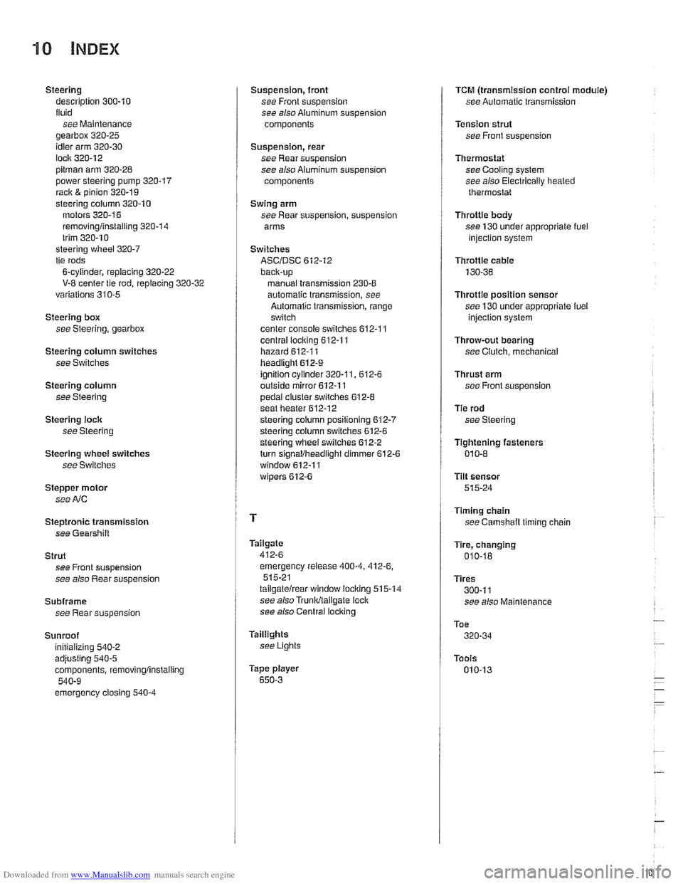
Thermostat see Cooling system
see also Electrically heated
thermostat
Throttie body
see 130 under appropriate
fuel injection system
Throttie
cable
130-38
Throttie position sensor
see 130 under appropriate luel
injection system
Throw-out bearing
see Clutch, mechanical
Thrust arm
see Front suspension
Tie rod
see Steering
Tightening fasteners
010-8
Tilt sensor 515-24
Timing chain
see
Camshaft timing chain
Tire, changing
010-18
Tires
300-1 1
see also Maintenance
Toe
320-34
Tools
010-13