warning BMW 528i 1997 E39 Workshop Manual
[x] Cancel search | Manufacturer: BMW, Model Year: 1997, Model line: 528i, Model: BMW 528i 1997 E39Pages: 1002
Page 649 of 1002
Downloaded from www.Manualslib.com manuals search engine
Front Suspension
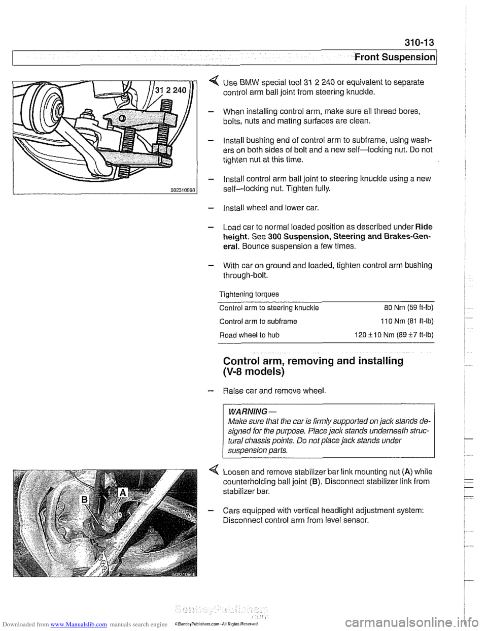
< Use BMW special tool 31 2 240 or equivalent to separate
control arm ball joint from steering ltnuckle.
- When installing control arm, make sure all thread bores.
bolts, nuts and mating surfaces are clean.
- Install bushing end of control arm to subframe, using wash-
ers on both sides of bolt and a new self-locking nut. Do not
tighten nut at this time.
- Install control arm ball joint to steering lknucltle using a new
self-locking nut. Tighten fully.
- Install wheel and lower car.
- Load car to normal loaded position as described under Ride
height. See
300 Suspension, Steering and Brakes-Gen-
eral. Bounce suspension a few times.
- With car on ground and loaded, tighten control arm bushing
through-bolt.
Tightening torques
Control arm to steering ltnuckle
80 Nm (59 ft-lb)
Control arm to subframe 110 Nm (81 It-lb)
Road wheel to hub 120ilO Nm (8957 it-lb)
Control arm, removing and installing
(V-8 models)
- Raise car and remove wheel
WARNING-
Make sure that the car is firmly supported on jack stands de-
signed for the purpose. Place jack stands underneath struc-
tural
cliassis points. Do not place jack stands under
suspension parts.
Loosen and remove stabilizer bar link mounting nut
(A) while
counterholding ball joint
(B). Disconnect stabilizer link from
stabilizer bar.
- Cars equipped with vertical headlight adjustment system:
Disconnect control arm from level sensor.
Page 652 of 1002
Downloaded from www.Manualslib.com manuals search engine
I Front Suspension
Tension strut, removing
and installing
- Raise car and remove wheel.
WARNING-
Make sure that the car is firmly supported on jack stands de-
signed for the purpose. Place jack stands underneath struc-
tural chassis points. Do not place
jack stands under
suspension parts.
- Remove engine splash shield
6-cylinder models: Remove
brake cooling duct.
V-8 models: Detach stabilizer bar from front subframe.
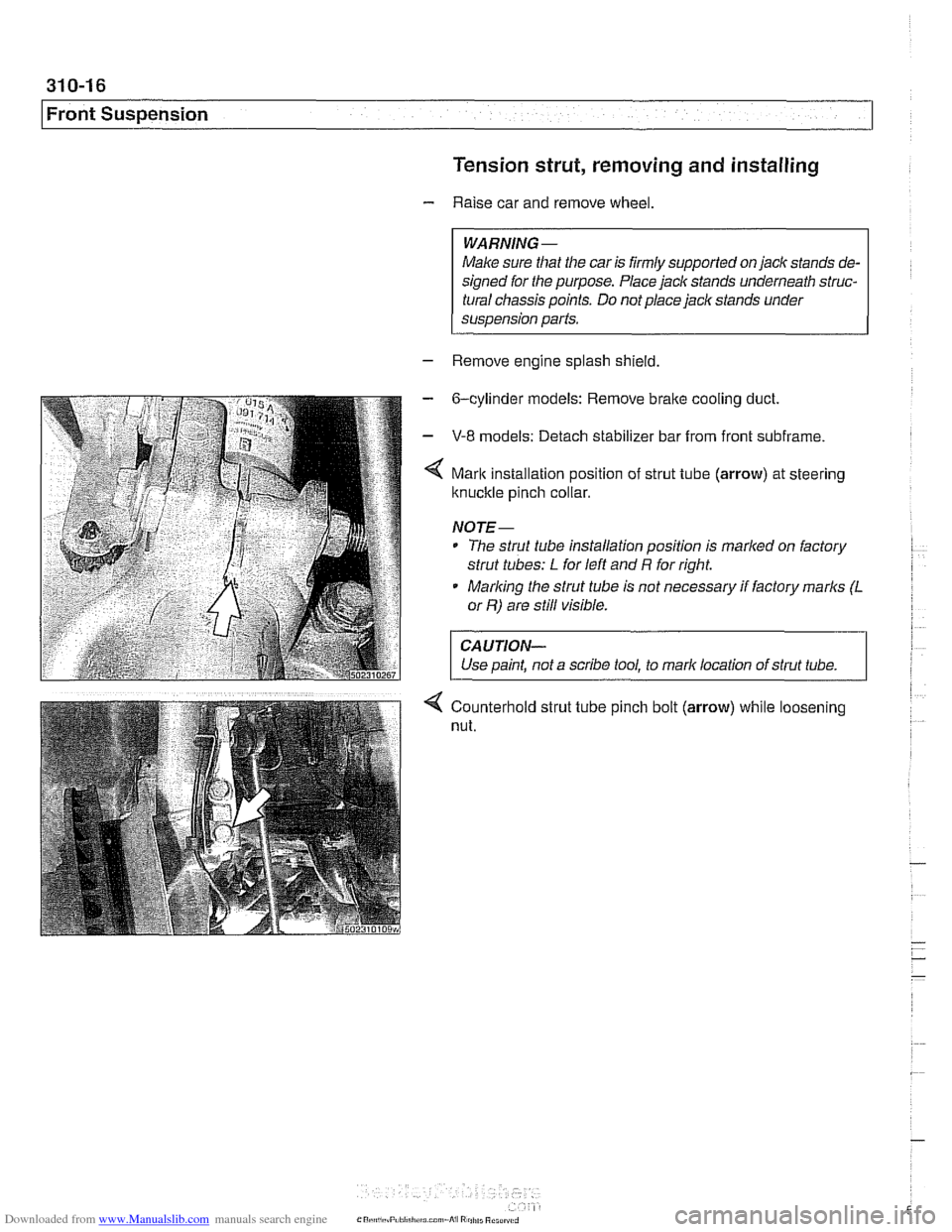
Mark installation position of strut tube (arrow) at steering
ltnuckle pinch collar.
NOJE-
* The strut tube installation position is marlted on factory
strut tubes:
L for left and R for right.
* Marlting the strut tube is not necessary if factory marks (L
or R) are still visible.
CAUJION-
Use paint, not a scribe tool, to mark location of strut tube. 1
4 Counterhold strut tube pinch bolt (arrow) while loosening
nut.
Page 654 of 1002
Downloaded from www.Manualslib.com manuals search engine
31 0-1 8
I~ront Suspension Tension strut bushing, replacing
- Raise car and remove wheel.
WARNING-
Make sure that the caris firmly supported on jack stands de-
signed for the purpose. Place jack stands underneath struc-
tural chassis points. Do
not place jack stands under
suspension parts.
- Remove tension strut from car as described earlier.
- Using a service press and appropriate press tools (BMW
special tools 31 2 26112621263 or equivalent), press bushing
out of tension strut.
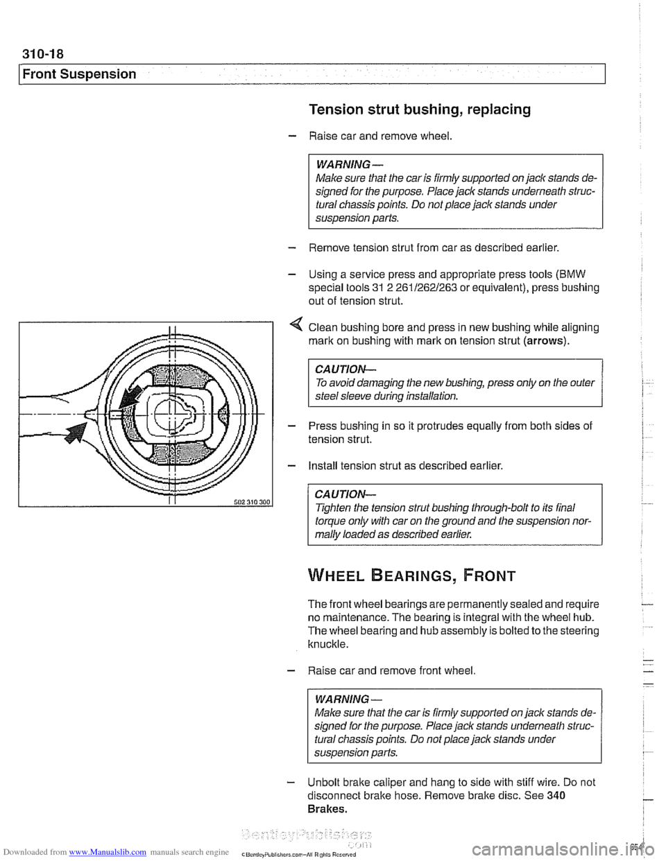
4 Clean bushing bore and press in new bushing while aligning
mark on bushing with
rnarlt on tension strut (arrows).
CAUTION-
To avoid damaging the new bushing, press only on the outer
steel sleeve during installation.
- Press bushing in so it protrudes equally from both sides of
tension strut.
- Install tension strut as described earlier.
CAUTION-
Tighten the tension strut bushing through-bolt to its final
torque only with car on the ground and the suspension nor-
mally loaded as described earlier.
The front wheel bearings are permanently sealed and require
no maintenance. The bearing is integral with the wheel hub.
The wheel bearing and hub assembly is bolted to the steering
knuckle.
- Raise car and remove front wheel
WARNING-
Make sure that the car is firmly supported on jack stands de-
signed for the purpose. Place jack stands underneath struc-
tural chassis points. Do not place
jack stands under
susoension Darts.
- Unbolt brake caliper and hang to side with stiff wire. Do not
disconnect bralte hose. Remove bralte disc. See
340
Brakes.
Page 659 of 1002
Downloaded from www.Manualslib.com manuals search engine
1 320 Steering and Wheel Alignment
General ........................... .32 0.2
Special tools
........................ .32 0.2
Steering system
..................... .32 0.4
Steering system variations
............. .32 0.5
Steering system warnings and cautions
... .32 0.6
Steering Wheel .................... .32 0.7
Steering wheel. removal and installation
.. .32 0.7
Steering Column ................. .32 0.1 0
Steering column components .......... .32 0.10
Steering column trim, removing
and replacing
...................... .32 0.10
lgnition switch ring antenna (EWS).
removing and installing
............... .32 0.1 1
lgnition lock cylinder.
removing and installing
............... .32 0-1 1
Steering column lock. removing
and installing
....................... .32 0.12
lgnition
interloclc cable. removing and installing
(models with automatic transmission)
... .32 0.13
Interlock cable. adjusting
(models with automatic transmission)
... .32 0.14
Steering column. removing and installing
. .32 0.14
Steering column adjustment motors.
removing and installing
............... .32 0.16
Power Steering Pump ............. .32 0.17
Power steering pump. removing
and installing
....................... .32 0.1 7
Power steering system.
bleeding and filling
.................. .32 0.18
Rack and Pinion Steering
(6-cylinder models)
............... 320-19
Rack and pinion steering components
(6-cylinder models)
.................. 320-1 9
Steering rack. removing and installing
.... 320-19
Steering
rack boot. replacing ........... 320-22
Tie rod (outer). replacing
.............. 320-22
Tie rod (inner). replacing
.............. 320-23
Steering Gearbox (V-8 models) .... 320-24
Steering gearbox system components
. .
(V-8 models) ....................... 320-24
Steering gearbox, removing and installing 320-25
Pitman arm. removing and installing ..... 320-28
Pitman arm. adjusting ................ 320-29
Steering idler arm. removing
and installing
....................... 320-30
Idler arm bushing. replacing ........... 320-31
Center tie rod. replacing
.............. 320-32
Wheel Alignment .................. 320-33
Camber
........................... 320-33
Caster
............................ 320-33
Front toe and toe difference angle
....... 320-34
Reartoe ........................... 320-34
Preparing for alignment
............... 320-35
Alignment specifications tables
......... 320-35
Page 664 of 1002
Downloaded from www.Manualslib.com manuals search engine
Steering and Wheel Alignment
Steering system warnings and cautions
WARNING -
The BMW airbag system is complex. Special precautions
must be observed when servicing the system. Serious in-
jury may result if system service is attempted by persons
unfamiliar with the BMW
airbag system and its approved
service procedures. BMW specifies that all inspection and
service should be
peiformed by an authorized BMW deal-
e,:
The BMW E39 is equipped with an airbag mounted in
the steering wheel. The
airbag is an explosive device
and should be treated with extreme caution. Always fol-
low the
airbag removal procedure as outlined in 721
Airbag System (SRS).
BMW airbags are equipped with a bacli-up power sup-
ply inside the
airbag control module. A 5 second wait-
ing period should be observed after the battery cable
has been disconnected. This will allow the reserve
power supply to discharge.
Do not reuse self-locking nuts. They are designed to
be used only once and may fail if reused. Always re-
place them with new locliing nuts.
* Do not install bolts and nuts coated with undercoating
wax, as correct tightening torque cannot be assured.
Always clean the threads with solvent before installa-
tion, or install new parts.
Do not attempt to weld or straighten any steering com-
ponents. Always replace damagedparts.
CAUTION--
- Some E39 models are equipped with aluminum suspen.
sion components. The following cautions apply:
Due to the chemical and corrosion characteristics of
aluminum, do not bring into contact with battery acid.
Do not clean with wire brushes with brass or iron bris-
tles. Only use brushes with stainless steel bristles.
Do
not expose to flying sparks from grindinghutting op-
erations.
Do not subject to steel welding splashes.
* Do not expose to temperatures over 80% (176°F).
even for short periods. Temperatures in painting iacili-
ties are not a problem.
Page 665 of 1002
Downloaded from www.Manualslib.com manuals search engine
320-7
Steering and Wheel ~liqnmentl
STEERING WHEEL
Steering wheel, removal and installation
WARNING -
The BMWairbag system (Supplemental Restraint System or
SRS) is complex. Special precautions must be observed
when servicing. Serious injury may result if
SRS system serv-
ice is
attempted by persons unfamiliar with the BMW SRS
and its approved service procedures. BMW specifies that all
inspection andservice should be preformed by an authorized
BMW dealer.
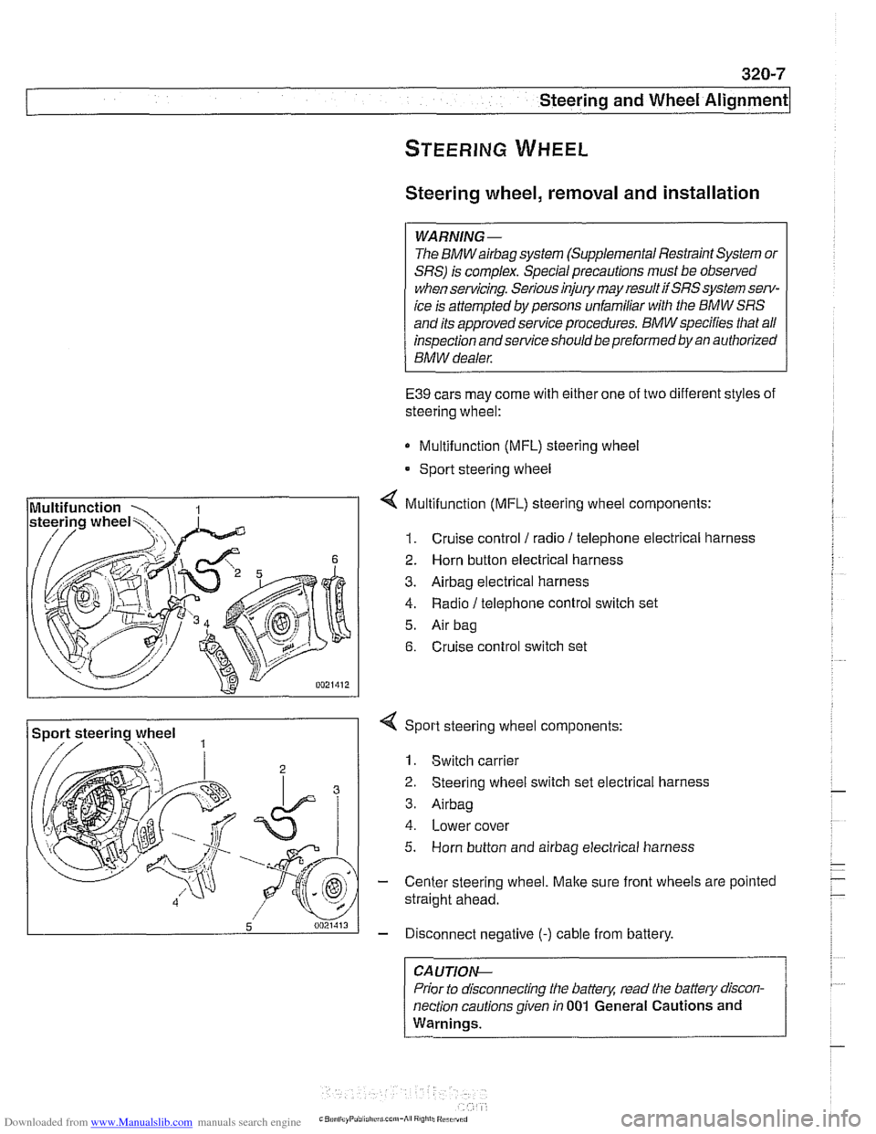
E39 cars may come with either one of two different styles of
steering wheel:
Multifunction (MFL) steering wheel
* Sport steering wheel
4 Multifunction (MFL) steering wheel components:
1. Cruise control 1 radio 1 telephone electrical harness
2. Horn button electrical harness
3. Airbag electrical harness
4. Radio / telephone control switch set
5. Air bag
6. Cruise control switch set
Sport steering wheel
3
5 0021413
4 Sport steering wheel components:
1. Switch carrier
2 Steering wheel switch set electrical harness
3. Airbag
4. Lower cover
5. Horn button and airbag electrical harness
- Center steering wheel. Make sure front wheels are pointed
straight ahead.
- Disconnect negative (-) cable from battery.
CA UTIOP&
Prior to disconnecting the battern read the battew discon-
nection cautions given in
001 General Cautions and
Warnings.
-
Page 669 of 1002
Downloaded from www.Manualslib.com manuals search engine
Steering and Wheel ~li~nrnentl
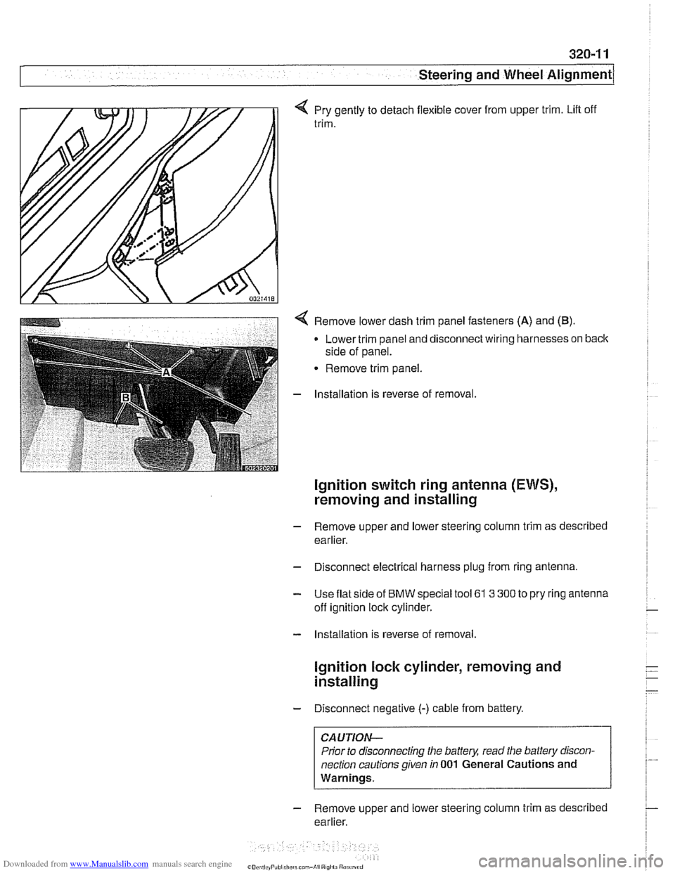
q Pry gently to detach flexible cover from upper trim. Lift off
trim.
< Remove lower dash trim panel fasteners (A) and (B).
Lower trim panel and disconnect wiring harnesses on back
side of panel.
Remove trim panel.
- Installation is reverse of removal.
Ignition switch ring antenna (EWS),
removing and installing
- Remove upper and lower steering column trim as described
earlier.
- Disconnect electrical harness plug from ring antenna.
- Use flat side of BMW special tool 61 3 300 to pry ring antenna
off ignition lock cylinder.
- Installation is reverse of removal.
lgnition lock cylinder, removing and
installing
- Disconnect negative (-) cable from battery.
CAUTION-
Prior to disconnecting the battery, read the battery discon-
nection cautions given
in 001 General Cautions and
Warnings.
- Remove upper and lower steering column trim as described
earlier.
Page 670 of 1002
Downloaded from www.Manualslib.com manuals search engine
I Steering and Wheel Alignment
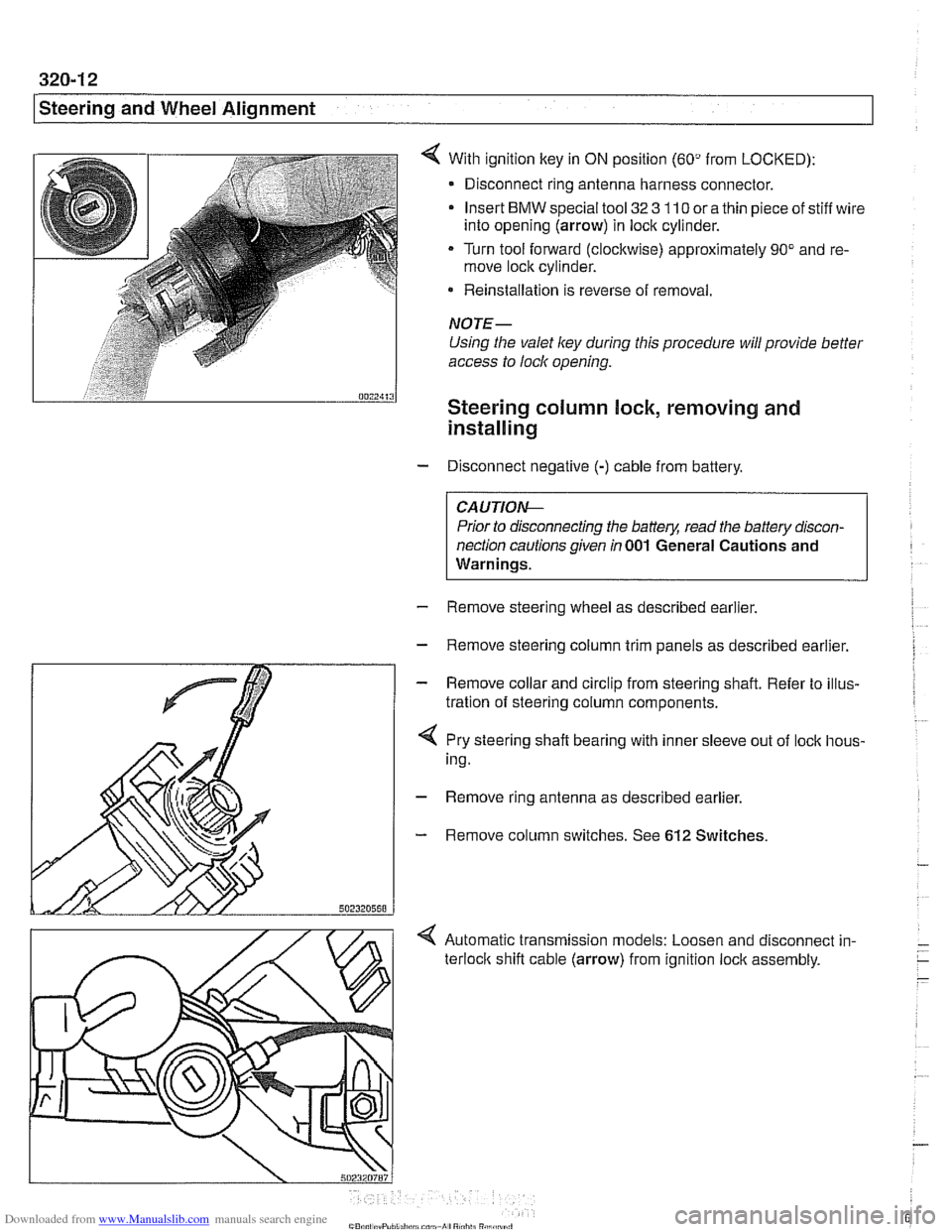
With ignition key in ON position (60" from LOCKED):
- Disconnect ring antenna harness connector.
Insert
BMW special tool 32 3 110 or a thin piece of stiff wire
into opening (arrow) in lock cylinder.
Turn tool forward (clockwise) approximately 90" and re-
move lock cylinder.
* Reinstallation is reverse of removal.
NOTE-
Using the valet ley during this procedure will provide better
access to lock opening.
Steering column lock, removing and
installing
- Disconnect negative (-) cable from battery.
CAUTIO&
Prior to disconnecting the battery, read the battery discon-
nection cautions given
in 001 General Cautions and
Warnings.
- Remove steering wheel as described earlier.
- Remove steering column trim panels as described earlier.
- Remove collar and circlip from steering shaft. Refer to illus-
tration of steering column components.
4 Pry steering shaft bearing with inner sleeve out of lock hous-
ing.
- Remove ring antenna as described earlier.
- Remove column switches. See 612 Switches.
< Automatic transmission models: Loosen and disconnect in-
terloclc shift cable (arrow) from ignition lock assembly.
Page 675 of 1002
Downloaded from www.Manualslib.com manuals search engine
Steering and Wheel Alignment
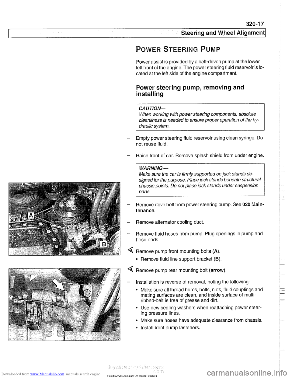
Power assist is provided by a belt-driven pump at the lower
left front of the engine. The power steering fluid reservoir is lo-
cated at the left side of the engine compartment.
Power steering pump, removing and
installing
When working with power steering components, absolute
cleanliness is needed to ensure proper operation of the hy-
- Empty power steering fluid reservoir using clean syringe. Do
not reuse fluid.
- Raise front of car. Remove splash shield from under engine.
WARNING-
Make sure the car is firmly supported on jack stands de-
signed for the purpose. Place jack stands beneath structural
chassis points. Do not place jack stands under suspension
Darts.
Remove drive belt from power steering pump. See
020 Main-
tenance.
Remove alternator cooling duct
Remove fluid hoses from pump. Plug openings in pump and
hose ends.
Remove pump front mounting bolts
(A).
Remove fluid line support bracket (B)
Remove pump rear mounting bolt (arrow)
- Installation is reverse of removal, noting the following:
Make sure all thread bores, bolts, nuts, fluid couplings and
mating
surfaces are clean, and inside surface of multi-
ribbed-belt is free of grease and dirt.
Use new sealing washers when reattaching power steer-
ing pressure lines.
Make sure hoses have adequate clearance from chassis.
Install front pump fasteners.
Page 677 of 1002
Downloaded from www.Manualslib.com manuals search engine
i Steering and Wheel Alignment
RACK AND PINION STEERING
(6-CYLINDER MODELS)
Refer to the steering components illustration when perform-
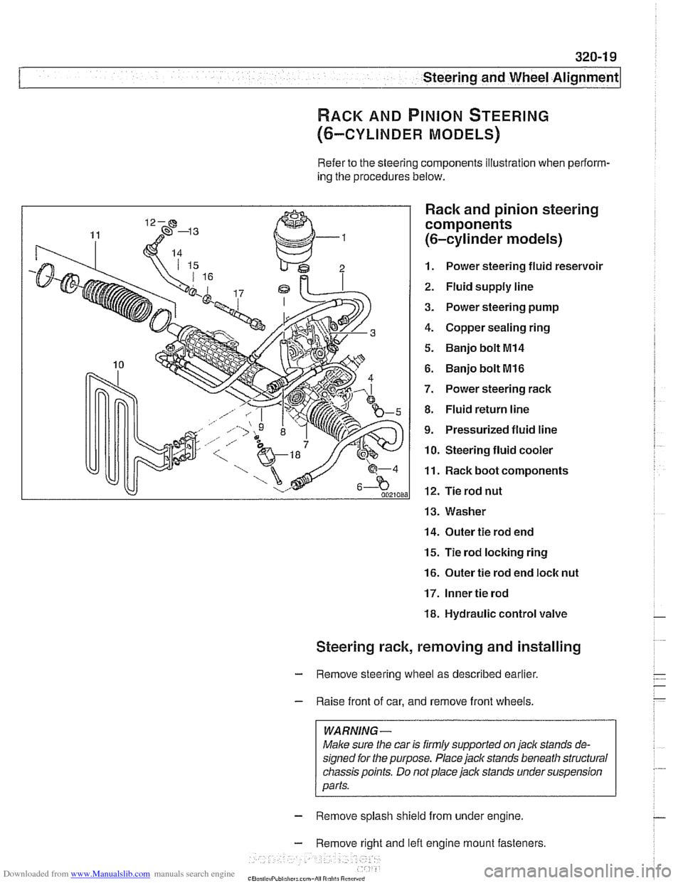
ing the procedures below.
Rack and pinion steering
components
(6-cylinder models)
1. Power steering fluid reservoir
2. Fluid supply line
3. Power steering pump
4. Copper sealing ring
5. Banjo bolt MI4
6. Banjo bolt MI6
7. Power steering rack
8. Fluid return line
9. Pressurized fluid line
10. Steering fluid cooler
11. Rack boot components
12. Tie rod nut
13. Washer
14. Outer tie rod end
15. Tie rod locking ring
16. Outer tie rod end loclc nut
17. Inner tie rod
18. Hydraulic control valve
Steering rack, removing and installing
- Remove steering wheel as described earlier.
- Raise front of car, and remove front wheels.
WARNING -
Male sure the car is firmly supported on jack stands de-
signed for the purpose. Place jack stands beneath structural
chassis points. Do
not place jack stands under suspension
parts.
- Remove splash shield from under engine.
- Remove right and lefl engine mount fasteners
-" ., - , . ,