warning BMW 528i 1997 E39 Workshop Manual
[x] Cancel search | Manufacturer: BMW, Model Year: 1997, Model line: 528i, Model: BMW 528i 1997 E39Pages: 1002
Page 574 of 1002
Downloaded from www.Manualslib.com manuals search engine
230-1 0
I Manual Transmission
Output shaft seal, replacing (5-speed
transmission) (transmission installed)
- Raise and safely support vehicle.
WARNING -
Make sure the car is stable and well supported at all times.
Use a professional automotive
lilt orjack stands designed
for the purpose.
A floorjack is not adequate support.
- Remove exhaust system and heat shields. See 180 Exhaust
System
Support transmission with transmission jack.
Disconnect driveshafi at transmission output flange, and
hang driveshaft to side. See
260 Driveshaft.
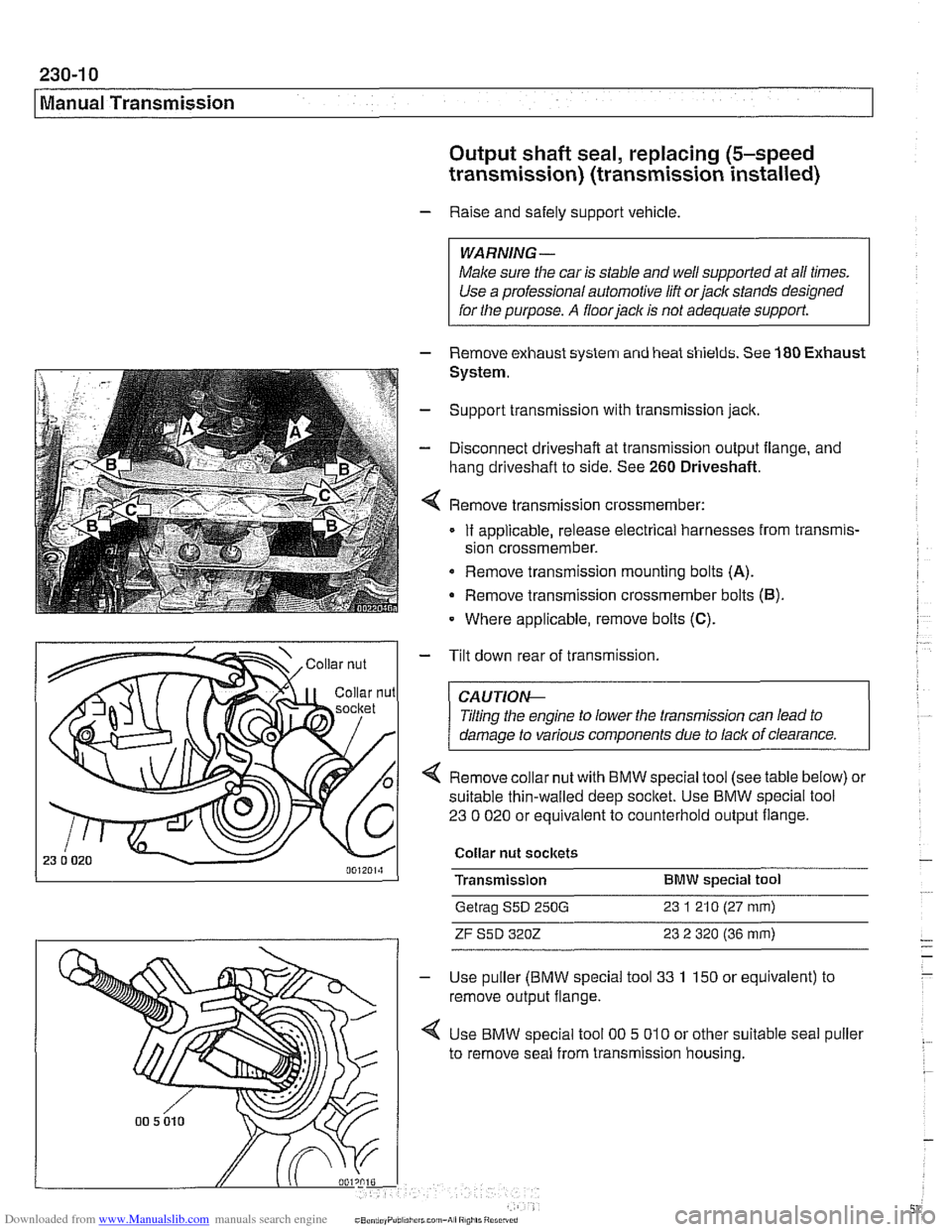
Remove transmission crossmember:
If applicable, release electrical harnesses from transmis-
sion crossmember.
Remove transmission mounting bolts
(A).
Remove transmission crossmember bolts (6).
Where applicable, remove bolts (C).
- Tilt down rear of transmission.
CAUTIOI\C
Tilting the engine to lower the transmission can lead to
damage to various components due to lack of clearance.
4 Remove collar nut with BMW special tool (see table below) or
suitable thin-walled deep
socltet. Use BMW special tool
23 0 020 or equivalent to counterhold output flange.
Collar nut sockets
Transmission
BMW special tool
Getrag S5D 250G 23 1 21 0 (27 mm)
ZF S5D 3202 23 2 320 (36 mm)
Use puller (BMW special tool 33 1 150 or equivalent) to
remove output flange.
Use BMW special tool
00 5 010 or other suitable seal puller
to remove seal from transmission housing.
Page 576 of 1002
Downloaded from www.Manualslib.com manuals search engine
230-12
/ Manual Transmission
Output shaft seal, replacing (6-speed
transmission) (transmission installed)
- Raise and safely support vehicle.
WARNING-
Make sure the car is stable and well supported at all times.
Use a professional automotive lift
orjack stands designed for
the purpose.
A floorjack is not adequate support.
- Remove exhaust system and heat shields. See 180 Exhaust
System.
- Support transmission with transmission jack
- Disconnect driveshaft at transmission output flange, and
hang driveshaft to side. See
260 Driveshaft.
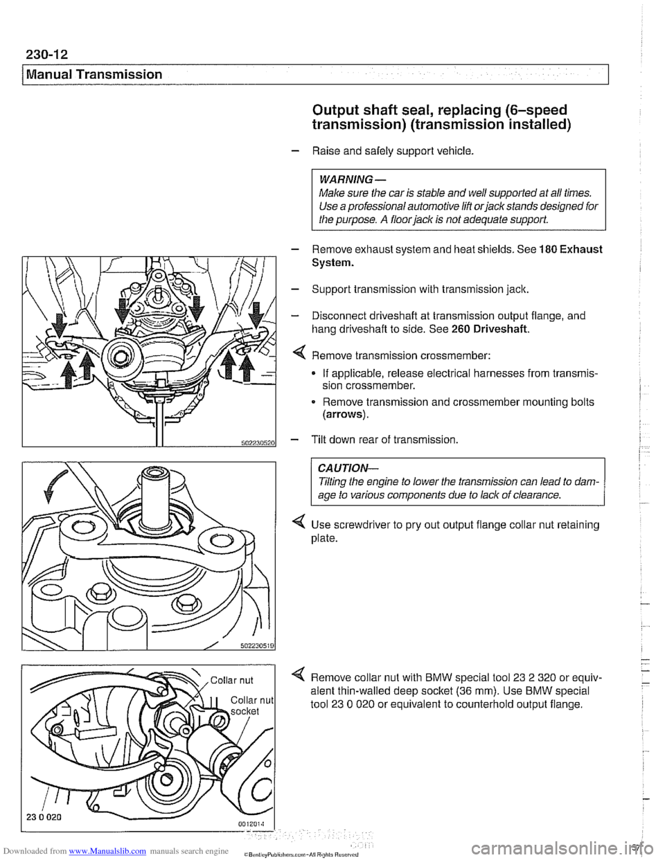
Remove transmission crassmember:
If applicable, release electrical harnesses from transmis-
sion crossmember.
Remove transmission and crossmember mounting bolts
(arrows).
5022305201 - Tilt down rear of transmission
CAUTION-
Tlting the engine to lower the transmission can lead to dam-
age to various components due to lack of clearance.
Use screwdriver to pry out output flange collar nut retaining
plate.
Remove collar nut with BMW special tool
23 2 320 or equiv-
alent thin-walled deep socltet
(36 mm). Use BMW special
tool
23 0 020 or equivalent to counterhold output flange.
Page 580 of 1002
Downloaded from www.Manualslib.com manuals search engine
Manual Transmission
- Thoroughly clean guide sleeve mounting bolts, sealing sur-
faces, and threads. Apply
Loctite8243 or equivalent thread
locking compound to guide sleeve bolts. Reinstall guide
sleeve and
spacer(s).
Tightening torques
Guide sleeve to transmission case
M6 10 Nm (89 in-lb)
* M8 x 22 18 Nm (13 ft-lb)
- Max30 25 Nm (18 ft-lb)
- Reinstall transmission.
TRANSMISSION REMOVAL AND
~NSTALLATION
Removal and installation of the transmission is best accorn-
plished on a lifl using a transmission jack.The engine must be
supported using appropriate support equipment. This allows
the engine to pivot on its mounts to access the upper
Torx-
head bolts at the bellhousing.
WARNING-
Male sure the car is stable and well supported at all times.
Use a professional aulomorive lift or jack slanos des~gned
lor the purpose. A floor jack is nor adequare supporr.
The removal of the transmission may upset the balance
of the vehicle on a
lifl.
Transmission, removing and installing
- Disconnect negative (-) cable from battery.
CAUTION-
Prior to disconnecting the battery, read the battery discon-
nection cautions given
in 001 Warnings and Cautions.
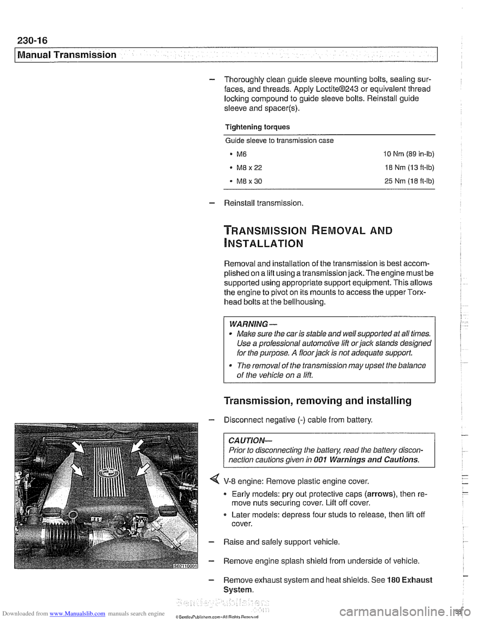
V-8 engine: Remove plastic engine cover.
Early models: pry out protective caps (arrows), then re-
move nuts securing cover. Lift off cover.
Later models: depress four studs to release, then
lift off
cover.
- Raise and safely support vehicle
- Remove engine splash shield from underside of vehicle
- Remove exhaust system and heat shields. See 180 Exhaust
System.
Page 591 of 1002
Downloaded from www.Manualslib.com manuals search engine
Automatic Transmission
- Raise and safely support vehicle.
CA U JIOG
Male sure the car is stable and well supported at all times.
Use a professional automotive lift
orjack stands designed for
the purpose. A floorjack is not adequate support
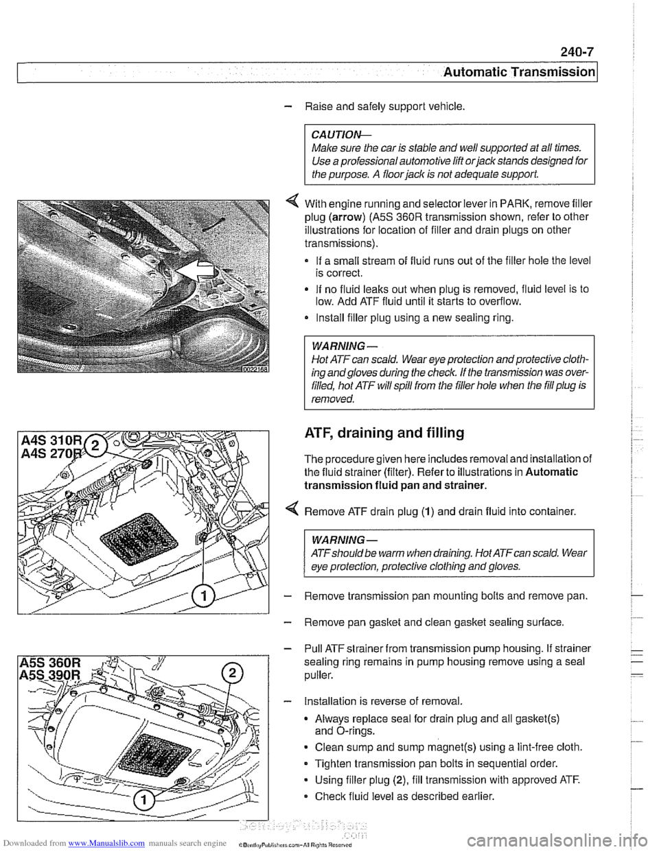
4 With engine running and selector lever in PARK, remove filler
plug (arrow)
(A5S 360R transmission shown, refer to other
illustrations for location of filler and drain plugs on other
transmissions).
If a small stream of fluid runs out of the filler hole the level
is correct.
If no fluid
leaks out when plug is removed, fluid level is to
low. Add ATF fluid until it starts to overflow.
Install filler plug using a new sealing ring.
Hot ATF can scald. Wear eye protection and protective cloth-
ing andgloves during
the check. If the tmnsmission was over-
filled, hot ATF will spill from the filler hole when the
fill plug is
removed.
ATF, draining and filling
The procedure given here includes removal and installation of
the fluid strainer (filter). Refer to illustrations in Automatic
transmission fluid
pan and strainer.
Remove ATF drain plug
(1) and drain fluid into container.
WARNING-
ATFshould be warm when draining. Hot ATFcan scald. Wear
eye protection, protective clothing and gloves.
Remove transmission pan mounting bolts and remove pan.
Remove pan gasket and clean
gasket sealing surface.
- Pull ATF strainer from transmission pump housing. If strainer
sealing ring remains in pump housing remove using a seal
puller.
- Installation is reverse of removal.
Always replace seal for drain plug and all
gasket(s)
and O-rings.
Clean sump and sump
magnet(s) using a lint-free cloth.
Tighten transmission pan bolts in sequential order.
Using filler plug
(2), fill transmission with approved ATF.
Check fluid level as described earlier.
Page 594 of 1002
Downloaded from www.Manualslib.com manuals search engine
240-1 0
Automatic Transmission
TRANSMISSION REMOVAL AND
INSTALLATION
Removal and installation of the transmission is best accorn-
plished on an automotive lift using a transmission jack. Use
caution and safe workshop practices when working beneath
car and lowering transmission.
Torx-head bolts are used to mount the transmission to the
bellhousing.
Besure to have appropriate tools on hand before
starting the job.
WARNING-
Be sure the vehicle is properly supported. The removal of the
transmission may upset the balance of the vehicle on a lift
CAUJION-
Tilting the engine to remove the transmission can lead to
damaae to various components due to
laclc of clearance. 1
Transmission, removing and installing
WARNING -
Allow engine and transmission to cool down before starting
work on the transmission.
- Disconnect negative (-) cable from battery.
CAUTION-
Prior to disconnecting the battery, read the battery discon-
nection cautions given in
001 General Cautions and
Warninas.
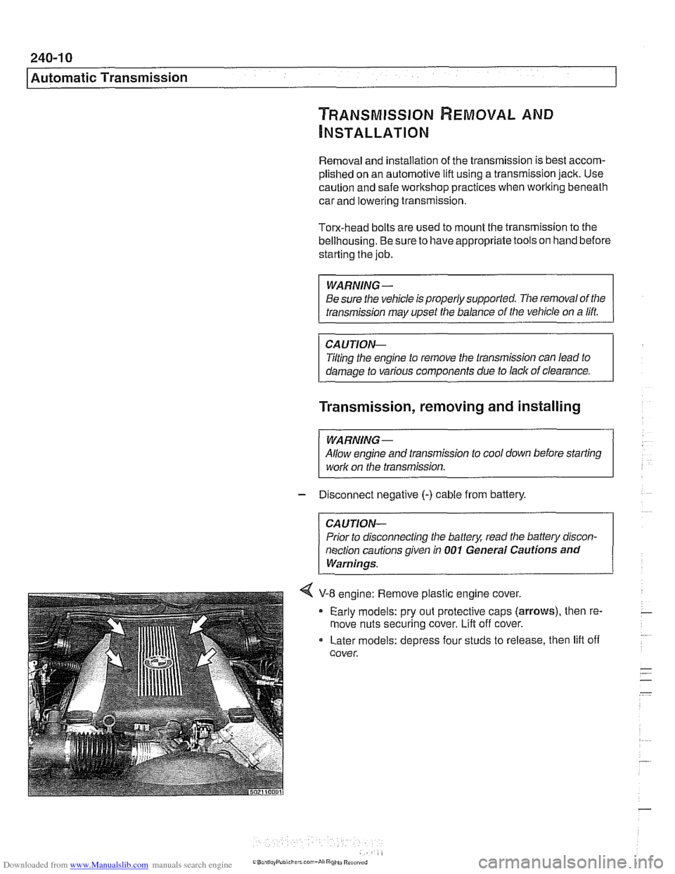
4 V-8 engine: Remove plastic engine cover.
Early models: pry out protective caps
(arrows), then re-
move nuts securing cover.
Lift off cover.
Later models: depress four studs to release, then lift off
cover.
Page 601 of 1002
Downloaded from www.Manualslib.com manuals search engine
Gearshift ~inkaael
Gearshift lever, removing
(manual transmission)
Use the accompanying illustration as a guide when removing
and installing the gearshift linkage.
- Remove shift knob by pulling knob straight off shift lever.
NOTE-
Pull up on the shift knob with about 90 lbs. of force. Do not
twist
knob or locating key can be damaged.
- Squeeze sides of shift boot to unclip from center console.
Pull boot up and off shift lever.
- Remove sound insulation at base of shift lever.
- Raise vehicle to gain access to underside of vehicle.
- --
WARNING-
Male sure the car is stable and well supported at all tfmes.
Use a professional automotwe hft orjaclc stands designed for
the purpose.
A floorjaclc 1s not adequate support.
- Remove complete exhaust system. See 180 Exhaust
System.
- Remove driveshaft. See 260 Driveshaft.
- Support transmission with transmission jack. Remove
crossmember from rear of transmission.
- Lower rear of transmission to access gearshift linkage.
CA UTIOI\C
Tilting the engine to lower the transmission can lead to
damage to various components due to lack of clearance.
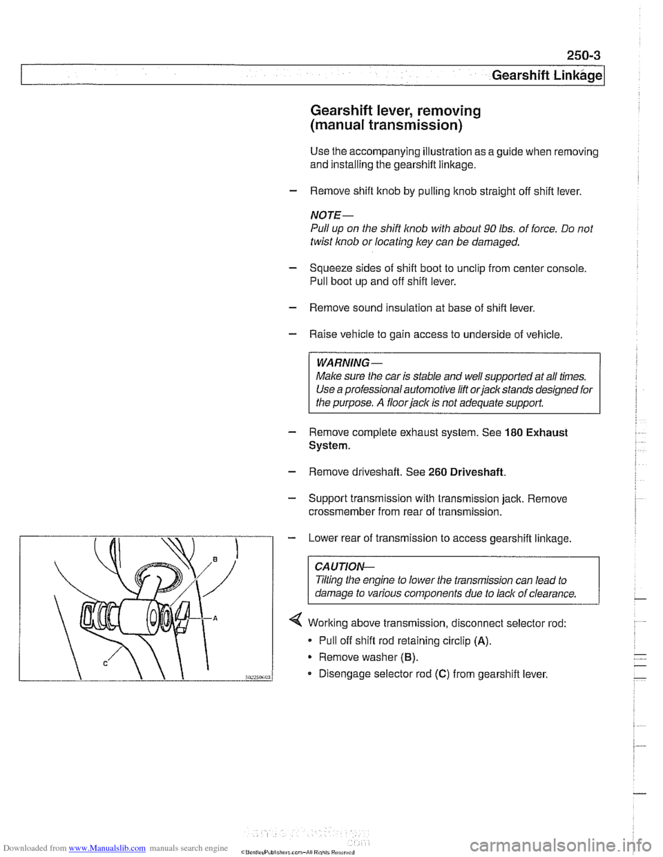
4 Working above transmission, disconnect selector rod:
* Pull off shift rod retaining circlip (A).
Remove washer (6).
Disengage selector rod (C) from gearshift lever.
Page 604 of 1002
Downloaded from www.Manualslib.com manuals search engine
pearshift Linkage
~UTOMATIC TRANSMISSION
GEARSHIFT
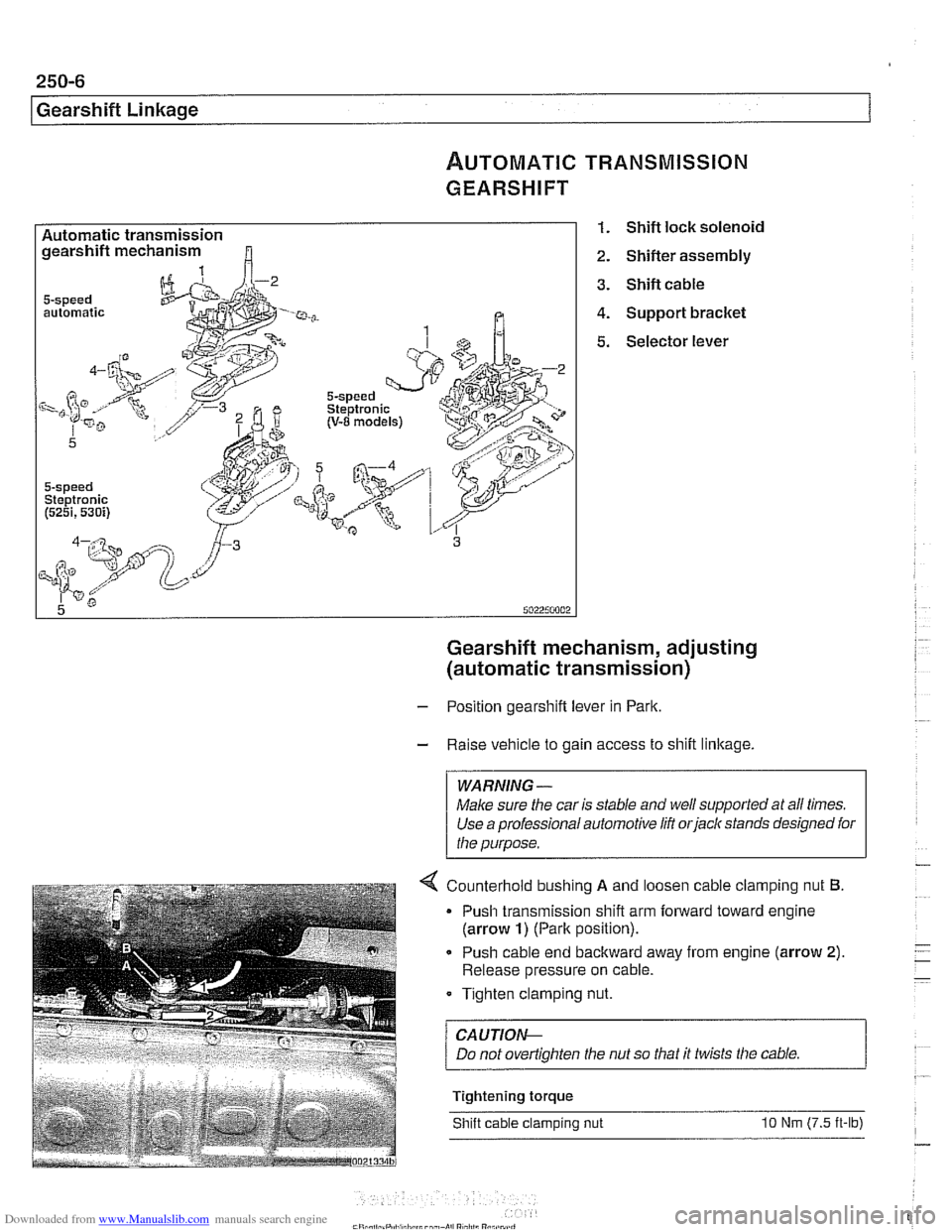
Automatic transmission gearshift mechanism
automatic
5-speed Steptronic (5251,530i)
1. Shift lock solenoid
2. Shifter assembly
3. Shift cable
4. Support bracket
5. Selector lever
Gearshift mechanism, adjusting
(automatic transmission)
- Position gearshift lever in Park.
- Raise vehicle to gain access to shift linkage.
WARNING -
Make sure the car is stable and well supported at all times.
Use a professional automotive
lift orjack stands designed for
the purpose.
4 Counterhold bushino A and loosen cable clam~ino nut 6.
Push cable end backward away from engine (arrow 2).
Release pressure on cable.
Tighten clamping nut.
/ CAUTION--
Tightening torque
Shift cable clamping nut
10 Nm (7.5 it-lb)
Page 641 of 1002
Downloaded from www.Manualslib.com manuals search engine
31 0-5
Front ~uspensionl
Front strut assembly, removing and
installing
- Raise car and remove front wheel.
WARNING-
Make sure that the car is firmly supported on jack stands de-
signed for the purpose. Place jack stands underneath struc-
tural chassis points.
Do not place jack stands under
suspension
parts.
- Unbolt bralte caliper assembly, lkeeping bralte hose connect-
ed. Secure brake caliper to body with wire. Do not let it hang
from brake hose. See
340 Brakes.
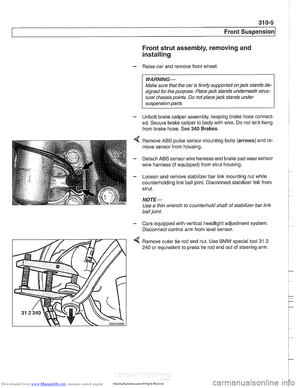
Remove ABS pulse sensor mounting bolts (arrows) and re-
move sensor from housing.
Detach ABS sensor wire harness and bralte pad wear sensor
wire harness (if equipped) from strut housing.
Loosen and remove stabilizer bar link mounting nut while
counterholding
link ball joint. Disconnect stabilizer link from
strut.
NOTE-
Use a thin wrench to counterhold shaft of stabilizer bar link
ball joint.
- Cars equipped with vertical headlight adjustment system:
Disconnect control arm from level sensor.
4 Remove outer tie rod end nut. Use BMW special tool 31 2
240 or equivalent to press tie rod end out of steering arm.
Page 643 of 1002
Downloaded from www.Manualslib.com manuals search engine
Front ~us~ensionl
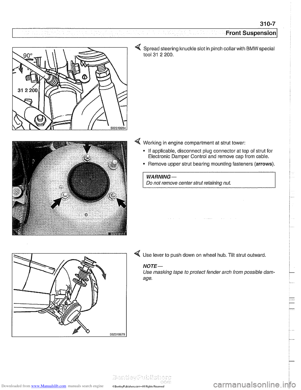
Spread steering knuckle slot in
tool
31 2 200.
pinch collarwith BMW special
4 Worlting in engine compartment at strut tower:
- If applicable, disconnect plug connector at top of strut for
Electronic Damper Control and remove cap from cable.
Remove upper strut bearing mounting fasteners
(arrows).
WARNING-
Do not remove centerstrut retaining nut.
4 Use lever to push down on wheel hub. Tilt strut outward
NOTE-
Use masking tape to protect fender arch from possible dam-
age.
Page 646 of 1002
Downloaded from www.Manualslib.com manuals search engine
31 0-1 0
Front Suspension
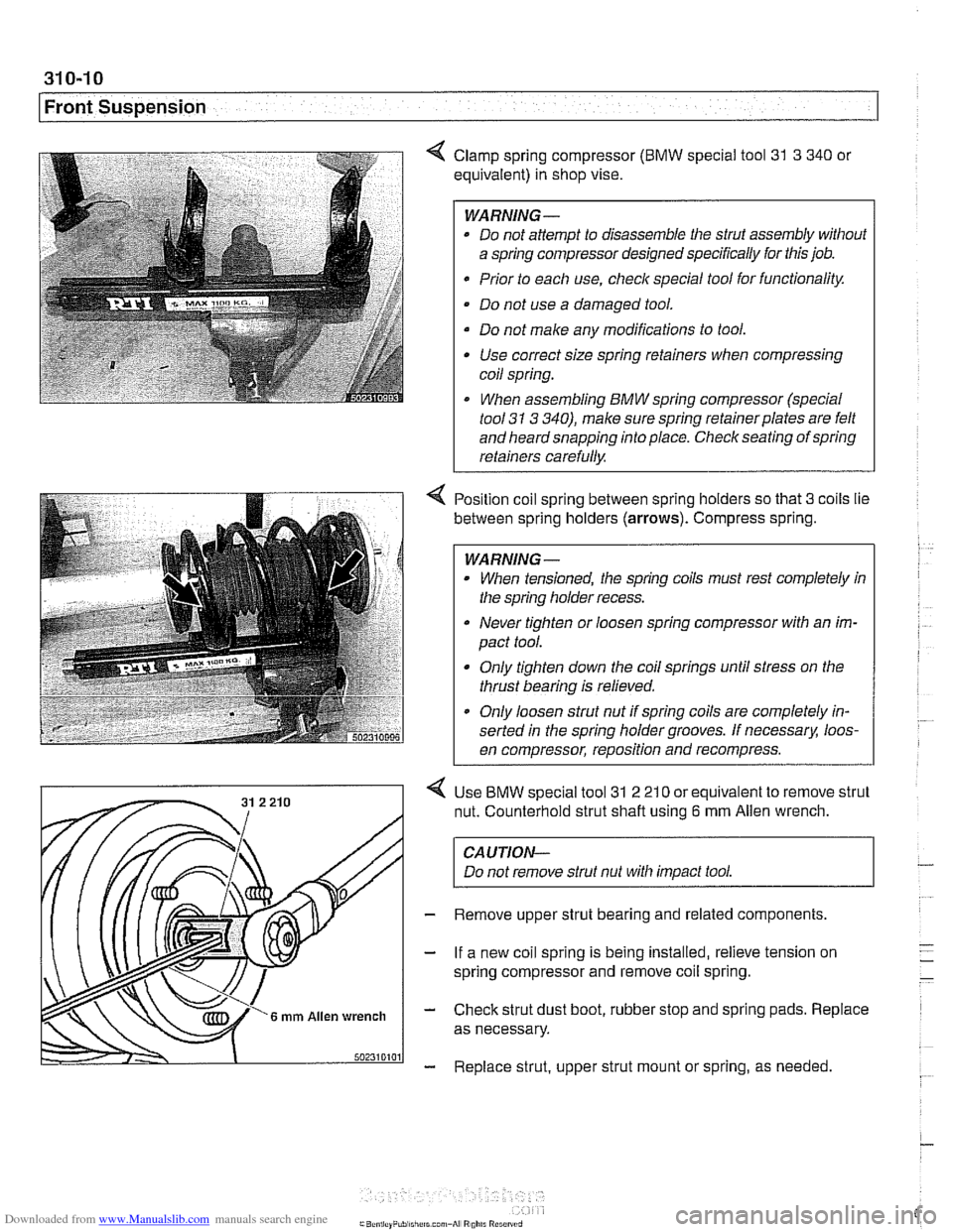
4 Clamp spring compressor (BMW special tool 31 3 340 or
equivalent) in shop vise.
WARNING-
* Do not attempt to disassemble the strut assembly without
a spring compressor designed specifically for this job.
Prior to each use,
checlc special tool for functionality.
Do not use a damaged tool.
Do not make any modifications to tool. Use correct size spring retainers when compressing
coil spring.
I When assembling BMW spring compressor (special
tool
31 3 340), make sure spring retainerplates are felt
and heard snapping into place. Check seating of spring
retainers carefully.
Position coil spring between spring holders so that
3 coils lie
between spring holders
(arrows). Compress spring.
WARNING -
When tensioned, the spring coils must rest completely in
the spring holder recess.
Never tighten or loosen spring compressor with an im-
pact tool.
Only tighten down the coil springs until stress on the
thrust bearing is relieved.
a Only loosen strut nut if spring coils are completely in-
serted in the spring holder grooves. If
necessarx loos-
en compressor, reposition and recompress.
Use
BMW special tool 31 2 21 0 or equivalent to remove strut
nut. Counterhold strut shaft using
6 mm Allen wrench.
CAUTION-
Do not remove strut nut with impact tool.
Remove upper strut bearing and related components.
If a new coil spring is being installed, relieve tension on
spring compressor and remove coil spring.
Check strut dust boot, rubber stop and spring pads. Replace
as necessary.
Replace strut, upper strut mount or spring, as needed