automatic transmission BMW 528i 1997 E39 User Guide
[x] Cancel search | Manufacturer: BMW, Model Year: 1997, Model line: 528i, Model: BMW 528i 1997 E39Pages: 1002
Page 322 of 1002
Downloaded from www.Manualslib.com manuals search engine
11 9-2
Lubrication System
This repair group covers lubrication system troubleshooting
as well as oil pan removal and oil pump replacement.
In 6-cylinder models, removal of the oil pan requires the re-
moval of the exhaust system and some front suspension
components. Those procedures are fully covered in:
180 Exhaust System
210 Clutch
230 Manual Transmission
0 240 Automatic Transmission
310 Front Suspension
320 Steering and Wheel Alignment
NOTE-
Oil change procedure and oil filter replacement are covered
in
020 Maintenance.
CAUTIOG
V8 engines: The oil pump fasteners (including the sprocket
retaining nut) are known to vibrate loose. This can result in oil
starvation and engine failure. Be sure to check oil bolts and
nut tightness whenever the
oilpump is accessible. If any fas-
teners are found to be loose, remove them and reinstall with
Loctite
Band torque to specifications.
Special tools
The engine needs to be properly supported while the front
suspension
subframe is lowered to access the oil pan.
A standard oil pressure gauge may be used for measuring oil
pressure.
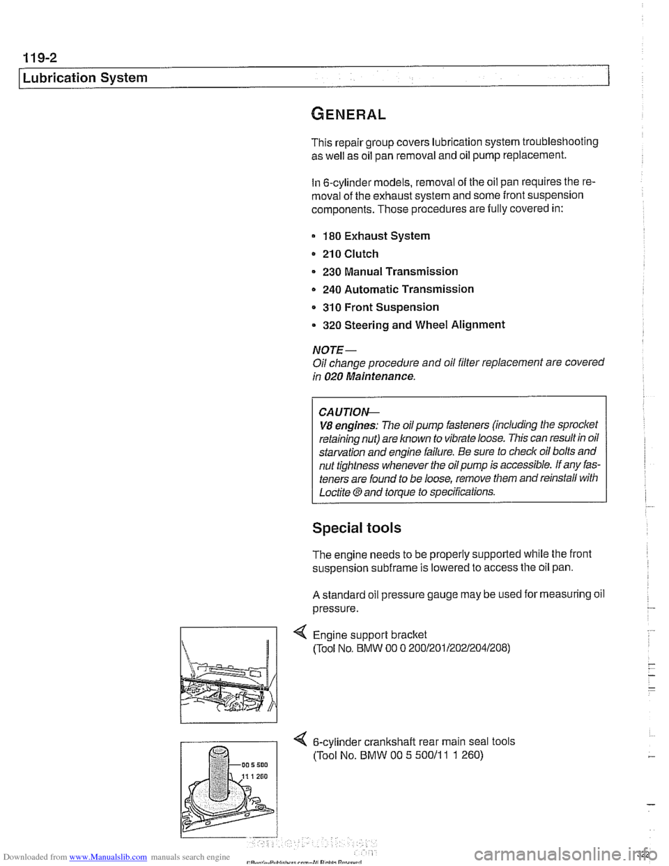
Engine support bracket
(Tool No, BMW 00 0 20012011202~2041208)
4 6-cylinder crankshalt rear main seal tools
(Tool No. BMW 00 5 50011
1 1 260)
Page 326 of 1002
Downloaded from www.Manualslib.com manuals search engine
Lubrication System
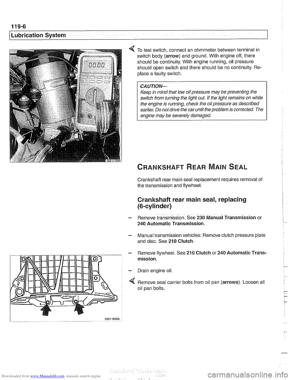
To test switch, connect an ohmmeter between terminal in
switch body (arrow) and ground. With engine off, there
should be continuity. With engine running, oil pressure
should open switch and there should be no continuity. Re-
place a faulty switch.
CAUTION-
Keep in mind that low oil pressure may be preventing the
switch from turning the light out
If the light remains on while
the engine is running, check the oil pressure as described
earlier. Do not drive the car until the problem is corrected. The
engine may be severely damaged.
Crankshaft rear main seal replacement requires removal of
the transmission and flywheel.
Crankshaft rear main seal, replacing
(&cylinder)
- Remove transmission. See 230 Manual Transmission or
240 Automatic Transmission.
- Manual transmission vehicles: Remove clutch pressure plate
and disc. See
210 Clutch.
- Remove flywheel. See 210 Clutch or 240 Automatic Trans-
mission.
- Drain engine oil.
4 Remove seal carrier bolts from oil pan (arrows). Loosen all
oil pan bolts.
Page 328 of 1002
Downloaded from www.Manualslib.com manuals search engine
I Lubrication System -
- Remainder of assembly is reverse of disassembly.
Install flywheel, clutch or torque converter and
transmission.
Fill engine with oil.
- Run engine and check for leaks.
Tightening torques
Oil
drain plug fo oil pan (MI21 25 Nm (18 ft-lb)
Oil pan to engine
block
M6 (8.8 grade) 10 Nm (89 in-ib)
M6 (1 0.9 grade) 12 Nm (9 ft-lb)
M8 (8.8 grade) 22 Nm (1 6 it-lb)
Rear main seal carrier to crankcase
M6 10 Nm (89 in-lb)
ME 22 Nm (16 ft-lb)
Crankshaft rear main seal, replacing (V-8)
- Remove transmission. See 230 Manual Transmission or
240 Automatic Transmission.
- Manual transmission vehicles: Remove clutch pressure plate
and disc. See
210 Clutch.
- Remove flywheel. See 210 Clutch.
- Drain engine oil.
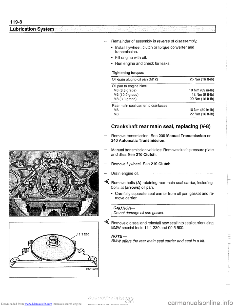
4 Remove bolts (A) retaining rear main seal carrier, including
bolts at (arrows) oil pan.
Carefully separate seal carrier from oil pan gasket and re-
move carrier.
CAUTION-
Do not damage oil pan gasket.
< Remove old seal and reinstall new seal into seal carrier using
) BMW special tools 11 1 230 and 00 5 500.
Page 331 of 1002
Downloaded from www.Manualslib.com manuals search engine
Lubrication system/
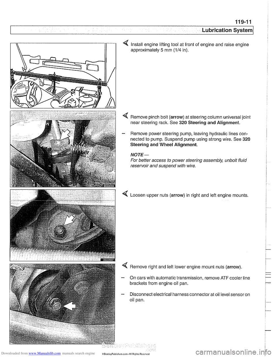
4 Install engine lifting tool at front of engine and raise engine
approximately
5 mm (114 in).
< Remove pinch bolt (arrow) at steering column universal joint
near steering rack. See
320 Steering and Alignment.
- Remove power steering pump, leaving hydraulic lines con-
nected to pump. Suspend pump using strong wire. See
320
Steering and Wheel Alignment.
NOTE-
For better access to power steering assembly, unbolt fluid
reservoir and suspend with wire.
Loosen upper nuts (arrow) in right and lefl engine mounts,
< Remove right and left lower engine mount nuts (arrow)
- On cars with automatic transmission, remove ATF cooler line
brackets from engine oil pan.
- Disconnect electrical harness connector at oil level sensor on
oil pan.
Page 333 of 1002
![BMW 528i 1997 E39 User Guide Downloaded from www.Manualslib.com manuals search engine
-- . - .. . - Lubrication system]
- Remainder of installation is reverse of removal.
Replace self-locking nuts when reinstalling front BMW 528i 1997 E39 User Guide Downloaded from www.Manualslib.com manuals search engine
-- . - .. . - Lubrication system]
- Remainder of installation is reverse of removal.
Replace self-locking nuts when reinstalling front](/img/1/2822/w960_2822-332.png)
Downloaded from www.Manualslib.com manuals search engine
-- . - .. . - Lubrication system]
- Remainder of installation is reverse of removal.
Replace self-locking nuts when reinstalling front suspen-
sion components.
Use new oil dipstick tube sealing O-ring.
After adding engine oil, start and run engine. Raise engine
speed to 2,500 rpm until oil pressure warning light goes out
(about 5 seconds).
NOTE-
BMW does not specify a front end alignment following this
procedure.
Tightening torques Front subfrarne to body rail
(M12, use new bolts)
8.8 grade
10.9 grade
12.9 grade 77 Nrn
(57 ft-lb)
105 Nrn (77 ft-lb)
110 Nrn (81 ft-lb)
Stabilizer bar link to stabilizer bar
65 Nrn (48 ft-lb)
Steering shaft universal joint clamping bolt
(use new bolt)
19 Nrn (14 it-lb)
Lower oil pan, removing and installing (V-8)
- The V-8 engine is equipped with a 2-piece oil pan. The fas-
teners in
V-8 engine oil pump assembly, including the
sprocket retaining nut, are known to loosen and fall off into
the oil pan. Be sure to install these fasteners with Loctite
O
or equivalent thread locking product and torque to specifica-
tions.
CAUTION-
It is recommended that the oil pump retaining bolts and oil
pump drive sprocket retaining nut tightening torque be
checkedany time the
oilpan is removed.
- Raise car and place securely on jack stands.
WARNING-
Make sure the car is stable and well supported at all times.
Use a professional automotive lift
orjack stands designed for
- Remove splash shield from under engine.
- Drain engine oil
- On cars with automatic transmission, remove ATF cooler line
brackets from oil pan.
Page 374 of 1002
Downloaded from www.Manualslib.com manuals search engine
121-8
/Battery, Starter, Alternator
NOTE-
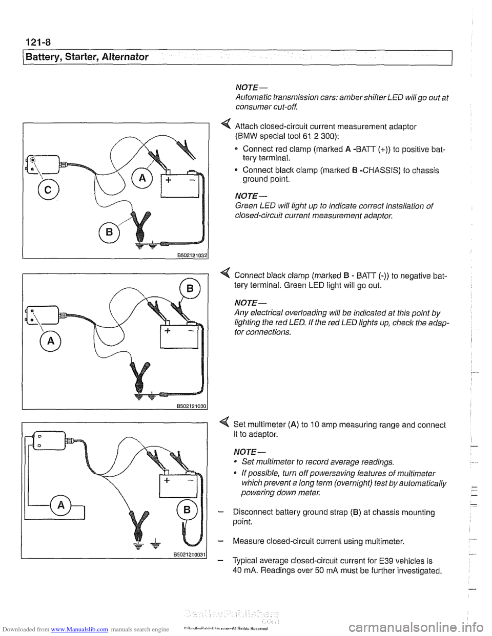
Automatic transmission cars: ambershifier LED willgo out at
consumer cut-off.
4 Attach closed-circuit current measurement adaptor
(BMW special tool
61 2 300):
Connect red clamp (marked A -BATT (+)) to positive bat-
tery terminal.
Connect
black clamp (marked B -CHASSIS) to chassis
ground point.
NOTE-
Green LED will light up to indicate correct installation of
closed-circuit current measurement
adaotor.
< Connect blaclc clamp (marked B - BATT (-)) to negative bat-
tery terminal. Green
LED light will go out.
NOTE-
Any electrical overloading will be indicated at this point by
lighting the red
LED. If the red LED lights up, check the adap-
tor connections.
< Set multimeter (A) to 10 amp measuring range and connect
it to adaptor.
NOTE -
Set multimeter to record average readings.
Ifpossible, turn offpowersaving features of multimeter
which prevent a long term (overnight) test by automatically
powering down
meter.
- Disconnect battery ground strap (B) at chassis mounting
point.
- Measure closed-circuit current using multimeter.
- Typical average closed-circuit current for E39 vehicles is
40 mA. Readings over 50 mA must be further investigated.
Page 385 of 1002
Downloaded from www.Manualslib.com manuals search engine
Battery, Starter, Alternator
- Installation is reverse of removal, noting the following:
Replace alternator rubber sealing O-ring.
* Fill and bleed cooling system as described in 170 Radiator
and Cooling System.
Tightening torques
Fan clutch to coolant pump
with
BMW special tool 11 5 040 30 Nm (22 ft-lb)
without
BMW special tool 11 5 040 40 Nm (29 ft-lb)
Terminal 30 (Bc) wire to alternator (ME) 13 Nm (10 ft-lb)
STARTER
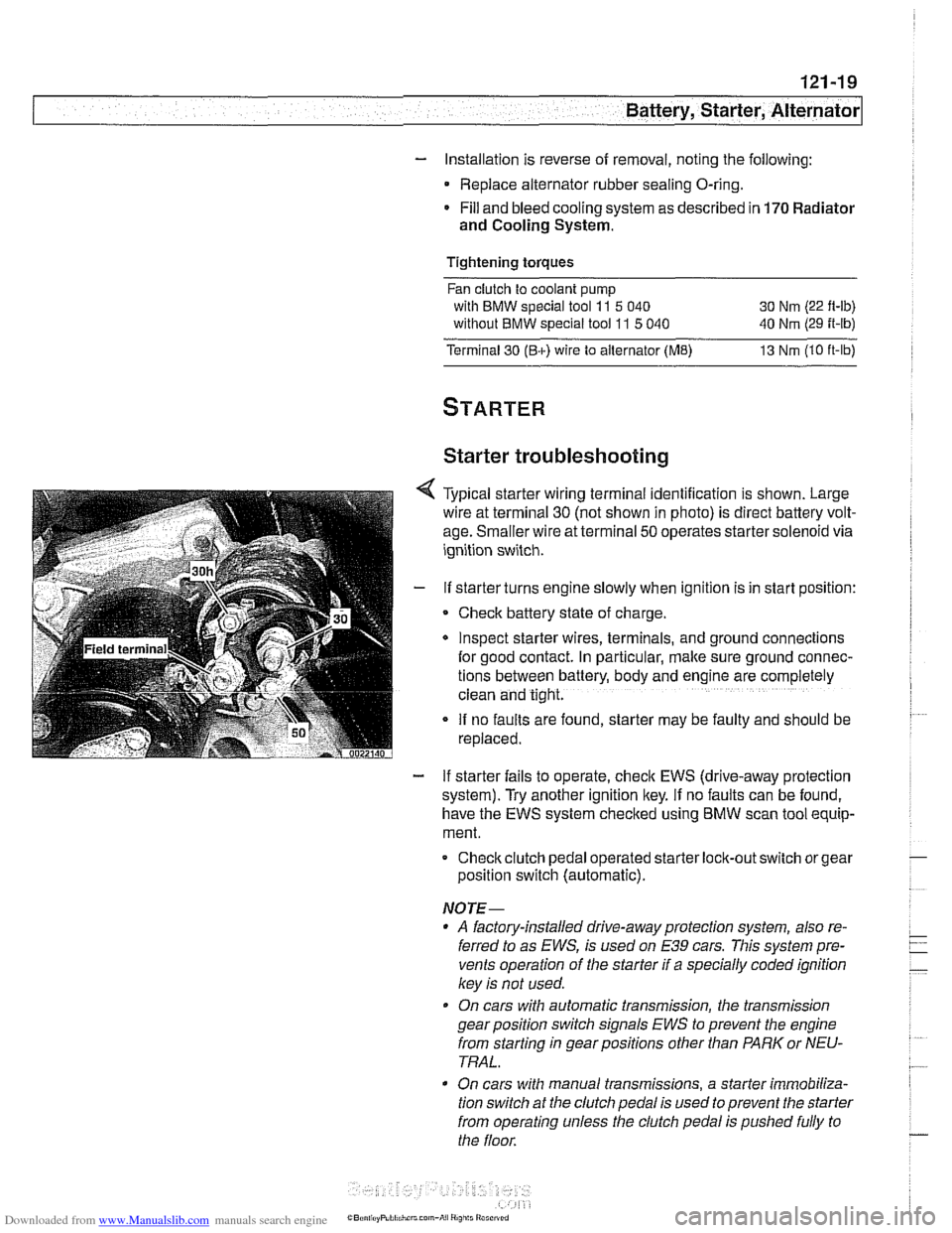
Starter troubleshooting
Typical starter wiring terminal identification is shown. Large
wire at terminal
30 (not shown in photo) is direct battery volt-
age. Smaller wire at terminal
50 operates starter solenoid via
ignition switch.
If starter turns engine slowly when ignition is in start position:
Check battery state of charge.
Inspect starter wires, terminals, and ground
connectlons
for good contact. In particular, make sure ground connec-
tions between battery, body and
englne are completely
clean and tight.
If no faults are found, starter may be faulty and should be
replaced.
- If starter fails to operate, check EWS (drive-away protection
system). Try another ignition key.
If no faults can be found,
have the EWS system checked using
BMW scan tool equip-
ment.
Checkclutch pedal operated
starter lock-out switch or gear
position switch (automatic).
NOTE-
* A factory-installed drive-away protection system, also re-
ferred to as
EWS, is used on E39 cars. This system pre-
vents operation of the starter if a specially coded ignition
key is not used.
On cars with automatic transmission, the transmission
gear position switch signals
EWS to prevent the engine
from starting in gear positions other than PARK or NEU-
TRAL.
On cars with manual transmissions, a starter immobiliza-
tion switch
at the clutch pedal is used to prevent the starter
from operating unless the clutch pedal is pushed fully to
the floor.
Page 412 of 1002
Downloaded from www.Manualslib.com manuals search engine
/Fuel injection
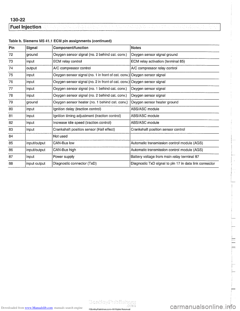
Table b. Siemens MS 41.1 ECM pin assignments (continued)
85
86
87
88 CAN-Bus low
CAN-Bus high
Power supply
Diagnostic connector
(TxD)
inputloutput
inpuWoutput
input
input output Automatic transmission control module (AGS)
Automatic transmission control module (AGS)
Battery voltage from main relay terminal 87
Diagnostic TxD signal to pin 17 in data link connector
Page 466 of 1002
Downloaded from www.Manualslib.com manuals search engine
130-76
Fuel Injection
Bosch
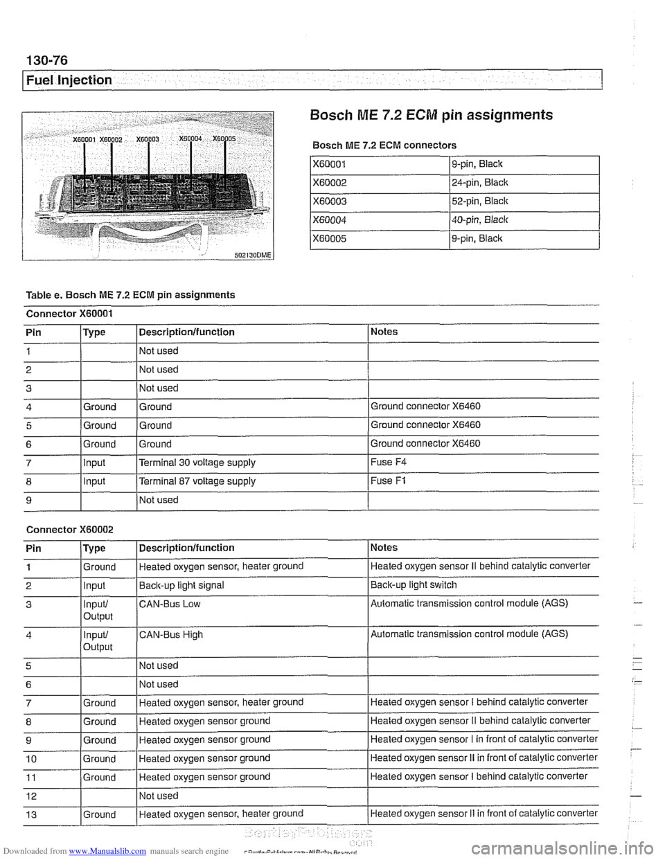
ME 7.2 ECM pin assignments
Bosch ME 7.2 ECM connectors
X60001
X60002
X60003
X60004
X60005
Table e. Bosch ME 7.2 ECM pin assignments
Connector
X60001
I I I
8 1 lnput [Terminal 87 voltage supply I Fuse F1
9-pin, Black
24-pin, Black
52-pin, Black
40-pin, Black
9-pin,
Blaclc
I I I
9 I NO^ used I
Notes
Ground connector
X6460
Ground connector X6460
Pin 1
2 3
4
5
Connector X60002
Ground connector X6460 6
Pin
/Type I Descriptionlfunction 1 Notes
Type
Ground
Ground
7 llnput l~errninai 30 voltage supply I Fuse F4
Descriptionlfunction
Not used
Not used
Not used
Ground Ground
Ground Ground
1
2
3
4
5
6
7
8
9
10
11
12
13
. . - Ground Input
Input/
output
input/
Output
Ground
Ground
Ground
Ground
Ground
Ground Heated oxygen sensor, heater ground
Back-up
light signal
CAN-BUS Low
CAN-Bus High
Not used Not used
Heated oxygen sensor, heater ground
Heated oxygen sensor ground
Heated oxygen sensor ground
Heated oxygen sensor ground
Heated oxygen sensor ground
Not used
Heated oxvaen sensor, heater
ground
Heated oxygen sensor II behind catalylic converter
Baclcup light switch
Automatic transmission control module (AGS)
Automatic transmission control module (AGS)
Heated oxygen sensor
I behind catalytic converter
Heated oxygen sensor
II behind catalytic converter
Heated oxygen sensor I in front of catalytic converter
Heated oxygen sensor
II in front of catalytic converter
Heated oxygen sensor
I behind catalytic converter
Heated oxygen sensor
Ii in front of catalytic converter
Page 500 of 1002
Downloaded from www.Manualslib.com manuals search engine
-
I Radiator and Cooling System
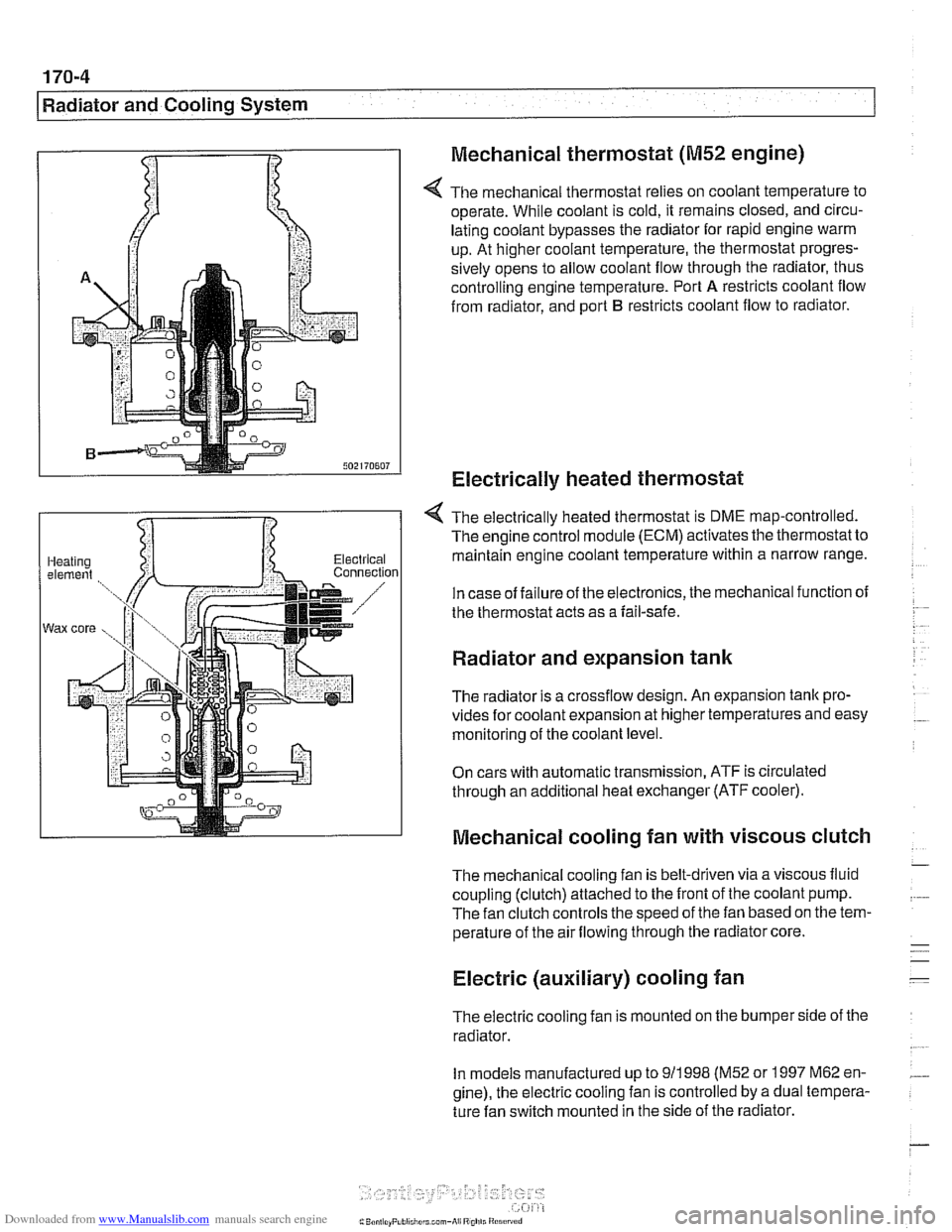
Mechanical thermostat
(M52 engine)
4 The mechanical thermostat relies on coolant temperature to
operate. While coolant is cold, it remains closed, and circu-
lating coolant bypasses the radiator for rapid engine warm
up. At higher coolant temperature, the thermostat progres-
sively opens to allow coolant flow through the radiator, thus
controlling engine temperature. Port
A restricts coolant flow
from radiator, and port
B restricts coolant flow to radiator.
Electrically heated thermostat
4 The electrically heated thermostat is DME map-controlled.
The engine control module (ECM) activates the thermostat to
maintain engine coolant temperature within a narrow range.
In case of failure of the electronics, the mechanical function of
the thermostat acts as a fail-safe.
Radiator and expansion tank
The radiator is a crossflow design. An expansion tank pro-
vides for coolant expansion at higher temperatures and easy
monitoring of the coolant level.
On cars with automatic transmission, ATF is circulated
through an additional heat exchanger (ATF cooler).
Mechanical cooling fan with viscous clutch
The mechanical cooling fan is belt-driven via a viscous fluid
coupling (clutch) attached to the front of the coolant pump.
The fan clutch controls the speed of the fan based on the tem-
perature of the air flowing through the radiator core.
Electric (auxiliary) cooling fan
The electric cooling fan is mounted on the bumper side of the
radiator.
In models manufactured up to
911 998 (M52 or 1997 M62 en-
gine), the electric cooling fan is controlled by a dual tempera-
ture fan switch mounted in the side of the radiator.