automatic transmission BMW 528i 1997 E39 Service Manual
[x] Cancel search | Manufacturer: BMW, Model Year: 1997, Model line: 528i, Model: BMW 528i 1997 E39Pages: 1002
Page 604 of 1002
Downloaded from www.Manualslib.com manuals search engine
pearshift Linkage
~UTOMATIC TRANSMISSION
GEARSHIFT
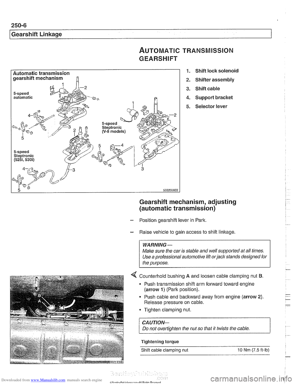
Automatic transmission gearshift mechanism
automatic
5-speed Steptronic (5251,530i)
1. Shift lock solenoid
2. Shifter assembly
3. Shift cable
4. Support bracket
5. Selector lever
Gearshift mechanism, adjusting
(automatic transmission)
- Position gearshift lever in Park.
- Raise vehicle to gain access to shift linkage.
WARNING -
Make sure the car is stable and well supported at all times.
Use a professional automotive
lift orjack stands designed for
the purpose.
4 Counterhold bushino A and loosen cable clam~ino nut 6.
Push cable end backward away from engine (arrow 2).
Release pressure on cable.
Tighten clamping nut.
/ CAUTION--
Tightening torque
Shift cable clamping nut
10 Nm (7.5 it-lb)
Page 605 of 1002
Downloaded from www.Manualslib.com manuals search engine
250-7
Gearshift ~inka~el
Automatic shiftlock, checking function (automatic transmission)
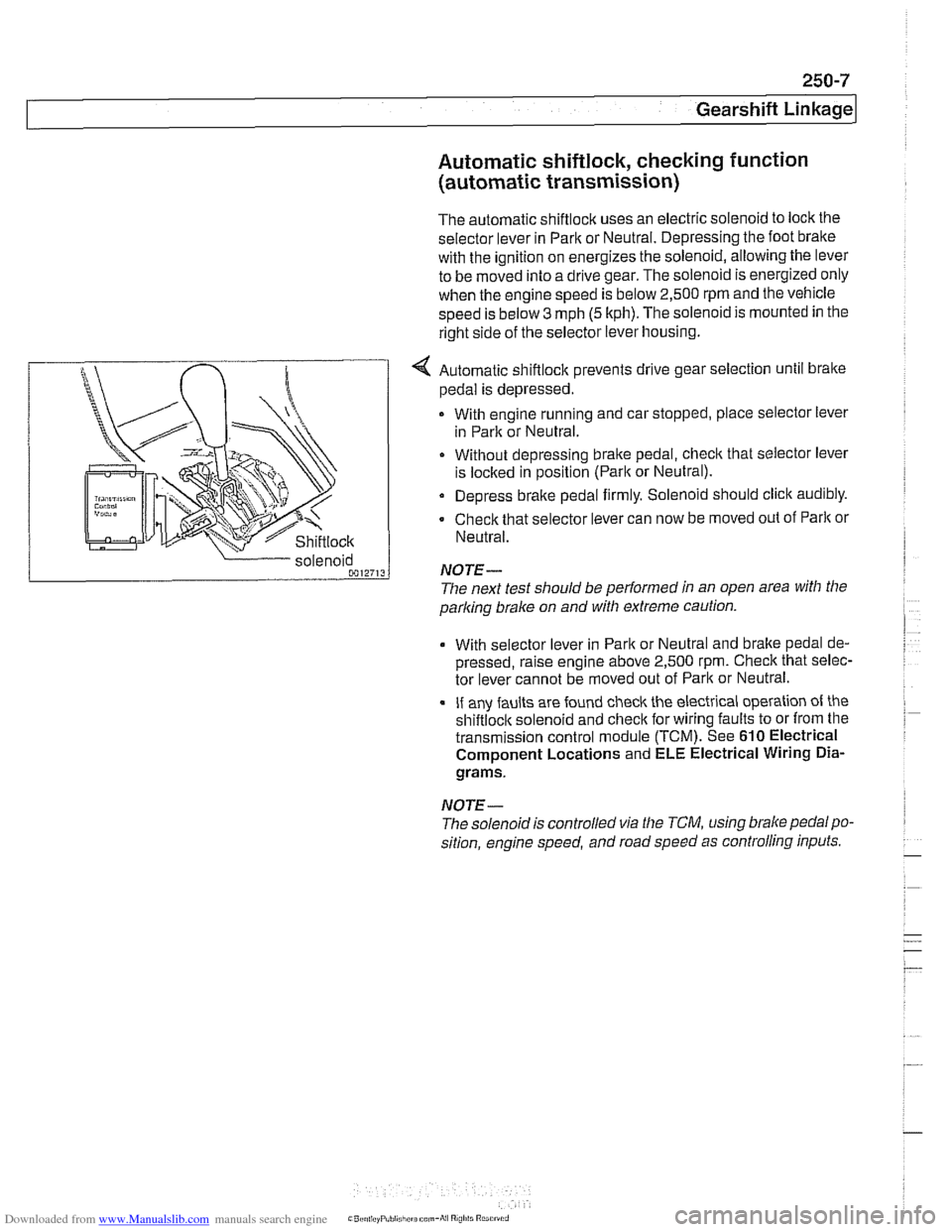
The automatic shiftlock uses an electric solenoid to lock the
selector lever in Park or Neutral. Depressing the foot bralte
with the ignition on energizes the solenoid, allowing the lever
to be moved into a drive gear. The solenoid is energized only
when the engine speed is below 2,500 rpm and the vehicle
speed is below
3 mph (5 kph). The solenoid is mounted in the
right side of the selector lever housing.
... nir r
Shiftlock
4 Automatic shiftlock prevents drive gear selection until brake
pedal is depressed.
With engine running and car stopped, place selector lever
in Park or Neutral.
Without depressing bralte pedal, check that selector lever
is
loclted in position (Parlt or Neutral).
Depress brake pedal firmly. Solenoid should click audibly.
Check that selector lever can now be moved out of
Parlt or
Neutral.
parking
brake on and with extreme caution.
solenoid
0012713
With selector
lever in Park or Neutral and bralte pedal de-
pressed, raise engine above 2,500
rpm. Check that selec-
tor lever cannot be moved out of Park or Neutral.
If any faults are found check the electrical operation of the
shiftloclt solenoid and checlt for wiring faults to or from the
transmission control module (TCM). See
610 Electrical
Component Locations and ELE Electrical Wiring
Dia-
grams.
NOTE-
NOTE-
The solenoidis controlled via the TCM, using brake pedalpo-
sition, engine speed, and road speed as controlling inputs.
The
next test should be performed in an open area with the
Page 606 of 1002
Downloaded from www.Manualslib.com manuals search engine
250-8
Gearshift Linkage
-;Ag Gate "",?it.,
Shift interlock, checking function
(automatic transmission)
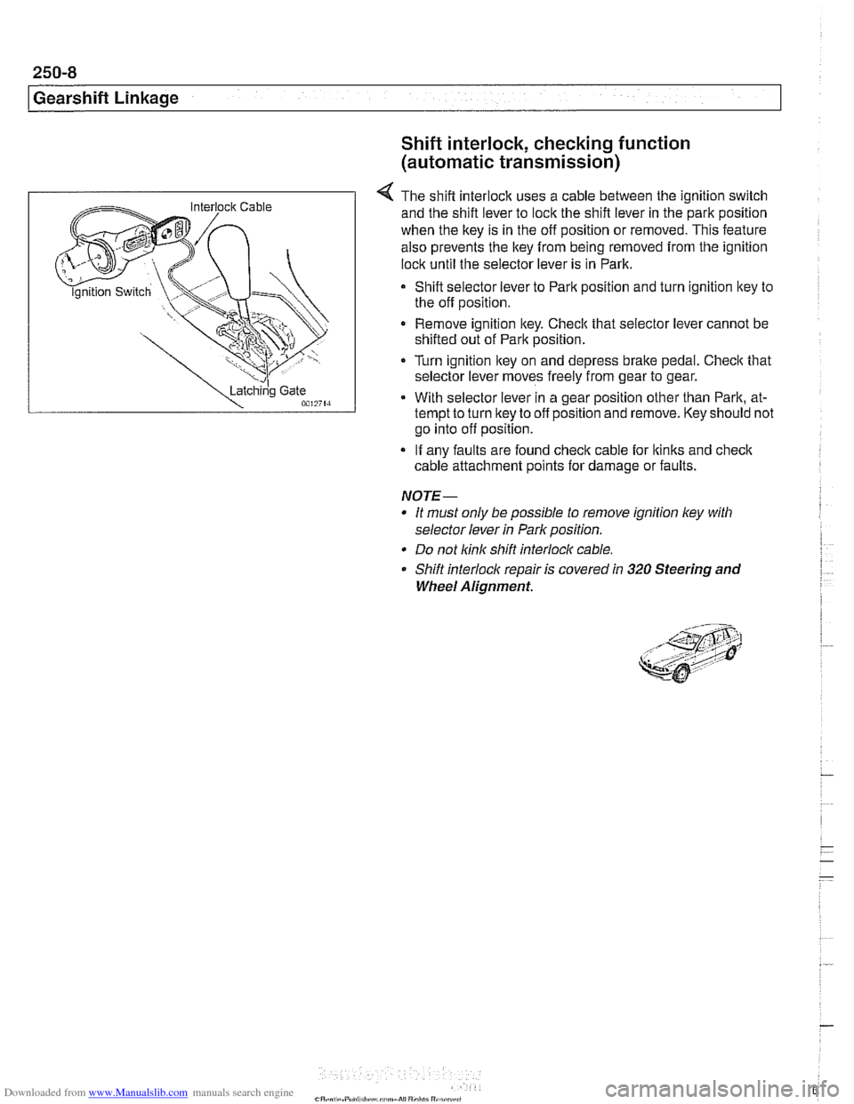
4 The shift interlock uses a cable between the ignition switch
and the shift lever to lock the shift lever in the park position
when the key is in the off position or removed. This feature
also prevents the key
from being removed from the ignition
lock until the selector lever is in Park.
Shift selector lever to Park position and turn ignition key to
the off position.
Remove ignition key. Checlc that selector lever cannot be
shifted out of Park position.
Turn ignition lkey on and depress
brake pedal. Checlc that
selector lever moves freely from gear to gear.
With selector lever in a gear position other than Park, at-
tempt to turn lkey to off position and remove. Key should not
go into off position.
If any faults are found check cable for lkinks and
check
cable attachment points for damage or faults.
NOTE-
* It must only be possible to remove ignition ley with
selector lever
in Park position.
* Do not link shift interlocl( cable.
Shift interlock repair is covered
in 320 Steering and
Wheel Alignment.
Page 631 of 1002
Downloaded from www.Manualslib.com manuals search engine
Suspension, Steering and Brakes - General
WHEELS AND TIRES
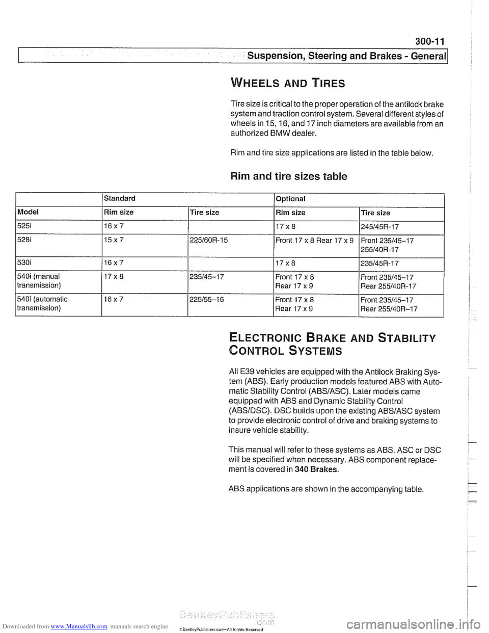
Tire size is critical to the properoperation of the antilock brake
system and traction control system. Several differentstyles of
wheels in
15,16, and 17 inch diameters are available from an
authorized BMW dealer.
Rim and tire size applications are listed in the table below.
Rim and tire sizes table
ELECTRONIC BRAKE AND STABILITY
CONTROL SYSTEMS
Model
5251
5281
530i
540i (manual
transmission)
540i (automatic
transmission)
All
E39 vehicles are equipped with the Antilock Braking Sys-
tem
(ABS). Early production models featured ABS with Auto-
matic Stability
control (ABSIASC). Later models came
equipped with ABS and Dynamic Stability Control
(ABSIDSC). DSC builds upon the existing ABSIASC system
to provide electronic control of drive and braking systems to
insure vehicle stability.
This manual will refer to these systems as ABS. ASC or DSC
will be specified when necessary. ABS component replace-
ment is covered in
340 Brakes.
Standard
ABS applications are shown in the accompanying table
Rim size
16x7
15x7
16x7
17x8
16x7 Optional
Tire size
225160R-15
235145-1 7
225155-1 6
Rim size
17x8
Front 17
x 8 Rear 17 x 9
17 x 8
Front 17x8
Rear 17x9
Front 17 x 8
Rear 17 x 9 Tire
size
245145R-17
Front 235145-1 7
255140R-17
235145R-17
Front 235145-1 7
Rear
255140R-17
Front 235145-17
Rear 255140R-17
Page 659 of 1002
Downloaded from www.Manualslib.com manuals search engine
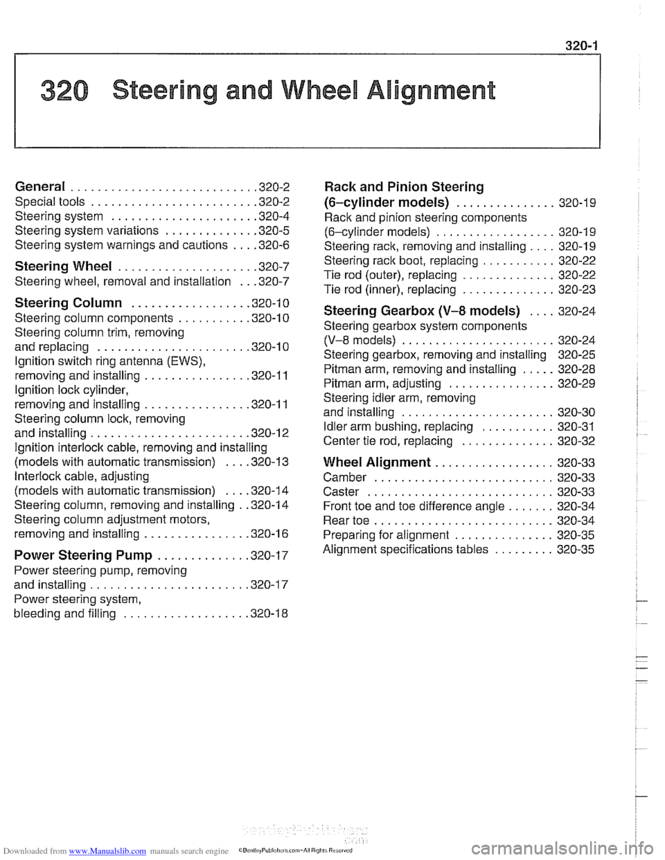
1 320 Steering and Wheel Alignment
General ........................... .32 0.2
Special tools
........................ .32 0.2
Steering system
..................... .32 0.4
Steering system variations
............. .32 0.5
Steering system warnings and cautions
... .32 0.6
Steering Wheel .................... .32 0.7
Steering wheel. removal and installation
.. .32 0.7
Steering Column ................. .32 0.1 0
Steering column components .......... .32 0.10
Steering column trim, removing
and replacing
...................... .32 0.10
lgnition switch ring antenna (EWS).
removing and installing
............... .32 0.1 1
lgnition lock cylinder.
removing and installing
............... .32 0-1 1
Steering column lock. removing
and installing
....................... .32 0.12
lgnition
interloclc cable. removing and installing
(models with automatic transmission)
... .32 0.13
Interlock cable. adjusting
(models with automatic transmission)
... .32 0.14
Steering column. removing and installing
. .32 0.14
Steering column adjustment motors.
removing and installing
............... .32 0.16
Power Steering Pump ............. .32 0.17
Power steering pump. removing
and installing
....................... .32 0.1 7
Power steering system.
bleeding and filling
.................. .32 0.18
Rack and Pinion Steering
(6-cylinder models)
............... 320-19
Rack and pinion steering components
(6-cylinder models)
.................. 320-1 9
Steering rack. removing and installing
.... 320-19
Steering
rack boot. replacing ........... 320-22
Tie rod (outer). replacing
.............. 320-22
Tie rod (inner). replacing
.............. 320-23
Steering Gearbox (V-8 models) .... 320-24
Steering gearbox system components
. .
(V-8 models) ....................... 320-24
Steering gearbox, removing and installing 320-25
Pitman arm. removing and installing ..... 320-28
Pitman arm. adjusting ................ 320-29
Steering idler arm. removing
and installing
....................... 320-30
Idler arm bushing. replacing ........... 320-31
Center tie rod. replacing
.............. 320-32
Wheel Alignment .................. 320-33
Camber
........................... 320-33
Caster
............................ 320-33
Front toe and toe difference angle
....... 320-34
Reartoe ........................... 320-34
Preparing for alignment
............... 320-35
Alignment specifications tables
......... 320-35
Page 670 of 1002
Downloaded from www.Manualslib.com manuals search engine
I Steering and Wheel Alignment
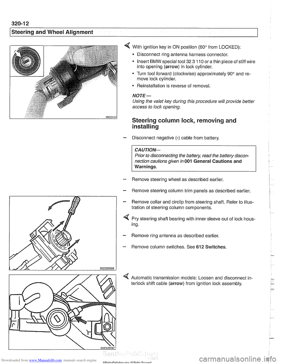
With ignition key in ON position (60" from LOCKED):
- Disconnect ring antenna harness connector.
Insert
BMW special tool 32 3 110 or a thin piece of stiff wire
into opening (arrow) in lock cylinder.
Turn tool forward (clockwise) approximately 90" and re-
move lock cylinder.
* Reinstallation is reverse of removal.
NOTE-
Using the valet ley during this procedure will provide better
access to lock opening.
Steering column lock, removing and
installing
- Disconnect negative (-) cable from battery.
CAUTIO&
Prior to disconnecting the battery, read the battery discon-
nection cautions given
in 001 General Cautions and
Warnings.
- Remove steering wheel as described earlier.
- Remove steering column trim panels as described earlier.
- Remove collar and circlip from steering shaft. Refer to illus-
tration of steering column components.
4 Pry steering shaft bearing with inner sleeve out of lock hous-
ing.
- Remove ring antenna as described earlier.
- Remove column switches. See 612 Switches.
< Automatic transmission models: Loosen and disconnect in-
terloclc shift cable (arrow) from ignition lock assembly.
Page 671 of 1002
Downloaded from www.Manualslib.com manuals search engine
Steering and Wheel Alignment
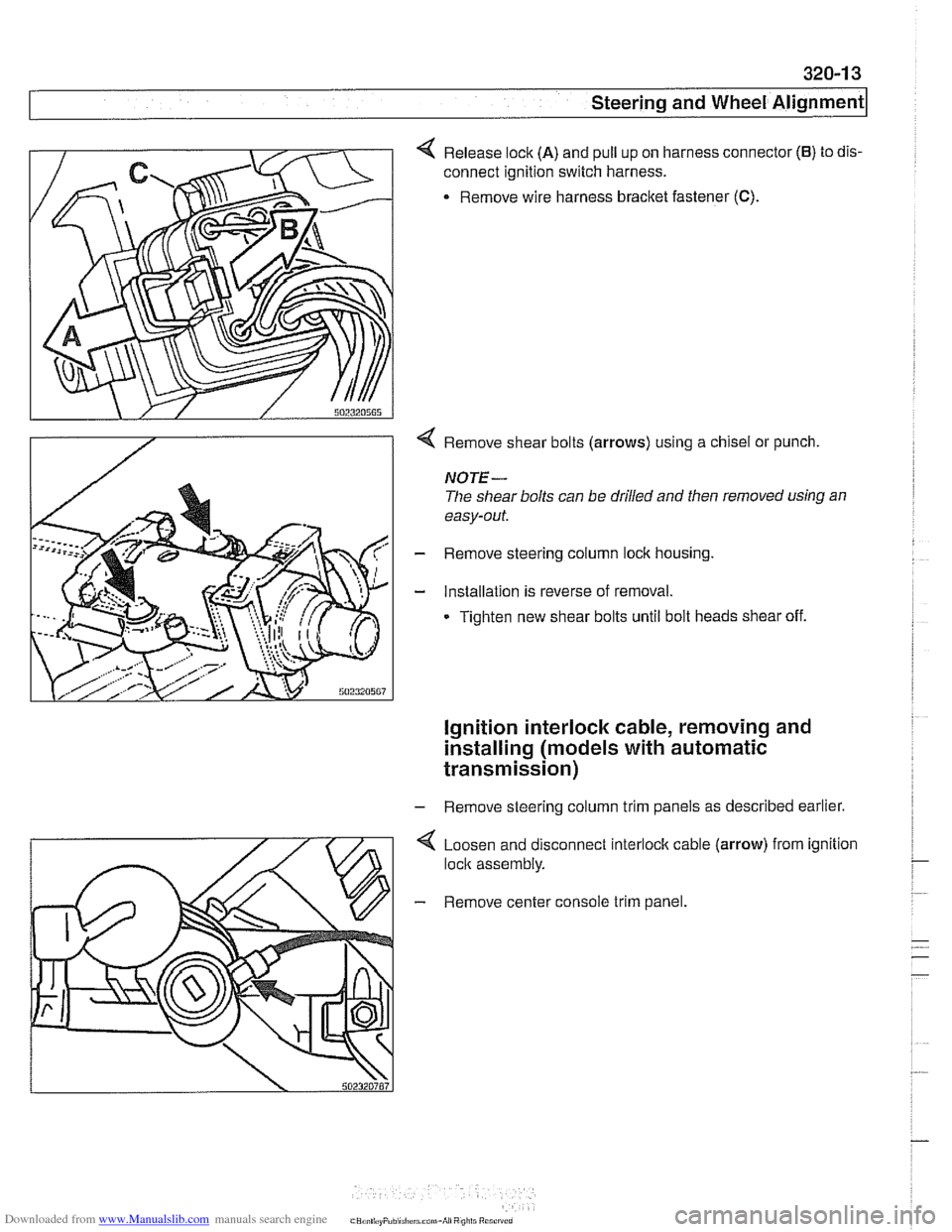
4 Release lock (A) and pull up on harness connector (6) to dis-
connect ignition switch harness.
. Remove wire harness bracket fastener (C).
4 Remove shear bolts (arrows) using a chisel or punch.
NOTE-
The shear bolts can be drilled and then removed using an
easy-out.
- Remove steering column lock housing.
- Installation is reverse of removal.
Tighten new shear bolts until bolt heads shear off.
ignition interlock cable, removing and
installing (models
with automatic
transmission)
- Remove steering column trim panels as described earlier.
4 Loosen and disconnect interlock cable (arrow) from ignition
lock assembly.
- Remove center console trim panel.
Page 672 of 1002
Downloaded from www.Manualslib.com manuals search engine
320-1 4
Steering and Wheel Alignment
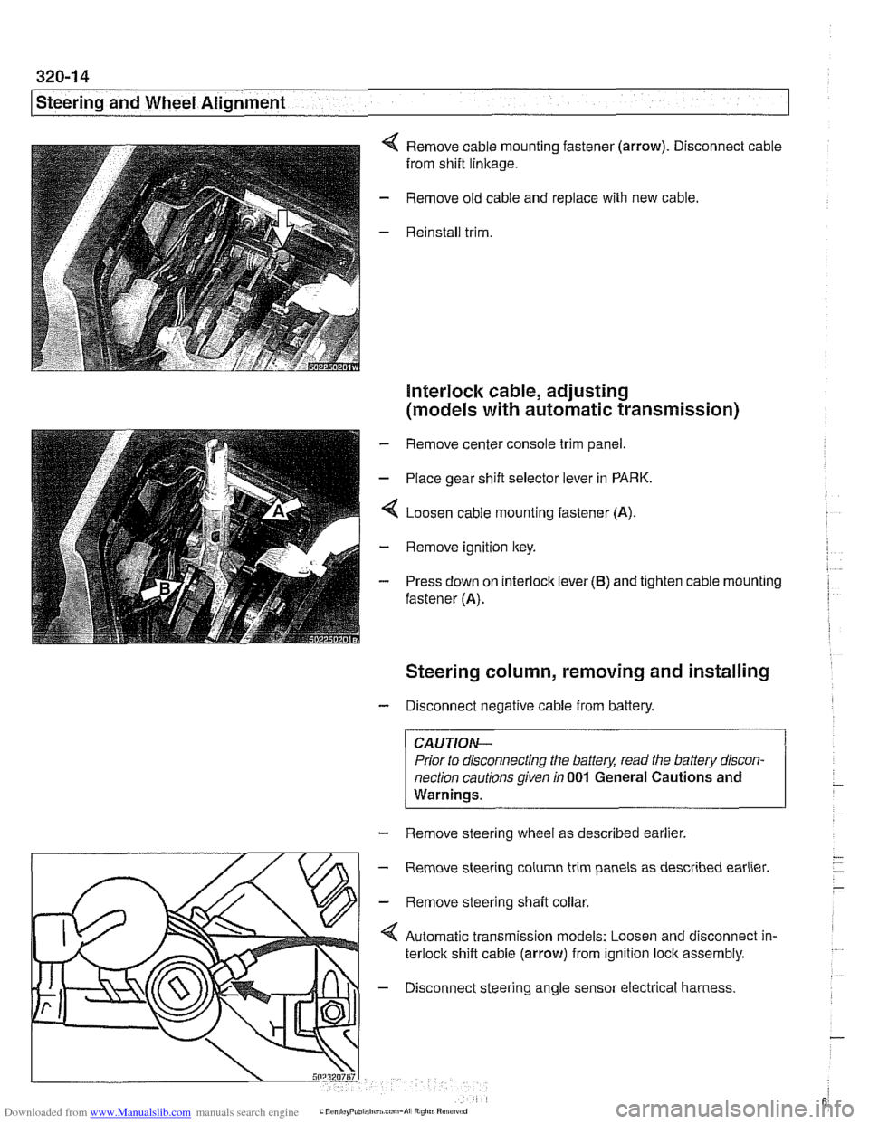
Remove cable mounting fastener (arrow). Disconnect cable
from shift
linkage.
Remove old cable and replace with new cable.
Reinstall trim.
Interlock cable, adjusting
(models with automatic transmission)
- Remove center console trim panel.
- Place gear shift selector lever in PARK.
4 Loosen cable mounting fastener (A).
- Remove ignition key.
- Press down on interlock lever (B) and tighten cable mounting
fastener (A).
Steering column, removing and installing
- Disconnect negative cable from battery.
CAUTIOI\C
Prior to disconnecting the battea read the battery discon-
nection cautions given
in 001 General Cautions and
Warninqs.
- Remove steering wheel as described earlier.
m
- Remove steering column trim panels as described earlier.
' \L/>I - Remove steerinq shaft collar
Automatic transmission models: Loosen and disconnect in-
terlock shift cable (arrow) from ignition lock assembly.
4 - Disconnect steering angle sensor electrical harness.
Page 881 of 1002
Downloaded from www.Manualslib.com manuals search engine
513-3
Interior ~rirnl
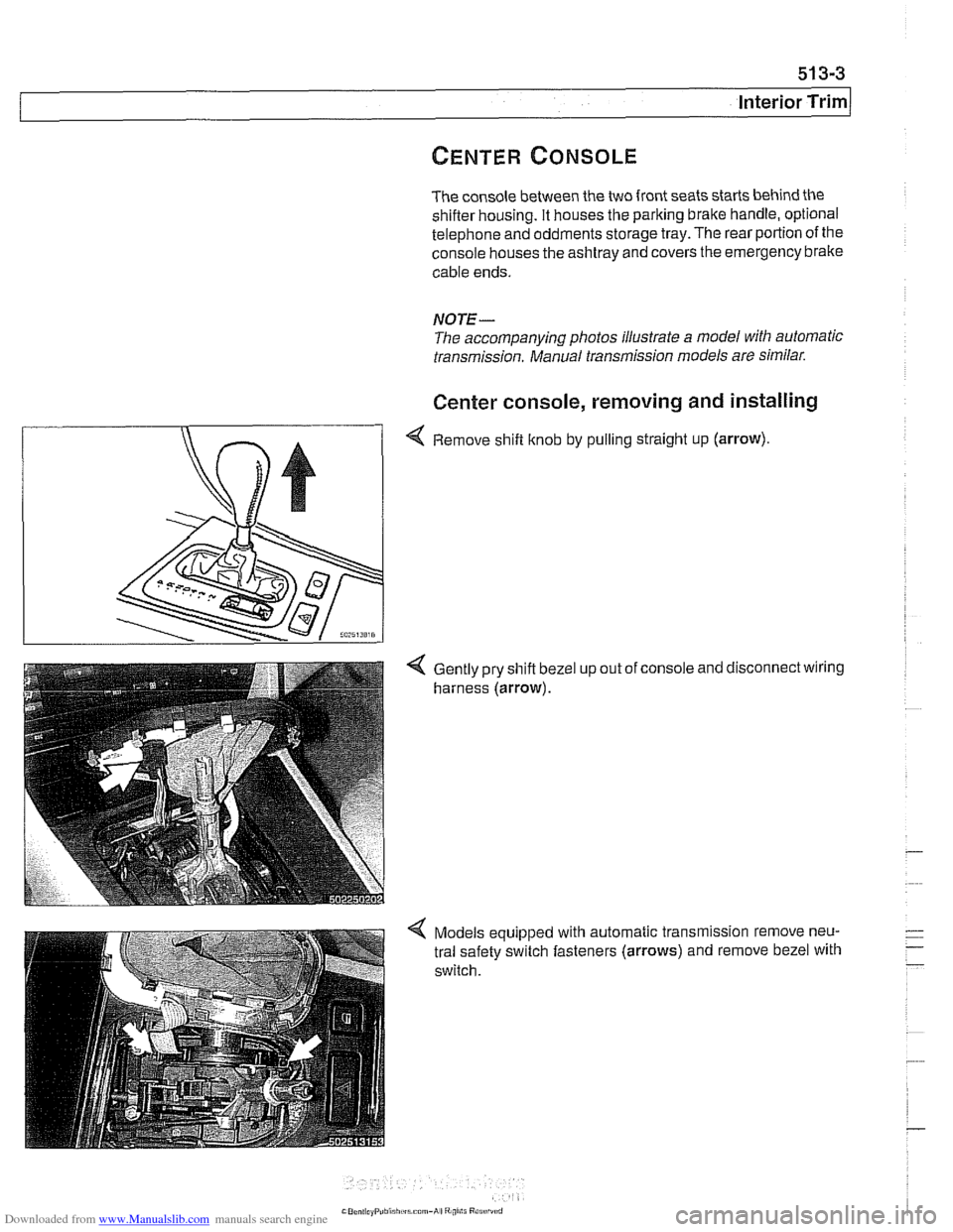
The console between the two front seats starts behind the shifler housing. It houses the parking brake handle, optional
telephone and oddments storage tray. The rear portion of the
console houses the ashtray and covers the emergency brake
cable ends.
NOTE-
The accompanying photos illustrate a model with automatic
transmission. Manual transmission models are similar.
Center console, removing and installing
4 Remove shift knob by pulling straight up (arrow).
Gently pry shift bezel
harness (arrow). up
out of console and disconnect wiring
Models equipped with automatic transmission remove neu-
tral safety switch fasteners (arrows) and remove bezel with
switch.
Page 916 of 1002
Downloaded from www.Manualslib.com manuals search engine
Central Locking and Anii-Theft
- If the starter engages, the following EWS inputs are function-
ing normally:
Ignition key
Code function
Transmission range switch or clutch position switch
Engine speed sensor
NO JE -
If a vehicle key is lost or stolen, the electronic authorization
for that key
can be cancelled using the BMW scan and di-
agnostic tools
DISplus, GTl or MoDiC.
Force applied to a ley can damage the electronic circuitry
in the key A damaged ley will not start the engine. In that
case, a new key should be purchased and initialized
by an
authorized BMW dealer.
EWS variations
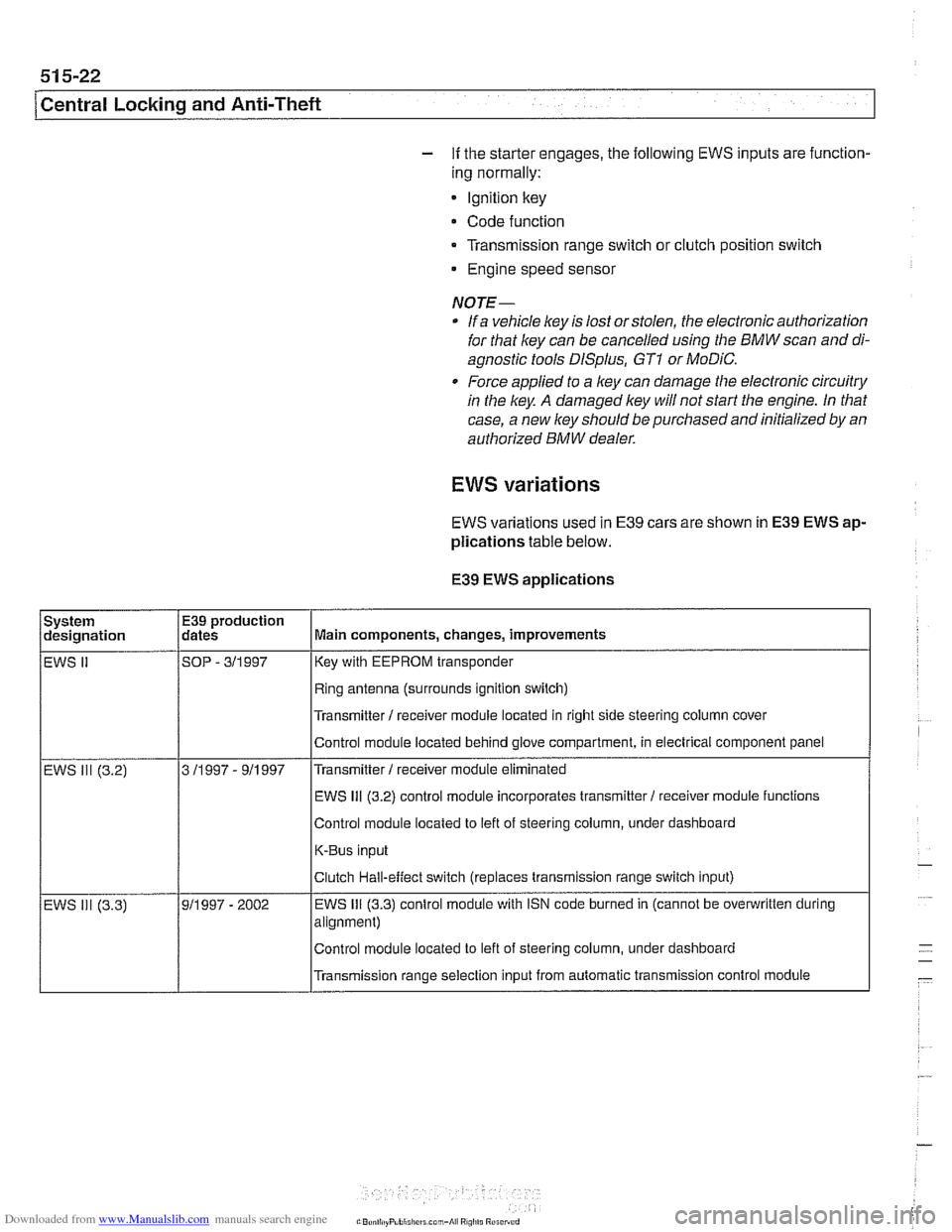
EWS variations used in E39 cars are shown in E39 EWS ap-
plications
table below.
E39
EWS applications
I I Ifling antenna (surrounds ignition switch) I
System
designation
EWS
II
I I l~ransmitter I receiver module located in right side steering column cover I
E39 production
dates
SOP
- 311 997
I I IEWS 111 (3.2) control module incorporates transmitter1 receiver moduie functions /
Main components, changes, improvements
Key with EEPROM transponder
Control moduie located behind glove compartment, in electrical component panel
Control module located to left of steering column, under dashboard
K-Bus input
Transmitter
I receiver module eliminated
EWS 111 (3.2)
Transmission range selection input from automatic transmission control module
3
11997 - 911997
- EWS ill (3.3) Clutch
Hall-effect switch (replaces transmission range switch input)
911997 - 2002 EWS 111 (3.3) control
module with iSN code burned in (cannot be overwritten during
alignment)
Control module located to left of steering column, under dashboard