piston BMW 528i 1997 E39 Owner's Guide
[x] Cancel search | Manufacturer: BMW, Model Year: 1997, Model line: 528i, Model: BMW 528i 1997 E39Pages: 1002
Page 302 of 1002
Downloaded from www.Manualslib.com manuals search engine
11 7-66
I Camshaft Timing Chain
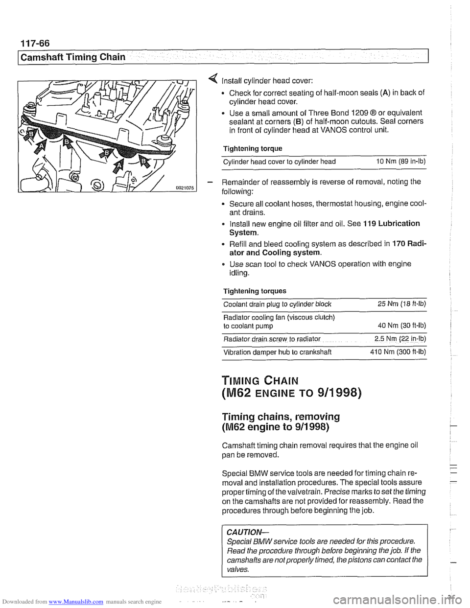
4 install cylinder head cover:
Check for correct seating of half-moon seals
(A) in back of
cylinder head cover.
Use a small amount of Three Bond
1209 8 or equivalent
sealant at corners
(B) of half-moon cutouts. Seal corners
in front of cylinder head at VANOS control unit.
Tightening torque
Cylinder head cover to cylinder head
10 Nm (89 in-lb)
- Remainder of reassembly is reverse of removal, noting the
following:
Secure all coolant hoses, thermostat housing, engine cool-
ant drains.
Install new engine oil filter and oil. See
119 Lubrication
System.
Refill and bleed cooling system as described in
170 Radi-
ator and Cooling system.
Use scan tool to check VANOS operation with engine
idling.
Tightening torques Coolant drain plug to cylinder block
25 Nm (18 ft-lb)
Radiator cooling fan (viscous clutch)
to coolant pump
40 Nm (30 ft-lb)
Radiator drain screw to radrator 2.5 Nm (22 in-lb)
Vibration damper hub to crankshaft 41 0 Nm
(300 ft-ib)
TIMING CHAIN
(M62 ENGINE TO 911998)
Timing chains, removing
(M62 engine to 911 998)
Camshaft timing chain removal requires that the engine oil
pan be removed.
Special
BMW service tools are needed for timing chain re-
moval and installation procedures. The special tools assure
propertiming of thevaivetrain. Precise marks to set the timing
on the camshafts are not provided for reassembly. Read the
procedures through before beginning the job.
CAUTION-
Special BMW service tools are needed for this procedure.
Read the procedure through before beginning the job. If the
camshafts are notproperly timed, the pistons can contact the
valves.
Page 318 of 1002
Downloaded from www.Manualslib.com manuals search engine
[camshaft Timina Chain Cylinders
1-4
11 2445 11 2 441
502116429;
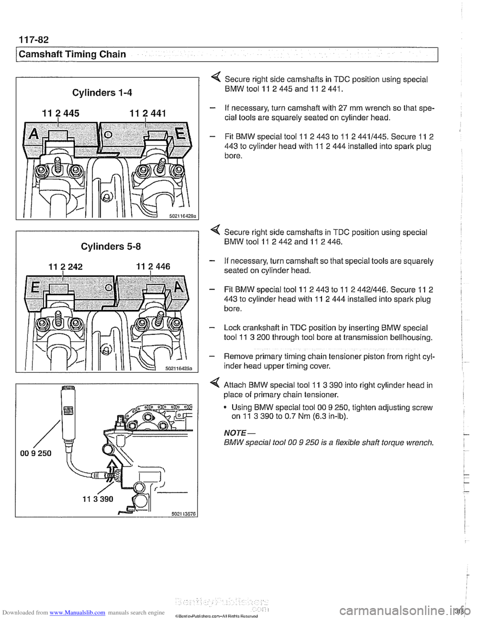
Secure right side camshafts in TDC position using special
BMWtoolll 2445andll 2441.
- If necessary, turn camshaft with 27 mm wrench so that spe-
cial tools are squarely seated on cylinder head.
- Fit BMW special tool 11 2 443 to 11 2 4411445. Secure 11 2
443
to cylinder head with 11 2 444 installed into spark plug
bore.
I
< Secure right side camshafts in TDC position using special
Cylinders 5-8 BMW tool 11 2 442 and 11 2 446.
- If necessary, turn camshaft so that special tools are squarely
seated on cylinder head.
- Fit BMW special tool 11 2 443 to 11 2 4421446. Secure 11 2
443
to cylinder head with 11 2 444 installed into spark plug
bore.
- Lock cranltshaft in TDC position by inserting BMW special
tool
11 3 200 through tool bore at transmission bellhousing.
- Remove primary timing chain tensioner piston from right cyl-
~nder head upper timing cover.
4 Attach BMW special tool 11 3 390 into right cylinder head in
place of primary chain tensioner.
Using BMW special tool
00 9 250, tighten adjusting screw
on
11 3 390 to 0.7 Nm (6.3 in-lb).
NOTE-
BMW special fool 00 9 250 is a flexible shaft torque wrench.
Page 389 of 1002
Downloaded from www.Manualslib.com manuals search engine
121-23
Battery, Starter, ~lternatorl
Solenoid switch, removing and installing
- Remove starter as described previously.
- Disconnect field winding strap between starter motor and
solenoid switch.
NOTE-
If the field winding strap is damaged or burned, a new or
rebuilt starter motor is needed.
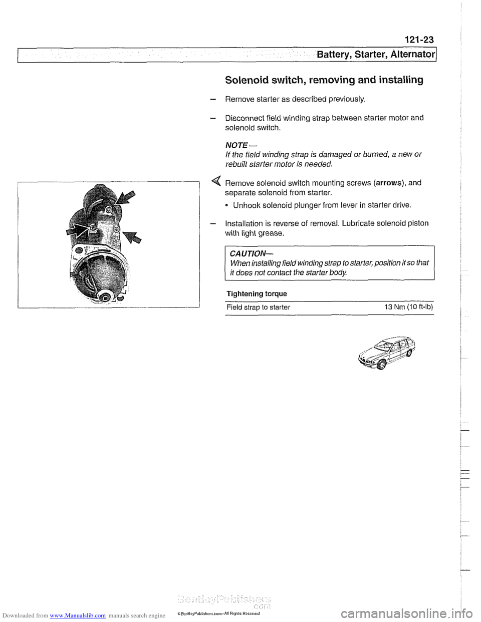
< Remove solenoid switch mounting screws (arrows), and
separate solenoid from starter.
Unhoolc solenoid plunger from lever in starter drive
- Installation is reverse of removal. Lubricate solenoid piston
with light grease.
CAUTION- When installing field winding strap to starter, position
itso that
it does not contact the starter body.
Tightening torque
Field strap to starter
13 Nm (10 ff-lb)
Page 764 of 1002
Downloaded from www.Manualslib.com manuals search engine
This repair group covers brake service:
Brake pads, calipers, and disks
Master cylinder, bralte booster, and parking brake
ABS
1 ASC and ABS / DSC component replacement
ABS
1 ASC and ABS 1 DSC system descriptions are covered
in
300 Suspension, Steering and Brakes - General.
Special Tools
BMW requires the use of either the DIS or the MoDiC diag-
nostic tool to safely and completely bleed the
brak~ng and
traction control systems. Read all procedures through before
beginning a job.
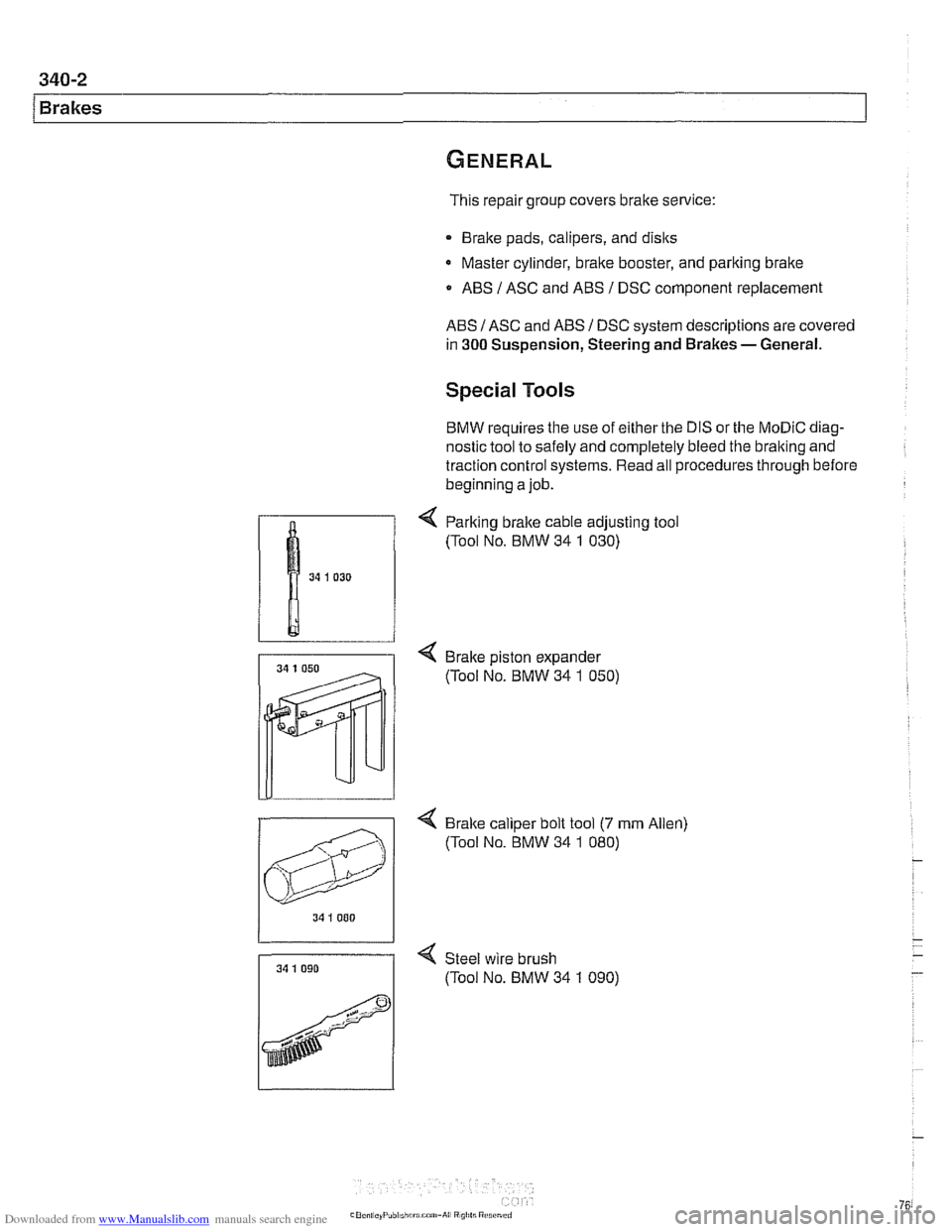
< Parking bralte cable adjusting tool
(Tool No. BMW 34
1 030)
4 Brake piston expander
(Tool No. BMW 34
1 050)
4 Bralte caliper bolt tool (7 mrn Allen)
(Tool No. BMW 34
1 080)
34 I 000
34 1 090 < Steel wire brush
7 (Tool No. BMW 34 1 090)
Page 766 of 1002
Downloaded from www.Manualslib.com manuals search engine
E39 brake system
BMW E39 models are equipped with vacuum power-assisted
four-wheel disc brakes with an integral
Antilock Brake System
(ABS). Single-piston calipers act on vented front and rear ro-
tors. A brake pad wear sensor for each axle indicates when
brake pads need replacement. The dual drum-type parking
brake system is integrated with the rear brake rotors.
Electronic braking and stability control
E39 models were introduced with Automatic Stability Control,
a computer controlled traction control system that uses the
AB5 system in conjunction with engine management controls
to control wheel spin during take-off and maintain vehicle sta-
bility while braking.
Added in the
1998 model year was Dynamic Stability Control
(DSC). This system implements wheel speed modulation
throughout all stages of driving. For example, DSC is able to
reduce understeer by applying differing amounts of braking
force to each wheel, or it can override the engine manage-
ment system during hard cornering.
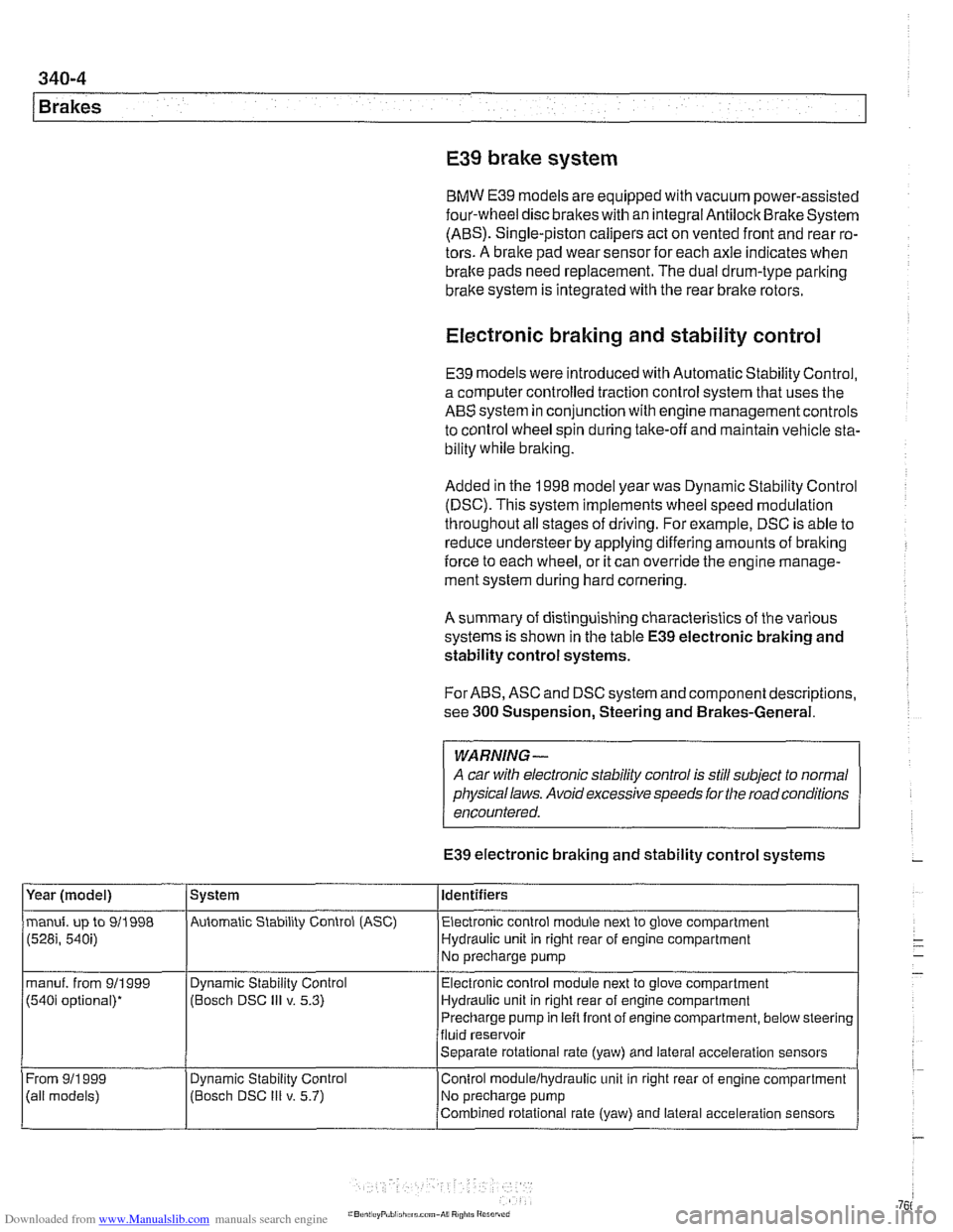
A summary of distinguishing characteristics of the various
systems is shown in the table
E39 electronic braking and
stability control systems.
For ABS, ASC and DSC system and component descriptions,
see
300 Suspension, Steering and Brakes-General.
WARNING-
A car with electronic stability control is still subject to normal
physical laws. Avoid excessive speeds for the road conditions
encountered.
E39 electronic braking and stability control systems
Year (model)
manuf. up to 911998
(528i, 540i)
manuf. from 911999
(540i optional)*
From
911 999
(ail models) System
Automatic Stability Control (ASC) Identifiers
Electronic control module next to glove compartment
Hydraulic unit in right rear of engine compartment
No precharge pump
Dynamic Stability Control
(Bosch DSC
Ill v. 5.3)
Dynamic
Stabil~ty Control
(Bosch DSC
Ill v. 5.7) Electronic
control module next to glove compartment
Hydraulic unit in right rear of engine compartment
Precharge pump in left front of engine compartment, below steering
fluid reservoir
Separate rotational rate (yaw) and lateral acceleration sensors
Control
modulelhydraulic unit in right rear of engine compartment
No precharge pump
Combined rotational rate (yaw) and lateral acceleration sensors
Page 774 of 1002
Downloaded from www.Manualslib.com manuals search engine
340-1 2
Brakes Brake pads, checking and replacing
Brake pads can be replaced without disconnecting the brake
fluid hose from the caliper or having to bleed the brakes. The
rotors can be replaced without disassembling wheel hub and
bearing. Always machine or replace rotors in pairs. Replace
pads in sets.
Front and rear brake pad replacement procedures are identical.
WARNING -
* Altllough semi-metallic andmetallic brale friction materials
in brake pads or shoes no longer contain asbestos, they
produce dangerous dust.
Treat all
brale dust as a hazardous material.
Do not create dust by grinding, sanding, or cleaning
brake friction surfaces with compressed air.
CAUTION--
Pressing caliper piston in may cause brake fluid reservoir to
overflow To prevent this, use a clean syringe to first remove
some fluid
from reservoir.
Raise car and remove wheels,
WARNING-
Make sure that the car is firmly supported on jack stands de-
signed for the purpose. Place jack stands beneath structural
chassis points. Do not place jack stands under suspension
parts.
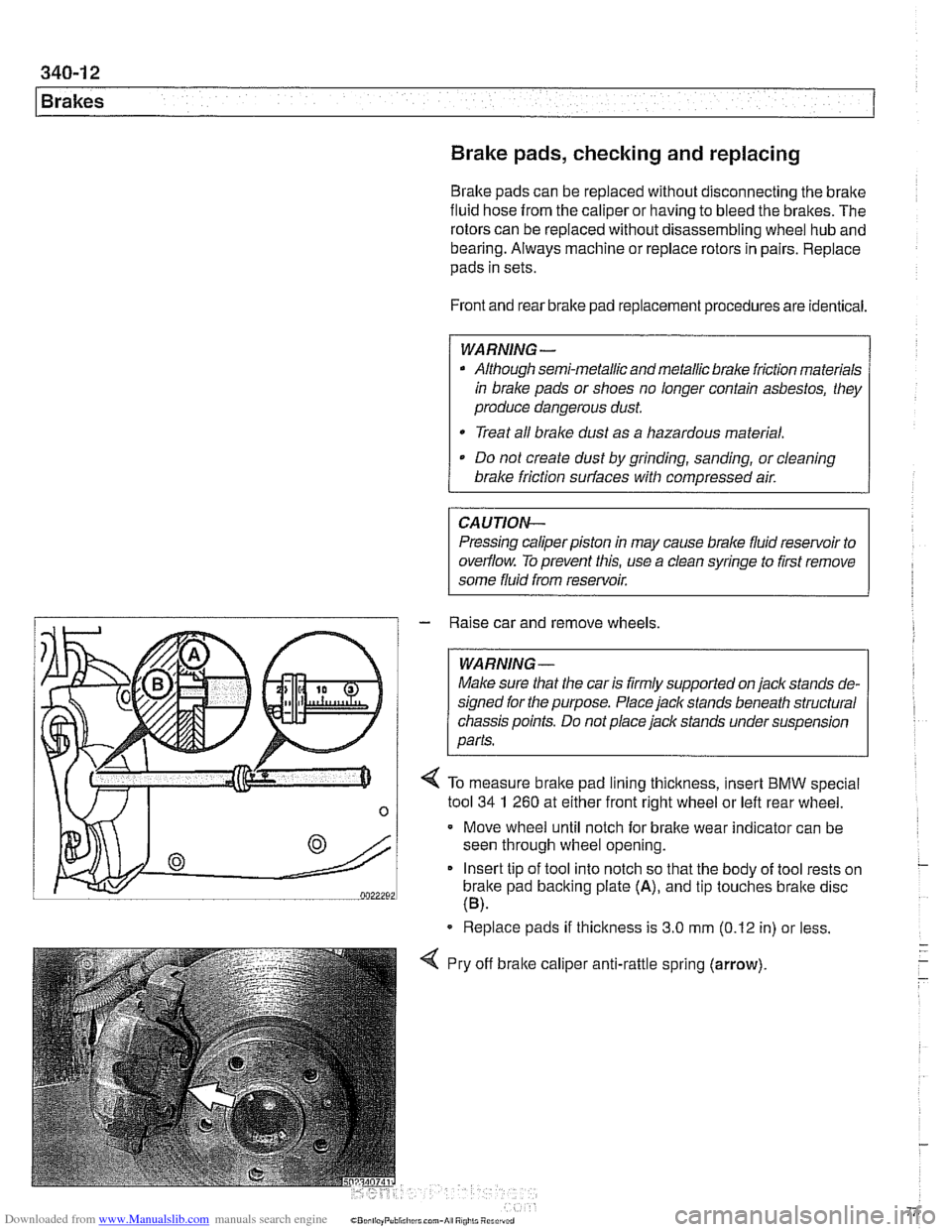
/ 4 To measure brake pad lining thickness, insert BMW special
n 1 tool 34 1 260 at either frontilght wheel or left rear wheel -
Move wheel until notch for brake wear indicator can be
seen through wheel opening.
Insert tip of tool into notch so that the body of tool rests on
brake pad backing plate
(A), and tip touches bralte disc
(B).
Replace pads if thickness is 3.0 mm (0.12 in) or less.
Pry off
bralte calipe~ , anti-rattle spring (arrow).
Page 775 of 1002
Downloaded from www.Manualslib.com manuals search engine
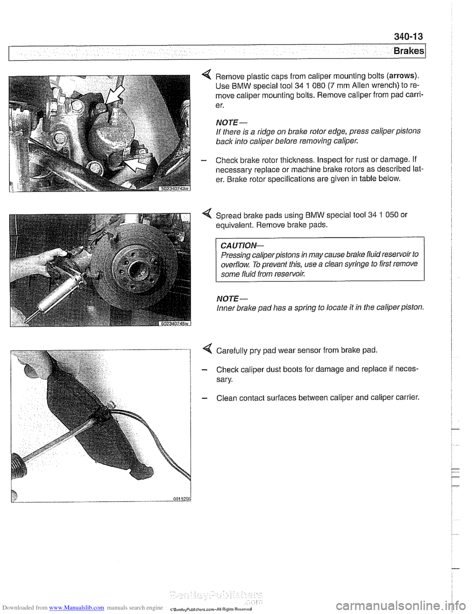
4 Remove plastic caps from caliper mounting bolts (arrows).
Use BMW special tool 34 1 080 (7 mm Alien wrench) to re-
move caliper mounting bolts. Remove caliper from pad
carri-
e r.
NOTE-
If there is a ridge on brake rotor edge, press caliper pistons
back into caliper before removing caliper.
- Check brake rotor thickness. Inspect for rust or damage. if
necessary replace or machine brake rotors as described lat-
er. Bralte rotor specifications are given in table below.
Spread bralte pads using BMW special tool
34 1 050 or
equivalent. Remove brake pads.
CA UTIOG
Pressing caliperpistons in may cause brake fluid reservoir to
overflow. To prevent this, use a clean syringe to first remove
some fluid from reservoir.
NOTE-
Inner brake pad lias a spring to locate it in the caliper piston.
4 Carefully pry pad wear sensor from brake pad
- Check caliper dust boots for damage and replace if neces-
sary.
- Clean contact surfaces between caliper and caliper carrier.
C"..., I,.. P,hi..,,,.r.. mm-*ii Ai"i,li "1.i"~"d