piston BMW 528i 1997 E39 User Guide
[x] Cancel search | Manufacturer: BMW, Model Year: 1997, Model line: 528i, Model: BMW 528i 1997 E39Pages: 1002
Page 160 of 1002
Downloaded from www.Manualslib.com manuals search engine
. .- --
I Cylinder Head Removal and Installation
- Evaluate cylinder head as described in 116 Cylinder head
and valvetrain.
Left cylinder head, installing, M62 engine
- Clean cylinder head and block sealing surfaces of gasket
debris, making sure no debris drops into coolant or oil pas-
sages.
- Clean cylinder head bolt holes and check condition of
threads.
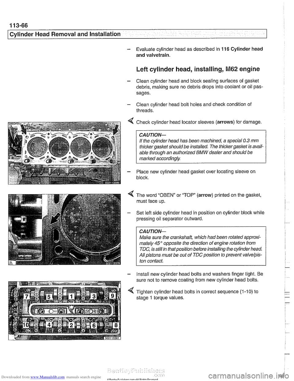
< Check cylinder head locator sleeves (arrows) for damage.
If the cylinder head has been machined, a special
0.3 mm
thicker gasket should be installed. The thicker gasket is avail-
able through an authorized
BMW dealer and should be
marked accordingly.
- Place new cylinder head gasket over locating sleeve on
block.
The word
"OBEN" or "TOP" (arrow) printed on the gasket,
must face up.
Set lefl side cylinder head in position on cylinder block while
pressing oil separator outward.
CAUJION-
Male sure the crankshaft, which had been rotated approxi-
mately
45" opposite the direction of engine rotation from
TDC, is still in thatposition before installing the cylinder head.
All pistons must be out of
TDCposition to prevent valvelpis-
ton contact.
- Install new cylinder head bolts and washers finger tight. Be
sure not to remove coating from new cylinder head bolts.
4 Tighten cylinder head bolts in correct sequence (1-10) to
stage
1 torque values.
Page 168 of 1002
Downloaded from www.Manualslib.com manuals search engine
11 3-74
Cylinder Head Removal and Installation
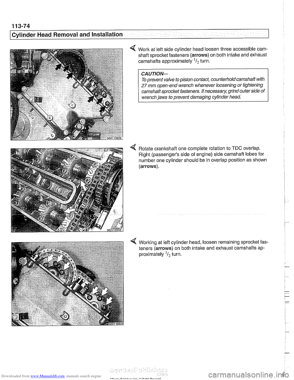
4 Work at left side cylinder head loosen three accessible cam- shaft sprocket fasteners (arrows) on both intake and exhaust
camshafts approximately
'I2 turn.
Toprevent valve
topiston contact, counterholdcamshaft with
27 mm open-end wrench whenever loosening or tightening
camshaft sprocket fasteners. If
necessarq! grind outer side of
wrench jaws to prevent damaging cylinder head.
4 Rotate crankshaft one complete rotation to TDC overlap.
Right (passenger's side of engine) side camshaft lobes for
number one cylinder should be in overlap position as shown
(arrows).
4 Working at left cylinder head, loosen remaining sprocket fas-
teners (arrows) on both
intake and exhaust camshafts ap-
proximately
'I2 turn.
Page 171 of 1002
Downloaded from www.Manualslib.com manuals search engine
Cvlinder Head Removal and Installation /
Right cylinder head, installing, M62 engine
- Clean cylinder head and block sealing surfaces of gasket de-
bris, making sure no debris drops into coolant or oil passag-
es.
CA UTIOW-
To prevent valve to piston contact when tightening camshaft
sprocket fasteners, counterhold camshaft with
27 mm open-
end wrench. If
necessarq: grind outer side of wrench jaws to
prevent damaging cylinder head.
- Check cylinder head bolt holes and condition of threads. Re-
move debris and liquids from holes.
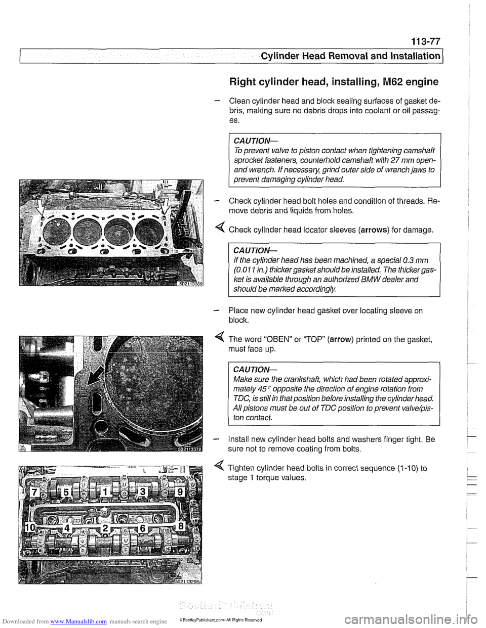
4 Check cylinder head locator sleeves (arrows) for damage
CAUTION-
lithe cylinder head has been machined, a special 0.3 rnm
(0.01 1 in.) thickergasket should be installed. The thickergas-
ket is available through an authorized BMW dealer and
should be marked
accordinglw
- Place new cylinder head gasket over locating sleeve on
block.
< The word "OBEN" or "TOP (arrow) printed on the gasket.
must face up.
CAUTION-
Male sure the crankshaft, which had been rotated approxi-
mately
45" opposite the direction of engine rotation from
TDC, is
stillin thatposition before installing the cylinder head.
All pistons must be out of
TDCposition to prevent valve/pis-
ton contact
- Install new cylinder head bolts and washers finger tight. Be
sure not to remove coating from bolts.
4 Tighten cylinder head bolts in correct sequence (1 -10) to
stage
1 torque values.
Page 193 of 1002

Downloaded from www.Manualslib.com manuals search engine
Cylinder Head and Valvetrain
4 Secure hydraulic lifters in lifter bores using BMW special tool
11 3 250, or remove lifters using a magnetic pick-up tool.
4 Remove camshaft bearing carrier from cylinder head.
CA UTION-
Camshaftbearing carriers must be reinstalledin their original
/ locations (E for ir;fal
Do not let hydraulic lifters fall out as the camshaft carrier is
removed.
Hydraulic lifters should be stored in an upright position.
Used hydraulic lifters
must be replaced into original lifter
bores.
Camshafts and lifters, installing
(M52 Engine)
Lubricate camshafts, camshaft carriers, bearing caps, hy-
draulic liflers, friction washers, splined shafts and spline hubs
with assembly lubricant before installation.
Make sure
the cranltshaft, which had been rotated approxi-
mately
30" opposite the direction of engine rotation from
TDC, is still in thatposition before lowering the
camshaffs into
position. All pistons must be out of TDC position to prevent
valve/piston interference when the camshalts are installed.
Before installing camshaft carriers, examine bearing bores
(arrows) on hydraulic lifter bores for signs of wear.
Page 194 of 1002
Downloaded from www.Manualslib.com manuals search engine
116-18
Cylinder Head and Valvetrain
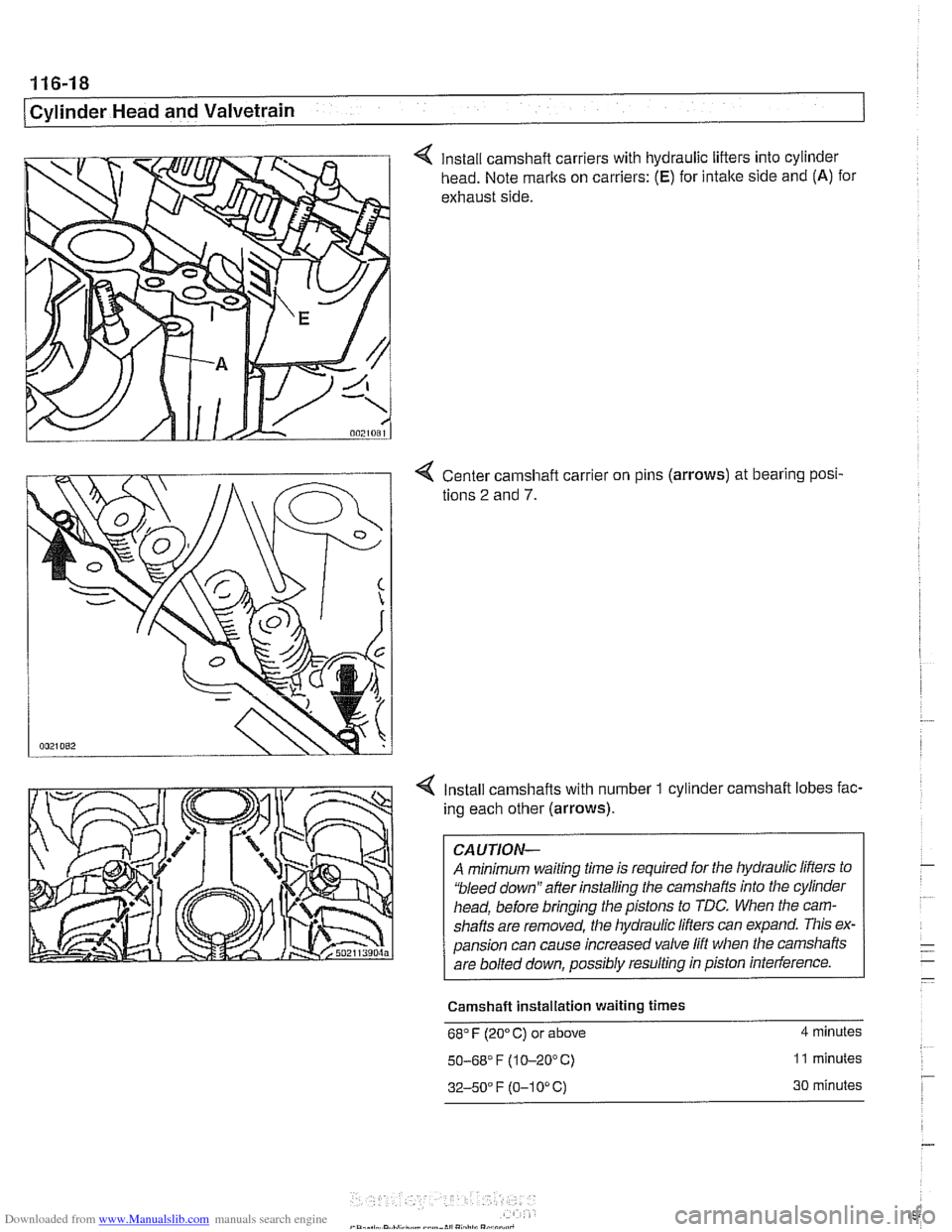
4 Install camshaft carriers with hydraulic lifters into cylinder
head. Note marks on carriers:
(E) for intake side and (A) for
exhaust side.
4 Center camshaft carrier on pins (arrows) at bearing posi-
tions
2 and 7.
4 Install camshafts with number 1 cylinder camshaft lobes fac-
ing each other (arrows).
CAUTION-
A minimum waiting time is required for the hydraulic lifters to
'bleed down" after installing the camshafts into the cylinder
head, before bringing the pistons to TDC. When the cam-
shafts are removed, the hydraulic
lifers can expand. This ex-
pansion can cause increased valve lift when the camshafts
are bolted down, possibly resulting in piston interference.
Camshaft Installation waiting
times
68" F (20" C) or above 4 minutes
50-68' F (1 0-20°C) 11 minutes
32-50" F (0-1 0" C) 30 minutes
Page 201 of 1002
Downloaded from www.Manualslib.com manuals search engine
Cylinder Head and Valvetrain
NOTE-
The camshaft bearing caps are coded with a letter and a
number. For example, "A
1" is the first exhaust camshaft
bearing cap
at the front of the engine, and "El "is the intake
camshaft bearing cap at the front of the engine.
-. -
The camshafts are stamped with a code letter - "E for the
intake side and
'X" for the exhaust side.
"E is for Einlap. (German for intake) and 'XA7s for Auspuff.
(German for exhaust).
- Repeat procedure for exhaust camshaft
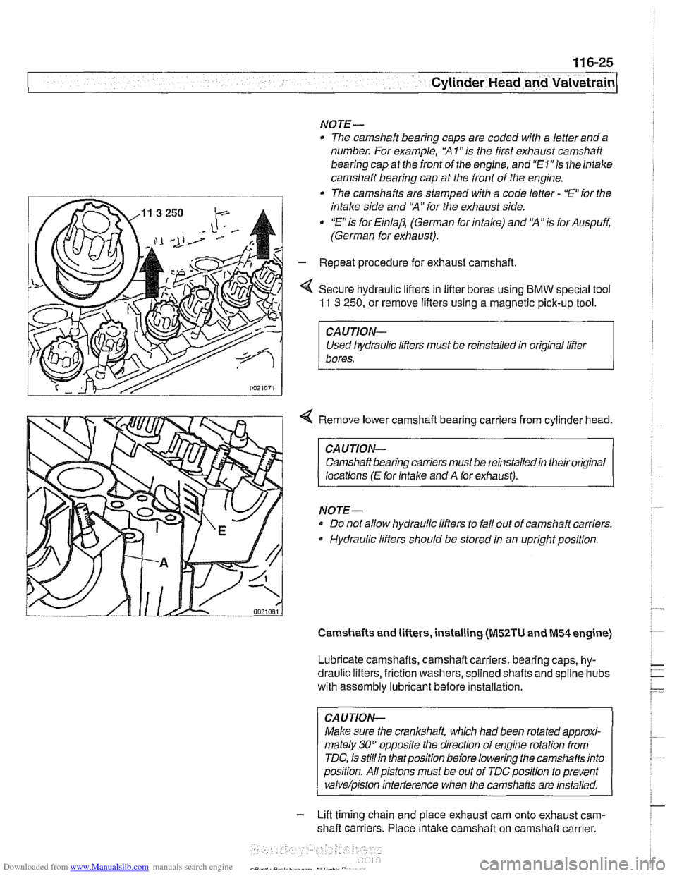
< Secure hydraulic lifters in lifter bores using BMW special tool
11 3 250, or remove lifters using a magnetic pick-up tool.
I CAUTION-
Used liydraulic lifters must be reinstalled in original lifter
1 bores.
4 Remove lower camshaft bearing carriers from cylinder head.
CAUTION- Camshaft bearing carriers must be reinstalled in their original
locations
(E for intalce and A for exhaust).
NOTE- Do not allow hydraulic lifters to fall out of camshaft carriers.
Hydraulic lifters should be stored in an upright position.
Camshafts and lifters, installing (M52TU and M54 engine)
Lubricate camshafts, camshaft carriers, bearing caps, hy-
draulic lifters, friction washers, splined shafts and
spline hubs
with assembly
lubricant before installation.
CAUTION-
Make sure the crankshaft, which had been rotated approxi-
mately
30" opposite the direction of engine rotation from
TDC, is
stillin thatposition before lowering the camshafts into
position. Allpistons must be out of
TDCposition to prevent
valve/piston inteiference when the carnshafis are installed.
- Lift timing chain and place exhaust cam onto exhaust cam-
shaft carriers. Place
intake camshaft on camshaft carrier.
Page 203 of 1002
Downloaded from www.Manualslib.com manuals search engine
-- - . .- -,
Cylinder Head and Valvetrain
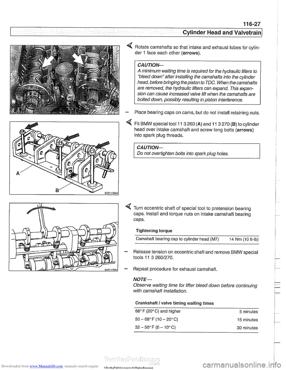
4 Rotate camshafts so that intalte and exhaust lobes for cylin-
der
1 face each other (arrows).
CAUJION-
A minimum waiting time is required for the hydraulic lifters to
'bleed down"after installing the camshafts into the cylinder
head, before bringing the piston to TDC. When the camshafts
are removed, the hydraulic lifters can expand. This expan-
sion can cause increased valve lift when the camshafts are
bolted down, possibly resulting in piston interference.
Place bearing caps on cams, but do not install retaining nuts.
4 Fit BMW special tool 11 3 260 (A) and 11 3 270 (B) to cylinder
head over
intalte camshaft and screw long bolts (arrows)
into spark plug threads.
CA UTION-
Do not overtighten bolts into spark plug holes.
< Turn eccentric shaft of special tool to pretension bearing
caps. Install and torque nuts on intake camshaft bearing
caps.
Tightening torque Camshaft bearing cap
to cylinder head (M7) 14 Nm (10 it-ib)
- Release tension on eccentric shaft and remove BMW special
tools
11 3 2601270.
- Repeat procedure for exhaust camshaft.
NOTE-
Observe waiting time for lifter bleed down before continuing
with camshaff installation.
Crankshaft
I valve timing waiting times
68°F (20°C) and higher 5 minutes
50-6S°F(10-20°C) 15 minutes
32-50DF(O-10°C) 30 minutes
Page 250 of 1002
Downloaded from www.Manualslib.com manuals search engine
I Camshaft Timing Chain
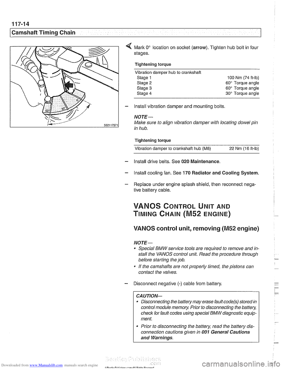
Mark 0" location on socket (arrow). Tighten hub bolt in four
stages.
Tightening torque Vibration damper
hub to cranlrshaft
Stage 1 100 Nm (74 it-lb)
Stage
2 60" Torque angle
Stage
3 60" Torque angle
Stage
4 30" Torque angle
- install vibration damper and mounting bolts
NOTE-
Male sure to align vibration damper with locating dowel pin
in hub.
Tightening torque Vibration damper to
cranltshait hub (ME) 22 Nm (16 ft-lb)
- Install drive belts. See 020 Maintenance.
- Install cooling fan. See 170 Radiator and Cooling System.
- Replace under engine splash shield, then reconnect nega-
tive battery cable.
!/ANBS CONTROL UNIT AND
TIMING CHAIN (M52 ENGINE)
VANOS control unit, removing (M52 engine)
NOTE-
Special BMW service tools are required to remove and in-
stall the
VANOS control unit. Read the procedure through
before starting the job.
If the camshafts are notproperly timed, the pistons can
contact the valves.
- Disconnect negative (-) cable from battery.
CAUTION-
Disconnecting the battery may erase fault code(s) stored in
control module memory. Prior to disconnecting the
battev,
check for fault codes using special BMW diagnostic equip-
ment.
* Prior to disconnecting the battery, read the battery dis-
connection cautions given in
001 General Cautions
and Warnings.
Page 255 of 1002
Downloaded from www.Manualslib.com manuals search engine
Camshaft Timing chain1
VANOS control unit, installing (M52 engine)
CAUTION-
Incorrect installation of the VANOS control unit may result in
damage to the engine.
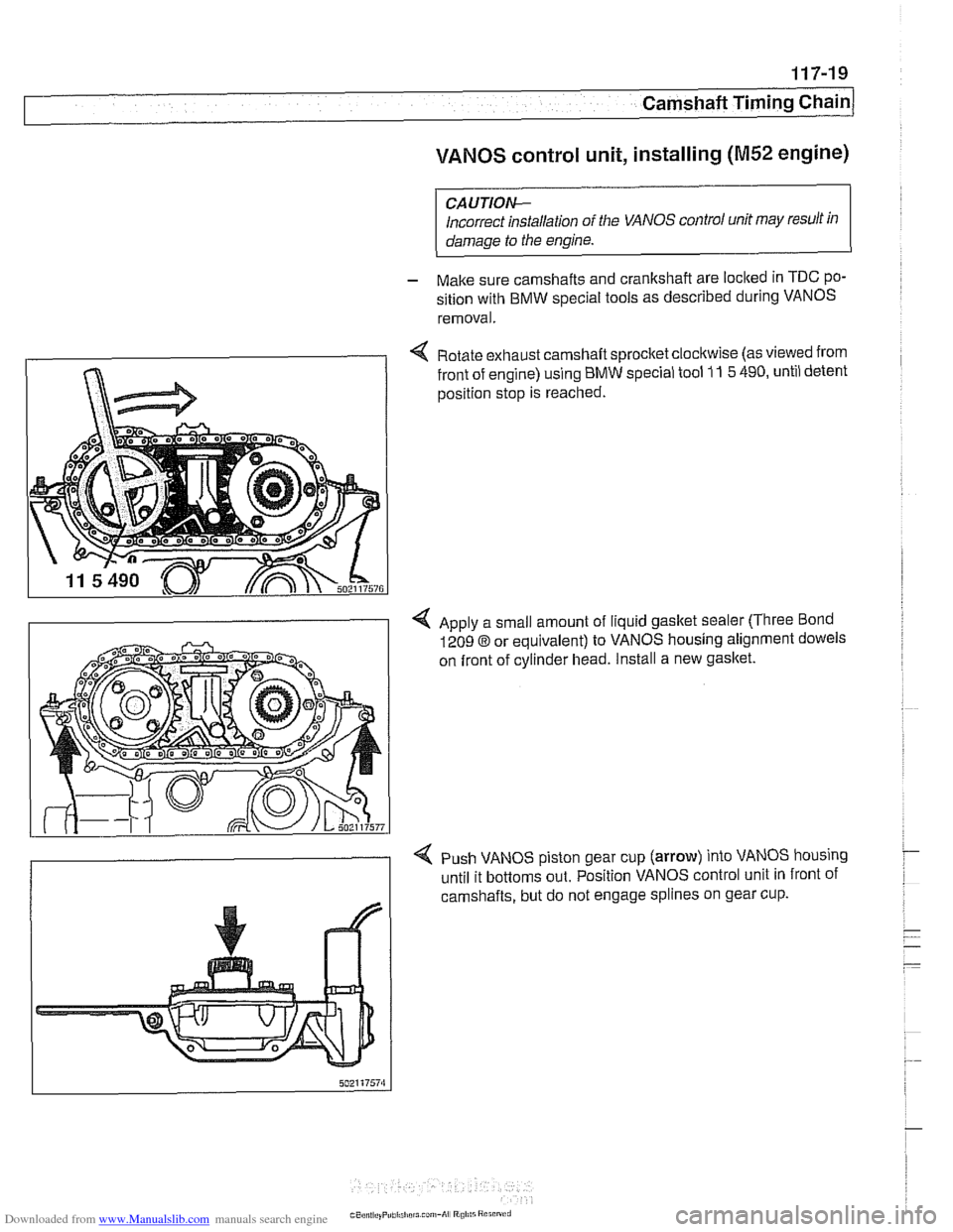
- Make sure camshafts and crankshaft are loclted in TDC po-
sition with BMW special tools as described during VANOS
removal.
< Rotate exhaust camshaft sprocket clocltwise (as viewed from
front of engine) using BMW special tool
11 5 490, until detent
position stop is reached.
4 Apply a small amount of liquid gasket sealer (Three Bond
1209
8 or equivalent) to VANOS housing alignment dowels
on front of cylinder head. Install a new
gasket.
< Push VANOS piston gear cup (arrow) into VANOS housing
until it bottoms out. Position VANOS control unit in front of
camshafts, but do not engage splines on gear cup.
Page 258 of 1002
Downloaded from www.Manualslib.com manuals search engine
Camshaft Timing Chain
VANOS timing, checking and adjusting
(M52 engine)
NOTE-
* Special BMW service tools are required to remove and in-
stall the VANOS control unit. Read the procedure through
before starting the job.
If the camshafts are not properly timed, the pistons can
contact the valves.
- Disconnect negative (-) cable from battery.
CAUTIOG Disconnecting the battery may erase
faultcode(s) storedin
control module memory. Prior to disconnecting the battery,
checlc for fault codes using special BMW diagnostic equip-
ment.
Prior to disconnecting the battery, read the battery dis-
connection cautions given in
001 General Cautions
and Warnings.
- Remove viscous clutch cooling fan. See 170 Radiator and
Cooling
System.
CAUTIOG The radiator cooling fan nut
(32 mm wrench) has left-hand
threads.
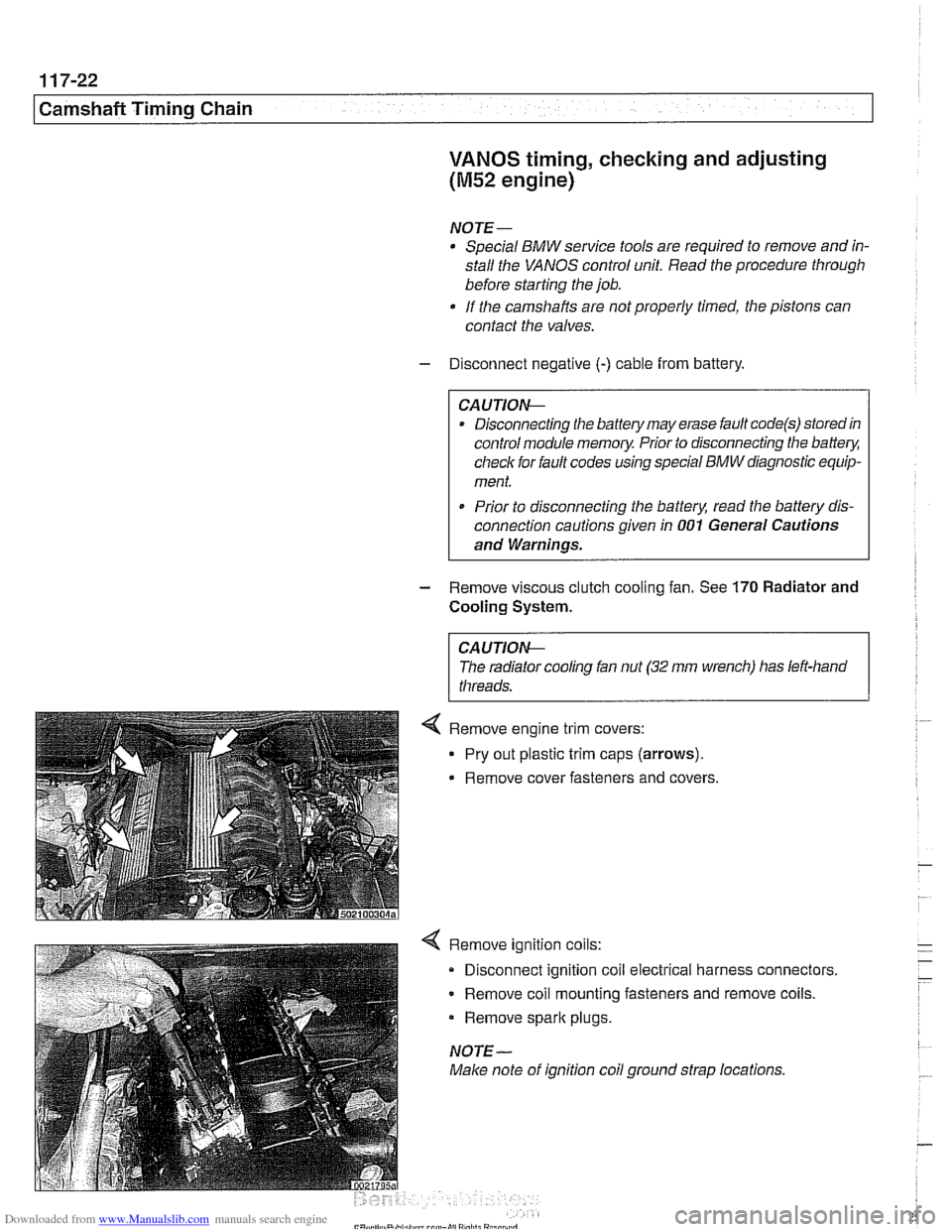
4 Remove ignition coils:
Disconnect ignition coil electrical harness connectors.
Remove coil mounting fasteners and remove coils.
Remove
spark plugs.
NOTE-
Make note of ignition coil ground strap locations.