high BMW 528i 1997 E39 Repair Manual
[x] Cancel search | Manufacturer: BMW, Model Year: 1997, Model line: 528i, Model: BMW 528i 1997 E39Pages: 1002
Page 833 of 1002
Downloaded from www.Manualslib.com manuals search engine
Trunk Lid, ~ail~atel
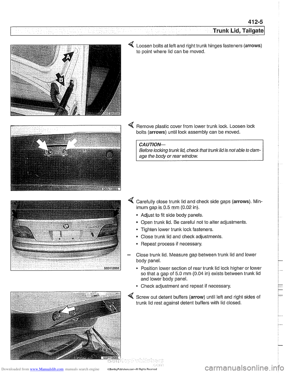
Loosen bolts at lefl and right trunk
to point where lid can be moved. hinges
fasteners (arrows)
4 Remove plastic cover from lower trunlc lock. Loosen lock
bolts (arrows) until lock assembly can be moved.
CAUTION-
Before locking trunklid, check that trunk lid is not able to dam-
age the body or rear window.
4 Carefully close trunk lid and check side gaps (arrows). Min-
imum gap is 0.5 mm (0.02 in).
Adjust to fit side body panels.
Open trunlc lid.
Be careful not to alter adjustments.
Tighten lower trunlc lock fasteners.
Close trunk lid and check adjustments.
Repeat process if necessary.
- Close trunk lid. Measure gap between trunlc lid and lower
body panel.
Position lower section of rear trunlc lid
lock higher or lower
so that a
ciao of 5.0 mm (0.04 in) exists between trunlc lid
and
lowe;body panel. '
Check adjustment and repeat if necessary,
4 Screw out detent buffers (arrow) until left and right sides of
trunk lid rest against detent buffers with lid closed.
Page 933 of 1002
Downloaded from www.Manualslib.com manuals search engine
Sunroof, adjusting
The sunroof is controlled by a set of cables that move the sun-
roof panel along guide rails when the motor is operated. The
sunroof can be adjusted without removing it from the car.
NOTE-
Be sure to check drains in front corners of sunroof carrier if
water is entering car through headliner.
- The sunroof panel should be adjusted under the following cir-
cumstances:
Sunroof misaligned with roof.
Sunroof does not close squarely.
* Wind noise at high speeds (sunroof closed).
Sunroof has been removed.
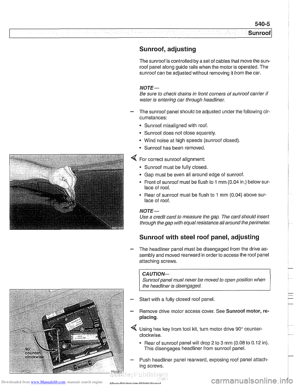
For correct sunroof alignment:
Sunroof must be fully closed.
Gap must be even all around edge of sunroof.
Front of sunroof must be flush to
1 mm (0.04 in.) below sur-
face of roof.
. Rear of sunroof must be flush to 1 mm (0.04) above sur-
face of roof.
NOTE-
Use a credit card to measure the gap. The card sllould insert
through the gap with equal resistance all around the perimeter.
Sunroof with steel roof panel, adjusting
- The headliner panel must be disengaged from the drive as-
sembly and moved rearward in order to access the roof panel
attaching screws.
CAUTIOI\C
Sunroof panel must never be moved to open position when . .
I the headliner is disenaaaed. 1
- Start with a fully closed roof panel.
- Remove drive motor access cover. See Sunroof motor, re-
placing.
Using hex key from tool kit, turn motor drive 90" counter-
clockwise.
Rear of sunroof panel will drop
2 to 3 mm (0.08 to 0.12 in).
This disengages headliner from sunroof panel.
- Push headliner panel rearward, exposing roof panel attach-
ing screws.
Page 935 of 1002
Downloaded from www.Manualslib.com manuals search engine
Sunroof
Sunroof with glass roof panel, adjusting - -
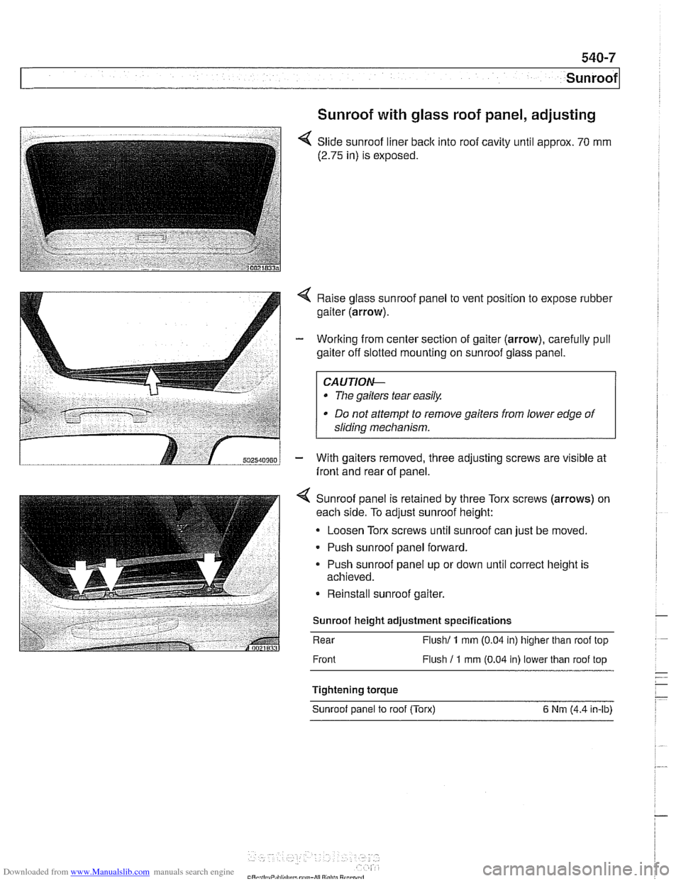
< Slide sunroof liner back into roof cavity until approx. 70 mm
(2.75 in) is exposed.
Raise glass sunroof panel to vent position to expose rubber
gaiter (arrow).
- Working from center section of gaiter (arrow), carefully pull
gaiter off slotted mounting on sunroof glass panel.
CA UTIOW-
The gaiters tear easik
* Do not attempt to remove gaiters from lower edge of
sliding mechanism.
- With gaiters removed, three adjusting screws are visible at
front and rear of panel.
4 Sunroof panel is retained by three Torx screws (arrows) on
each side. To adjust sunroof height:
Loosen Torx screws until sunroof can just be moved.
- Push sunroof panel forward.
Push sunroof panel up or down until correct height is
achieved.
Reinstall sunroof gaiter.
Sunroof height adjustment specifications
Rear
Flush1 1 rnrn (0.04 in) higher than roof top
Front Flush
11 rnrn (0.04 in) lower than roof top
Tightening torque Sunroof panel to roof (Torx)
6 Nrn (4.4 in-lb)
Page 952 of 1002
Downloaded from www.Manualslib.com manuals search engine
I Airbag System (SRS)
Two-stage airbag (MRS Ill)
Beginning with 2000 model year (911 999 production) the front
airbags were changed to a two-stage style airbag. This en-
sures that the force of
airbag inflation is not greater than nec-
essary to provide
protection. The airbags are designed to
Drovide "soit" de~lovment if the acceleration sensor detects a
iow-speed impact, and "hard deployment in higher speed im-
pacts.
NOTE-
A two-stage passenger airbag was used on cars built be-
tween
9/1998 and 3/1999. This pre-smart technology airbag
used two ignition stages. Stage one is designed to ignite first
during an impact. Stage two ignites after a timed period, as
programmed in the MRS
I1 control module.
Airbag indicator light
The MRS control module detects and stores system status
The
airbag indicator light in the instrument cluster displays
the status of the
airbag system when the ignition key is in "ac-
cessory" or
ON positions.
System normal: lndicator light comes on briefly, then goes
out.
- System malfunction: lndicator light fails to come on.
System malfunction: lndicator light comes on briefly, goes
out and lights up again.
The
airbag indicator light also comes on if the seat belt pyro-
technic tensioners have been triggered.
Page 965 of 1002
Downloaded from www.Manualslib.com manuals search engine
On-Board Diagnostics
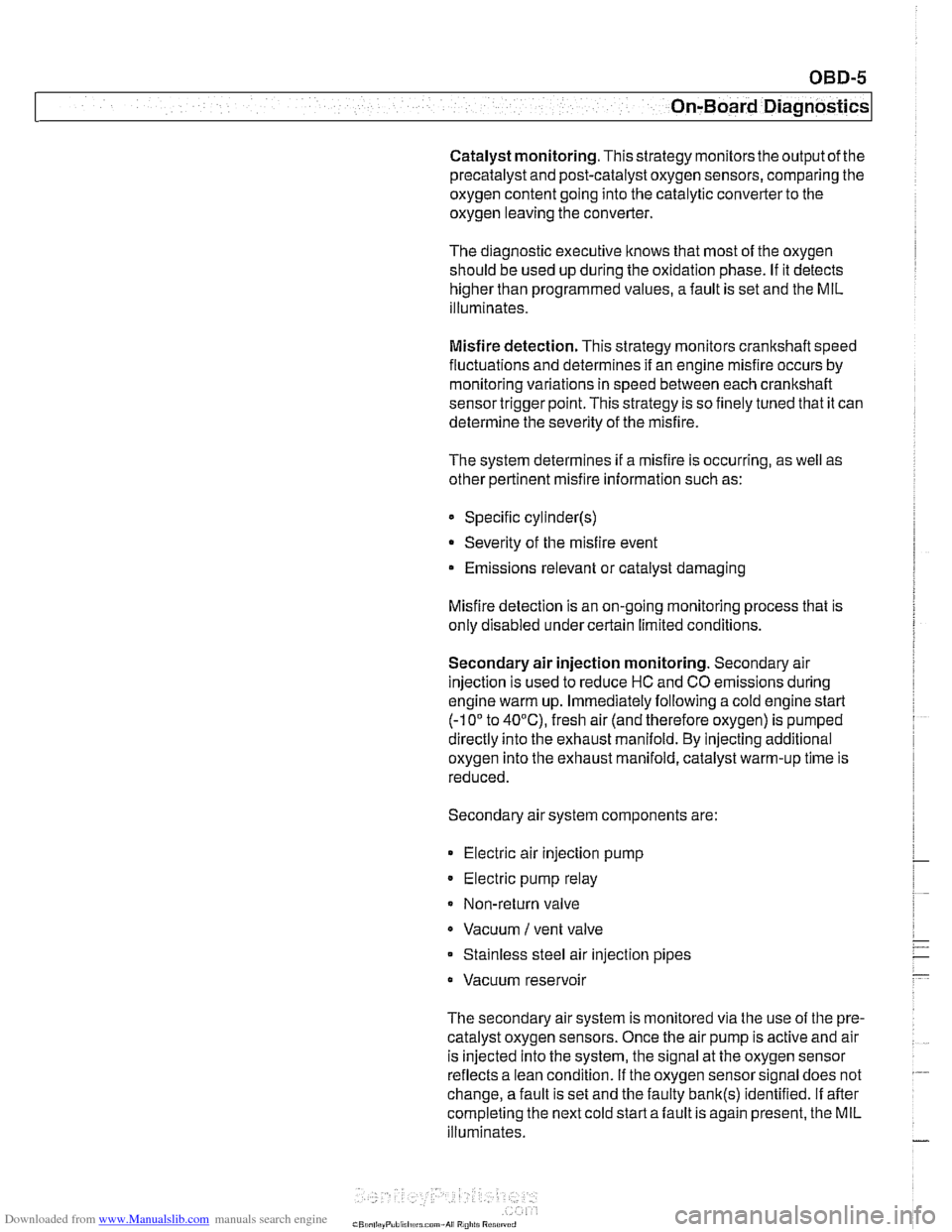
Catalyst monitoring. Thisstrategy monitors the outputofthe
precatalyst and post-catalyst oxygen sensors, comparing the
oxygen content going into the catalytic converter to the
oxygen leaving the converter.
The diagnostic executive
lknows that most of the oxygen
should be used up during the oxidation phase. If it detects
higherthan programmed values, afault is set and the MIL
illuminates.
Misfire detection. This strategy monitors crankshaft speed
fluctuations and determines if an enoine misfire occurs bv
monitoring variations in speed between each crankshaft
sensortrigger point. This strategy is so finely tuned that it can
determine the severity of the misfire.
The system determines
if a misfire is occurring, as well as
other pertinent misfire
information such as:
Specific
cylinder(s)
Severity of the misfire event
Emissions relevant or catalyst damaging
Misfire detection is an on-going monitoring process that is
only disabled under certain limited conditions.
Secondary air injection monitoring. Secondary air
injection is used to reduce HC and CO emissions during
engine warm up. Immediately following a cold engine start
(-1 0" to 40°C), fresh air (and therefore oxygen) is pumped
directly into the exhaust
manifold. By injecting additional
oxygen into the exhaust manifold, catalyst warm-up time is
reduced.
Secondary air system components are:
Electric air injection pump
* Electric pump relay
* Non-return valve
Vacuum
I vent valve
- Stainless steel air injection pipes
Vacuum reservoir
The secondary air system is monitored via the use
of the pre-
catalyst oxygen sensors. Once the air pump is active and air
is injected into the system, the signal at the oxygen sensor
reflects a lean condition. If the oxygen sensor signal does not
change, a fault is set and the faulty
bank(s) identified. If after
completing the next cold startafault is again present, the MIL
illuminates.
Page 971 of 1002
Downloaded from www.Manualslib.com manuals search engine
OBD-11
On-Board Diagnostics
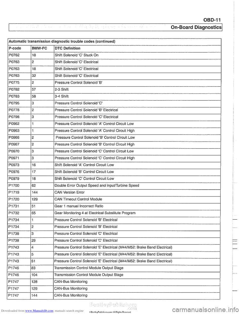
Automatic transmission diagnostic trouble codes (continued)
P-code
PO762
PO763
PO763
PO763
PO775
PO782
PO783 I I
PO795
PO798
PO962
PO963
PO966
PO967
PO970
PO971
BMW-FC
18
2 18
32
2
57
58
I I -
DTC Definition
Shift Solenoid 'C' Stuck On
Shift Solenoid
'C' Electrical
Shift Solenoid
'C' Electrical
Shift Solenoid
'C' Electrical
Pressure Control Solenoid
'B'
2-3 Shift
3-4 Shift
PO778 12 I Pressure Control Solenoid 'B' Electrical
3
3
1
1
2
2
3
3
PO973
PO979
PI 700
PI719
PI720
Pi731
PI732
PI734
Pressure Control Solenoid 'C'
Pressure Control Solenoid
'C' Electrical
Pressure Control Solenoid
'A' Control Circuit Low
Pressure Control Solenoid 'A' Control Circuit High
Pressure Control Solenoid
'6' Control Circuit Low
Pressure Control Solenoid
'0' Control Circuit High
Pressure Control Solenoid 'C' Control Circuit Low
Pressure Control Solenoid 'C' Control Circuit
High
PI734
PI738
Pi738
PO976 117 IShift Solenoid 'B' Control Circuit Low
16
18
62 144
129
51
65
1
PI743
PI743
PI743
PI746
PI746 - Pi747
Shift Solenoid 'A' Control Circuit Low
Shift Solenoid 'C' Control Circuit Low
Double Error Output Speed and
inputflurbine Speed
CAN Version Error
CAN
Timeout Control Module
Gear
1 manual Incorrect Ratio
Gear Monitoring 4 at Electrical Substitute Program
Pressure
Control Solenoid 'B' Eieclrical
2
3
29
PI747
PI747
Pressure Control Solenoid 'B' Electrical
Pressure Control Solenoid
'C' Electrical
Pressure Control Solenoid
'C' Electrical
4
5
51
83 104 Pressure Control Solenoid
'E' Electrical (M44lM52: Brake
Band Electrical)
Pressure Control Solenoid
'E' Electrical (M44lM52: Bralte Band Electrical)
Pressure Control Solenoid
'E' Electrical (M44lM52: Brake Band Electrical)
Transmission Control Module Output Stage
Transmission Control Module Output Stage
129 128 CAN-Bus Monitoring CAN-Bus Monitoring
144 CAN-Bus Monitoring
Page 972 of 1002
Downloaded from www.Manualslib.com manuals search engine
OBD-12
On-Board Diagnostics
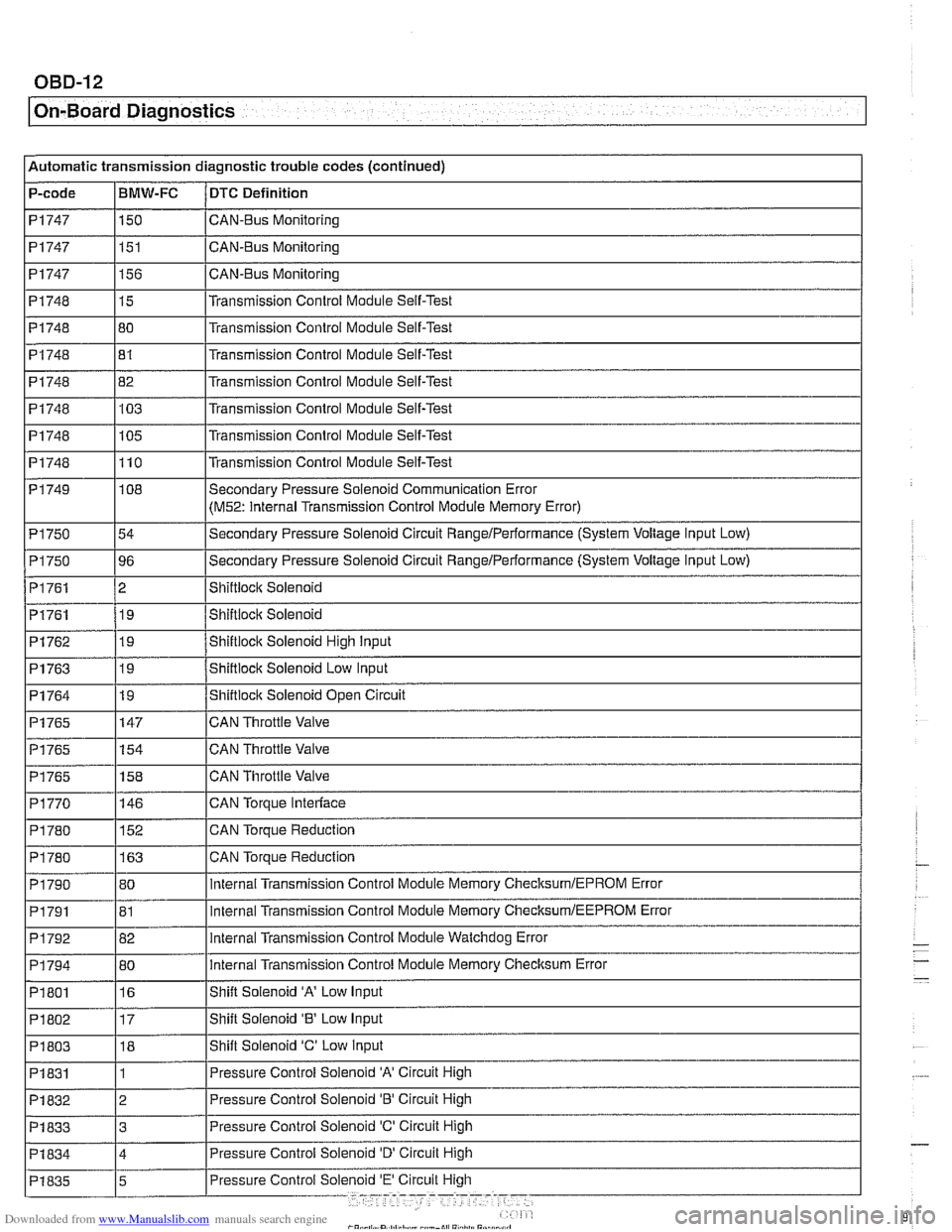
Automatic transmission diagnostic trouble codes (continued)
P-code
PI747
PI747
PI 747
PI748
PI748 I I
PI748
PI748
PI748
PI 748
PI 749
PI 750
P1750
PI761
PI761
BMW-FC
150
151
156
15
80
-- PI762
PI763
PI764
PI765
PI765
PI765
P1770
DTC Definition
CAN-BUS Monitoring
CAN-Bus Monitoring
CAN-Bus Monitoring
Transmission Control Module Self-Test
Transmission
Control Module Self-Test
PI748 182 l~ransmission Control Module Self-Test
81
103
105
110
I I
Transmission Control Module Self-Test
Transmission Control Module Self-Test
Transmission Control Module Self-Test
Transmission Control Module Self-Test
19
19
19
147
154
158
146
PI 790
PI791
P1792
PI 794
PI 801
P1802
PI 803
PI 831 Shiftiock Solenoid High input
Shiftlock Solenoid
Low Input
Shiftlock Solenoid Open Circuit
CAN Throttle Valve
CAN Throttle Valve
CAN Throttle Valve
CAN
Torpue Interlace
CAN Torque Reduction
PI 780
I I -
108
54
96
2 19
PI 780 1163 ICAN Torque Reduction
152
80
81
82
80
16
17 18
1 Secondary Pressure Solenoid Communication Error
(M52: Internal
Transmission Control Module Memory Error)
Secondary Pressure Solenoid Circuit
Rangelperformance (System Voltage Input Low)
Secondary Pressure Solenoid Circuit
RangeIPerformance (System Voltage Input Low)
Shiftioclc Solenoid
Shiftiocic Solenoid
internal Transmission Control Module Memory ChecksumlEPROM Error
internal Transmission Control Module Memory
ChecksumIEEPROM Error
internal Transmission Control Module Watchdog Error
internal Transmission Control Module Memory Checksum Error
Shift Solenoid
'A' Low Input
Shift Solenoid
'8' Low Input
Shift Solenoid
'C' Low input
Pressure Control Solenoid
'A' Circuit High
Pressure Control Solenoid 'B' Circuit High
PI832
PI833 13 IPressure Control Solenoid 'C' Circuit High
2
Page 973 of 1002
Downloaded from www.Manualslib.com manuals search engine
On-Board Diagnostics
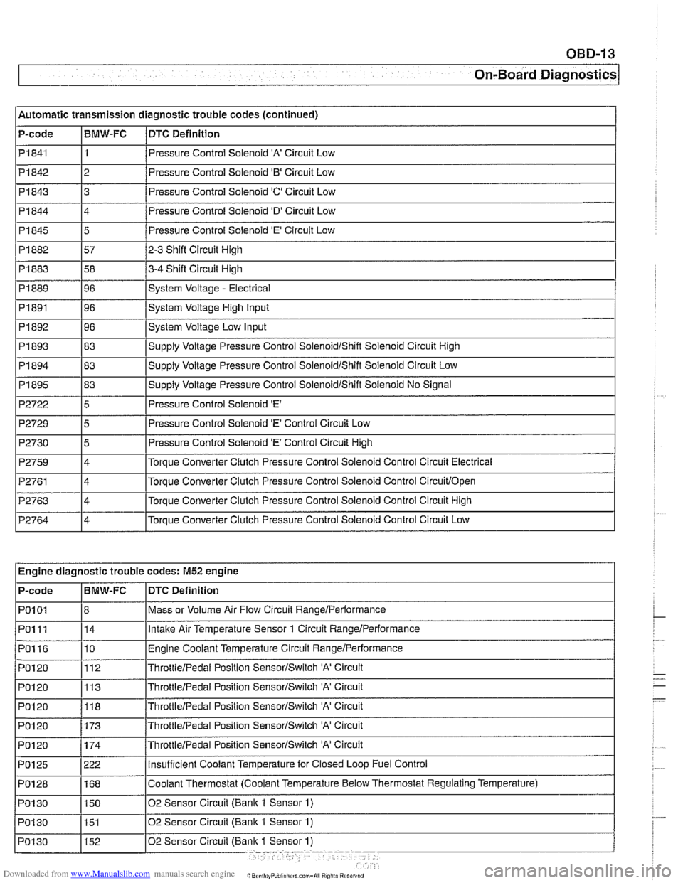
l~utomatic transmission diagnostic trouble codes (continued)
P-code
1 Pi844
I I
14 /Pressure Control Solenoid 'D' Circuit Low
I I PI841 11 /Pressure Control Solenoid 'A' Circuit Low
BMW-FC
Pi842
I
P2722 15 I Pressure Control Solenoid 'E' I
DTC
Definition
Pi 845
Pi 882
Pi 883
PI 889
PI891
PI 892
PI 893
Pi 843 3 8
2 Pressure Control Solenoid '0' Circuit Low
5
57
58
96
96
96
83
P2729
P2730
P2759
P2761
P2763
P2764
Pressure Control Solenoid 'E' Circuit Low
2-3 Shift Circuit High
3-4 Shift Circuit High
System Voltage
- Electrical
System Voltage High Input
System Voltage Low Input
SUDP~V Voltaqe Pressure Control SoienoidIShift Solenoid Circuit High
~~ ~~ ~ Engine diagnostic trouble codes: M52 engine
5
5
4
4
4
4
I I
Pressure Control Solenoid 'E' Control Circuit Low
Pressure Control Solenoid
'E' Control Circuit High
Torque Converter Clutch Pressure Control
Solenoid Control Circuit Electrical
Torque Converter Clutch Pressure Control Solenoid Control
Circuitlopen
Torque Converter Clutch Pressure Control Solenoid Control Circuit High
Torque Converter Clutch Pressure Control Solenoid Control Circuit Low
DTC Definition
Mass or Volume Air
Flow Circuit RangeIPerformance
lntalte Air Temperature Sensor 1 Circuit Rangelperformance
Engine Coolant Temperature Circuit RangeIPerformance
ThrottieIPedai Position SensorISwitch 'A' Circuit
ThrottleIPedai Position SensorISwitch 'A' Circuit
P-code
PO1
01
PO1 11
PO116
PO120
PO120
PO1 20 BMW-FC
8 14
10
112
113
POI 20 1173 /~hrottie/~edal Position SensorISwitch 'A' Circuit
118
ThrottieIPedai Position SensorISwitch 'A' Circuit
Page 975 of 1002
Downloaded from www.Manualslib.com manuals search engine
OBD-15
On-Board ~iagnosticsl
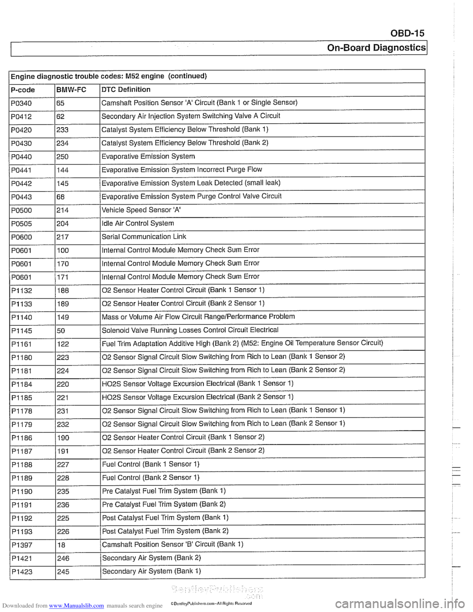
Engine diagnostic trouble codes: M52 engine (continued)
P-code
PO340
PO412
PO420
PO430
PO440
PO441
PO442
PO443
PO500
PO505
PO600
PO601
PO601
I PO601
~1132
~1133
BMW-FC
65
62
233
234
250 144
-
145
68
214
i I
DTC Definition
Camshalt Position Sensor 'A' Circuit (Bank 1 or Single Sensor)
Secondary Air Injection System Switching Valve A Circuit
Catalyst System Efficiency Below Threshold
(Bank 1)
Catalyst System Efficiency Below Threshold (Bank 2)
Evaporative Emission System
Eva~orative Emission Svstem Incorrect Purge Flow .
Evaporative Emission System Leak Detected (small leak)
Evaporative Emission System Purge Control Valve Circuit
Vehicle Speed Sensor 'A'
204
21 7
100
170
171
188
189
PI161
PI180
PI181
PI184
PI185
PI178
02 Sensor Heater Control Circuit (Bank 2 Sensor 2) I
idle Air Control System
Serial Communication
Link
Internal Control Module Memory Check Sum Error
Internal Control Module Memory
Check Sum Error
Internal Control Module Memory
Check Sum Error
02 Sensor Heater Control Circuit (Bank 1 Sensor
1)
02 Sensor Heater Control Circuit (Bank 2 Sensor 1)
Mass or Volume Air Flow Circuit RangeIPerlormance Problem PI140
I
I I
P1188 1227 I Fuel Control (Bank 1 Sensor 1)
PI145 150 /Solenoid Valve Running Losses Control Circuit Electrical
149
122
223
224
220 221
231
I I
P1189 1228 I Fuel Control (Banlc 2 Sensor 1)
Fuel Trim Adaptation Additive High (Bank 2) (M52: Engine Oil Temperature Sensor Circuit)
02 Sensor Signal Circuit Slow Switching from Rich to Lean
(Bank 1 Sensor 2)
02 Sensor Signal Circuit Slow Switching from Rich to Lean
(Bank 2 Sensor 2)
H02S Sensor Voltage Excursion Electrical (Banlc 1 Sensor 1)
HO2S Sensor Voltage Excursion Electrical (Banlc 2 Sensor 1)
02 Sensor Sianai Circuit Slow Switchina from Rich to Lean (Bank 1 Sensor 1)
02 Sensor Signal Circuit Slow Switching from Rich to Lean (Bank 2 Sensor 1) PI179
I I
PI190 1235 I Pre Catalyst Fuel Trim System (Banlc 1)
PI186 1190 102 Sensor Heater Control Circuit (Banlc 1 Sensor 2)
232
I I
PI191 1236 I Pre
Catalyst Fuel Trim System (Banlc 2)
PI192
. . -- - i Pi193 1226 I Post Catalvst Fuel Trim Svstem (Bank 2)
225
PI397
I I
Post Catalyst Fuel Trim System (Bank 1)
PI421 1246 /Secondarv Air System (Bank 2)
18
Secondary Air System (Bank
1) PI423
Camshaft Position Sensor '0' Circuit (Bank 1)
I 245
Page 977 of 1002
Downloaded from www.Manualslib.com manuals search engine
On-Board ~iaanosticsl
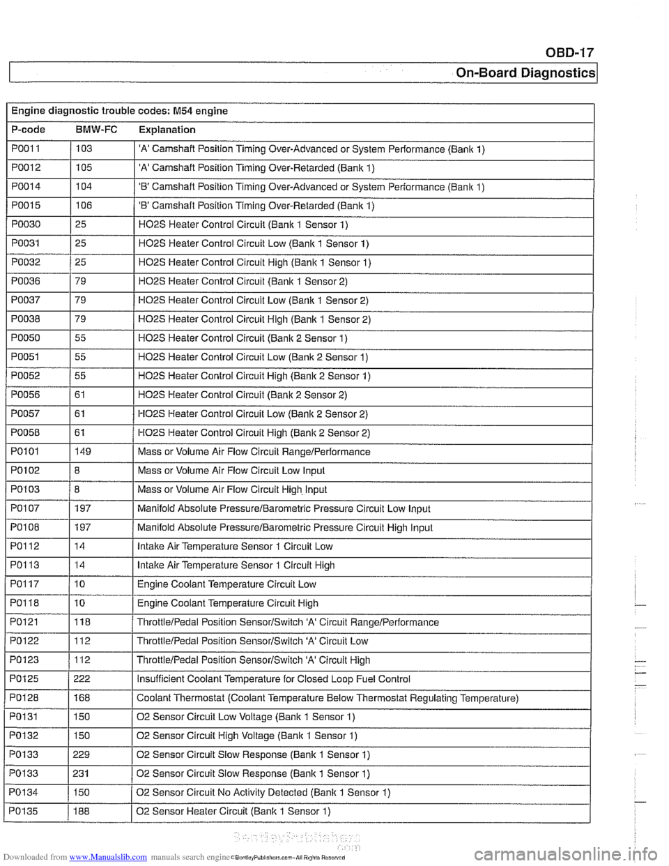
Engine diagnostic trouble codes: M54 engine
P-code
BMW-FC Explanation
PO01 I / 103 I 'A' Camshaft Position Timing Over-Advanced or System Performance (Banlc 1) I I
PO012 1105 I 'A' Camshaft Position Timing Over-Retarded (Bank 1) I I
PO01 4 1104 I 'B' Camshaft Position Timing Over-Advanced or System Performance (Bank 1)
PO01 5
PO030
PO031
PO032
I 1
PO038 179 / HO2S Heater Control Circuit High (Bank 1 Sensor 2)
I I -.
I I
PO050 1 55 I H02S Heater Control Circuit (Bank 2 Sensor 1)
106
25
25
25
PO036
I I
PO051 1 55 I H02S Heater Control Circuit Low (Bank 2 Sensor 1)
'B' Camshaft Position Timing Over-Retarded (Bank 1)
H02S Heater Control Circuit (Bank 1 Sensor 1)
H02S Heater Control Circuit Low (Bank 1 Sensor 1)
H02S Heater Control Circuit Hiqh (Bank 1 Sensor 1)
PO037 1 79 I HO2S Heater Control Circuit Low (Bank 1 Sensor 2)
79
HOPS Heater
Control Circuit (Banlc 1 Sensor 2)
PO052
PO056
PO057
PO058
I I
PO1 03 / 8 I Mass or Volume Air Flow Circuit High. Input
I I -.
I I
PO1 07 1 197 I Manifold Absolute PressureIBarometric Pressure Circuit Low Input
55
61
61
61
PO101
I I
POI08 1197 / Manifold Absolute PressureIBarometric Pressure Circuit High Input
H02S Heater Control Circuit High (Bank 2 Sensor 1)
H02S Heater Control Circuit (Bank 2 Sensor 2)
HO2S Heater Control Circuit Low (Bank 2 Sensor 2)
HO2S Heater Control Circuit Hiqh (Banlc 2 Sensor 2)
PO102 18 I Mass or Volume Air Flow Circuit Low Input
149
I I -
PO122 112 ThrottleIPedai Position SensorISwitch 'A' Circuit Low
PO123 1112 I ThrottleIPedal Position SensorISwitch 'A' Circuit High
Mass
or Volume Air Flow Circuit
RangeIPerformance
PO112
PO113
PO1 17
PO118
PO121
14
14
10
10
118
PO128
PO1 31
PO132
PO133
PO133
PO1 34 Intake
Air Temperature Sensor 1 Circuit Low
Intake Air Temperature Sensor 1 Circuit High
Engine Coolant Temperature Circuit Low
Engine Coolant Temperature Circuit High
ThrottleIPedal Position SensorISwitch 'A' Circuit RanqeIPerformance
I I
168
150
150
229
231
150
PO135
Coolant Thermostat (Coolant Temperature Below Thermostat Regulating Temperature)
02 Sensor Circuit Low Voltage (Bank 1 Sensor 1)
02 Sensor Circuit High Voltage (Bank 1 Sensor 1)
02 Sensor Circuit Slow Response (Bank
1 Sensor 1)
02 Sensor Circuit Slow Response
(Banlc 1 Sensor 1)
02 Sensor Circuit No Activitv Detected
(Banlc 1 Sensor 1)
188 02 Sensor Heater Circuit (Bank 1 Sensor 1)