jump start BMW 528i 1997 E39 Workshop Manual
[x] Cancel search | Manufacturer: BMW, Model Year: 1997, Model line: 528i, Model: BMW 528i 1997 E39Pages: 1002
Page 7 of 1002
Downloaded from www.Manualslib.com manuals search engine
001 General Warnings and Cautions
PLEASE READ THESE WARNINGS AND CAUTIONS
BEFORE PROCEEDING
WITH MAINTENANCE AND REPAIR WORK.
WARNINGS-
See also CAUTIONS
- Some repairs may be beyond your capability. If you lack the skills, - Catch draining fuel, oil, or brake fluid in suitable containers. Do
tools and equipment, or a suitable workplace for any procedure
not use
foodor beverage containers that might mislead someone
described in this manual, we suggest you leave such repairs to
into
drinking from them. Store flammable fluids away from fire
an authorized BMW dealer service department or other qualified
hazards. Wipe up spills at once, but do not store the oily rags,
shop. which can ignite and burn spontaneously.
. Do not reuse any fasteners that are worn or deformed. Many fas- Always observe good worRshop practices. Wear qoqqles when
teners are designed to be used only once and become
unreliable you operate machine tools or work with battery acid:kloves or
and mav fail when used a second time. This includes, but is not other
~rotective clothino should be worn whenever the iob re-
limited io, nuts, bolts, washers, self-locking nuts or bolts, clrclips yires' working with harmful substances.
and cotter pins. Always replace these fasteners with new parts.
Greases, lubricants and other automotive chemicals contain toxic
. Never work under a lifted car unless it is solidly supported on
substances, many of which are absorbed directly through the
stands
desiqned for the purpose. Do not supeort a car on cinder
skin. Read the manufacturer's instructions and warninos careful-
blochs, hollow tiles orotherbrops that may drurnbie undercontin-
uous toad. Never work under a car that is supported solely by a
iack. Never work under the car
while the enqine is runninq. - -
If you aregoing to work underacaron the ground, makesure that
the ground is level. Block the wheels to
keep the car from rolling.
Disconnect the battery negative
(-) terminal to prevent others
from starting the car while you are under it.
- Never run the engine unless the work area is well ventilated. Car-
bon monoxide kills.
Rings, bracelets and other jewelry should be removed so that
they cannot cause electrical shorts, get caught in running ma-
chinery, or be crushed by heavy parts.
- Tie long hair behind your head. Do not wear a necktie, a scarf.
loose clothing, or a necklace when you work near machine tools
or running engines. if your hair, clothing, or jewelry were to get
caught in the machinery, severe injury could result.
DO not attempt to
work on your car if you do not feel well. You in-
crease the
danger of injuryto yourseliand others if you are tired,
uDset or have taken medication or anv other substance that mav
keep you from being fully alert.
Illuminate your work area adequately but safely. Use a portable
iy. Use hand and eye protection. Avoid direct skin conGct.
Disconnect the battery negative (-) terminal whenever you work
on the fuel system
orthe electrical system. Do not smokeorwork
near heaters or other fire hazards. Keep an approved fire extin-
guisher handy.
. Friction materials (such as brake pads or shoes or clutch discs)
contain asbestos fibers or other friction materials. Do not create
dust by grinding, sanding, or by cleaning with compressed air.
Avoid breathing dust. Breathing any
friclion material dust can
lead to serious diseases and may result in death.
Batteries
giveoff explosive hydrogen gas during charging. Keep
sparks, lighted matches and open flame away from the top of the
battery. If hydrogen gas escaping from the cap vents is ignited, it
will ignite gas trapped in the cells and cause the battery to ex-
plode.
Connect and disconnect battery cables, jumper cables or a bat-
tery charger only wilh the ignition switched off. Do not disconnect
the battery while the engine is running.
Do not quick-charge the battery (for boost starting) for longer
than one minute. Wait at least one minute before boosting the
battery a second time.
. . safety lighiforworking lnsideor under the car. Make sure the bulb - Do not allow battery charging vollage to exceed 16.5 volts. If the
is enclosed bv a wire caoe. The hot filament of an accidentallv
batten! beoins ~roducina oas or boilino violentiv, reduce the
broken bulb can ignite spilled
fuel, vapors or oil. , - - - charglng rate. ~oostlng a sutfaled battery at a igh charging rate
can cause an
explosion.
-
Continued on next page
Page 11 of 1002
Downloaded from www.Manualslib.com manuals search engine
01 0-1
010 General
General ........................... .01 0.2
How to Use this Manual ............ .01 0.2
Warnings. cautions and notes ........... .0l 0.3
Getting Started .................... .0i 0.5
Safety ............................. .O1 0.5
Lifting the car ........................ .O1 0.5
Raising car ......................... .O1 0.5
Working under car .................... .O1 0.6
Advice for the Beginner ............ .O1 0.7
Planning ahead ...................... .O1 0.7
Workshop practices ................... .O1 0.7
Non-reusable fasteners ................ .O1 0.7
Tightening fasteners .................. .O1 0.8
Gaskets and seals .................... .O1 0.9
Electrical testing .................... .O1 0.10
Wire repairs ........................ .O1 0.10
Buying Parts ..................... .01 0.11
Genuine BMW parts ................. .O1 0.11
Non-returnable parts ................. .O1 0.11
Information you need to know .......... .0l 0.12
Service ........................... 01 0-1 3
TOOIS ............................. 010-13
Basic tool requirements ............... 01 0-1 4
Jack stands ......................... 01 0-1 6
Oil change equipment ................. 01 0-1 6
Torque wrench ...................... 01 0-17
Digital multimeter .................... 010-17
BMW special tools ................... 01 0-1 8
Emergencies ...................... 01 0-1 8
Changing a tire ...................... 01 0-1 8
Jump starting ....................... 01 0-1 9
Indicator and warning lights ............ 01 0-1 9
Towing ............................ 010-20
Spare parts kit ...................... 010-21
Page 29 of 1002
Downloaded from www.Manualslib.com manuals search engine
General
Cars with discharged or dead batteries can be jump-started
using the good battery from another car. See owner's manual
for proper instruction on jump starting. When jump-starling
the engine, always note the following warnings.
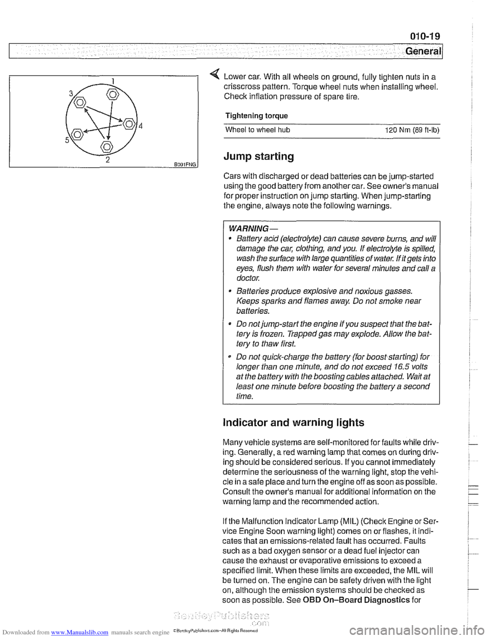
4 Lower car. With all wheels on ground, fully tighten nuts in a
WARNING-
* Battery acid (electrolyte) can cause severe burns, and will
damage the
cal; clothing, and you. If electrolyte is spilled,
wash the surface with large quantities of water.
M itgets into
eyes, flush them with water for several minutes and call a
doctor.
B4
5
43
2 BOOIFNG.
Batteries produce explosive and noxious gasses.
Keeps sparks and flames away. Do not smoke near
batteries.
Do notjump-start the engine
ifyou suspect that the bat-
tery is frozen. Trappedgas may explode. Allow the bat-
tery to thaw first.
Do not quick-charge the battery (for boost starting) for
longer than one minute, and do not exceed
16.5 volts
at the battery with the boosting cables attached. Wait at
least one minute before boosting the battery a second
time.
crisscross pattern.
Torque wheel nuts when installing wheel.
Check inflation pressure of spare tire.
Tightening torque
Wheel to wheel hub 120 Nm (89 ft-ib)
Jump starting
Indicator and warning lights
Many vehicle systems are self-monitored for faults while driv-
ing. Generally,
a red warning lamp that comes on during driv-
ing should be considered serious. If you cannot immediately
determine the seriousness of the warning light, stop the vehi-
cle in a safe place and turn the engine off as soon as possible.
Consult the owner's manual for additional information on the
warning lamp and the recommended action.
If the Malfunction Indicator Lamp (MIL)
(Check Engine or Ser-
vice Engine Soon warning light) comes on orflashes, it indi-
cates that an emissions-related fault has occurred. Faults
such as a bad oxygen sensor or a dead fuel injector can
cause the exhaust or evaporative emissions to exceed a
specified limit. When these limits are exceeded, the MIL will
be turned on. The engine can be safety driven with the light
on, although the emission systems should be
checked as
soon as possible. See OBD On-Board Diagnostics for
Page 77 of 1002
Downloaded from www.Manualslib.com manuals search engine
Engine Removal and lnstallationl
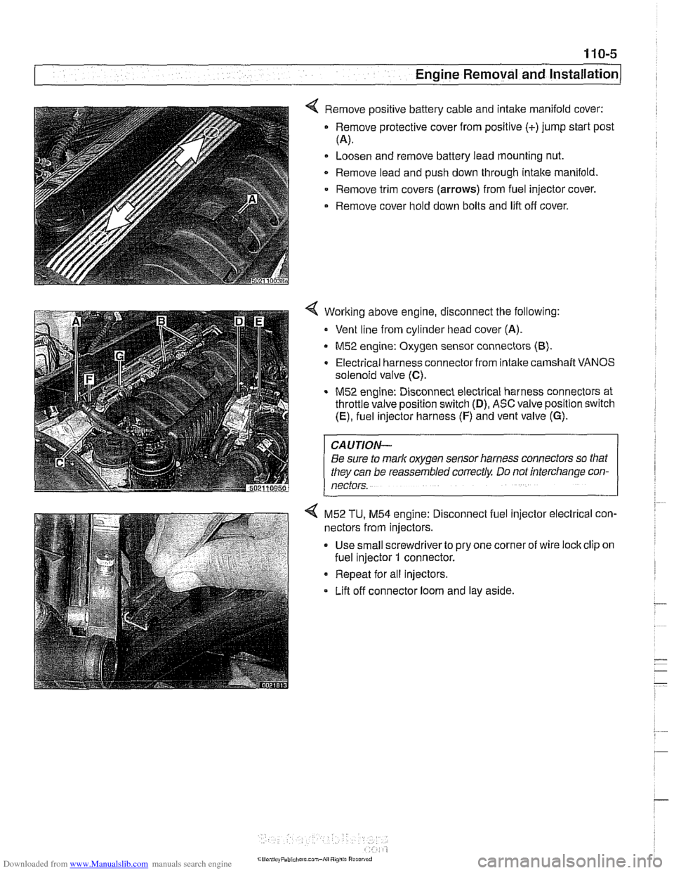
< Remove positive battery cable and intake manifold cover:
Remove protective cover from positive (+)jump start post
(4.
Loosen and remove battery lead mounting nut.
Remove lead and push down through intake manifold
Remove trim covers
(arrows) from fuel injector cover.
Remove cover hold down bolts and lift off cover.
Working above engine, disconnect the following:
Vent line from cylinder head cover (A).
M52 engine: Oxygen sensor connectors (8).
Electrical harness connector from intalte camshaft VANOS
solenoid valve
(C).
M52 engine: Disconnect electrical harness connectors at
throttle valve position switch
(D), ASC valve position switch
(E), fuel injector harness (F) and vent valve (G).
CAUTION-
Be sure to mark oxygen sensor harness connectors so that
they can be reassembled correctly Do not interchange con-
nectors.
4 M52 TU, M54 engine: Disconnect fuel injector electrical con-
nectors from injectors.
Use small screwdriverto pry one corner of wire lock clip on
fuel injector
1 connector.
Repeat for all injectors.
Lifl off connector loom and lay aside.
Page 152 of 1002
Downloaded from www.Manualslib.com manuals search engine
Cylinder Head Removal and Installation
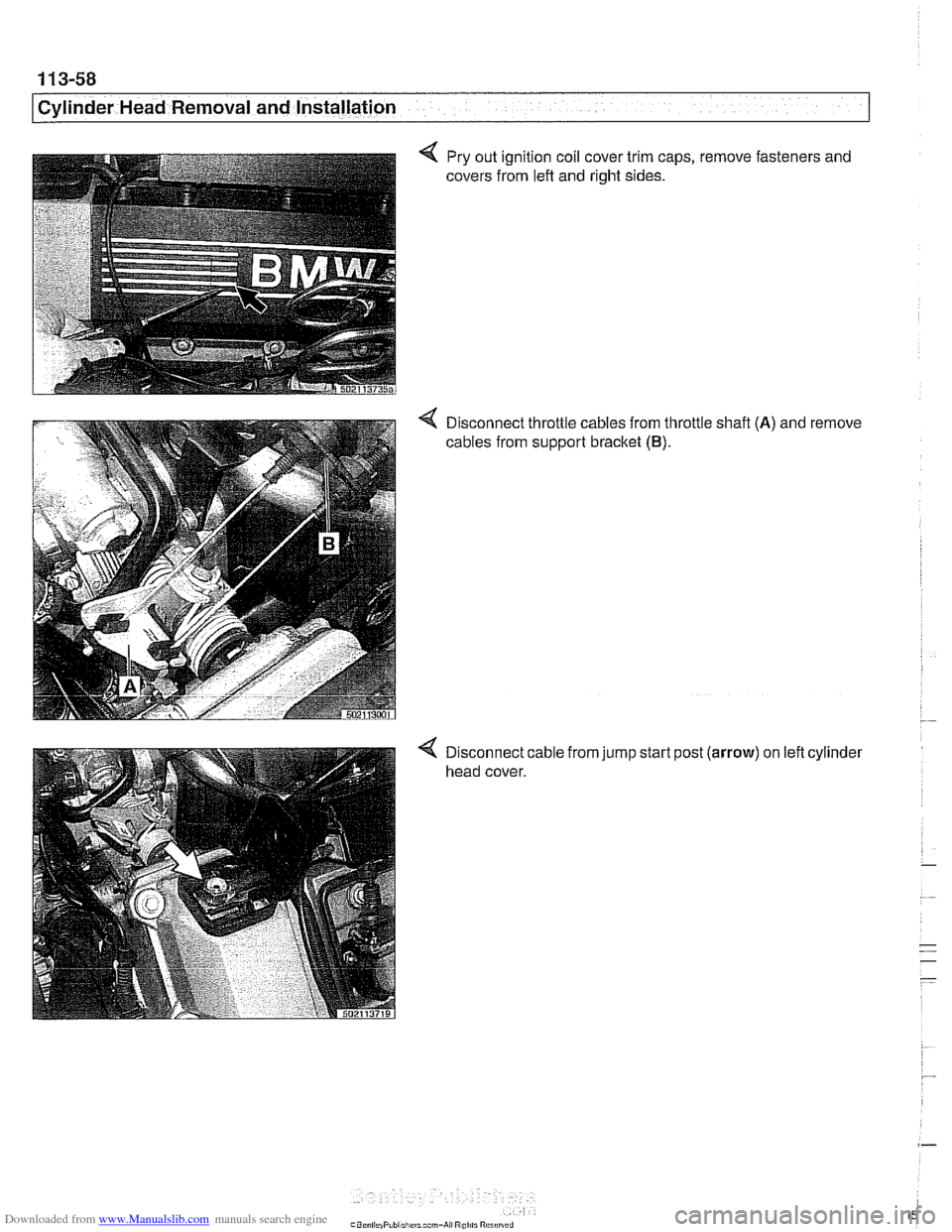
Pry out ignition coil cover trim caps,
covers from lefl and right sides. remove fasteners
and
< Disconnect throttle cables from throttle shafl (A) and remove
cables from support bracket
(B).
< Disconnect cable from jump start post (arrow) on left cylinder
head cover.
Page 185 of 1002
Downloaded from www.Manualslib.com manuals search engine
11 6-9
Cvlinder Head and valvetrain1
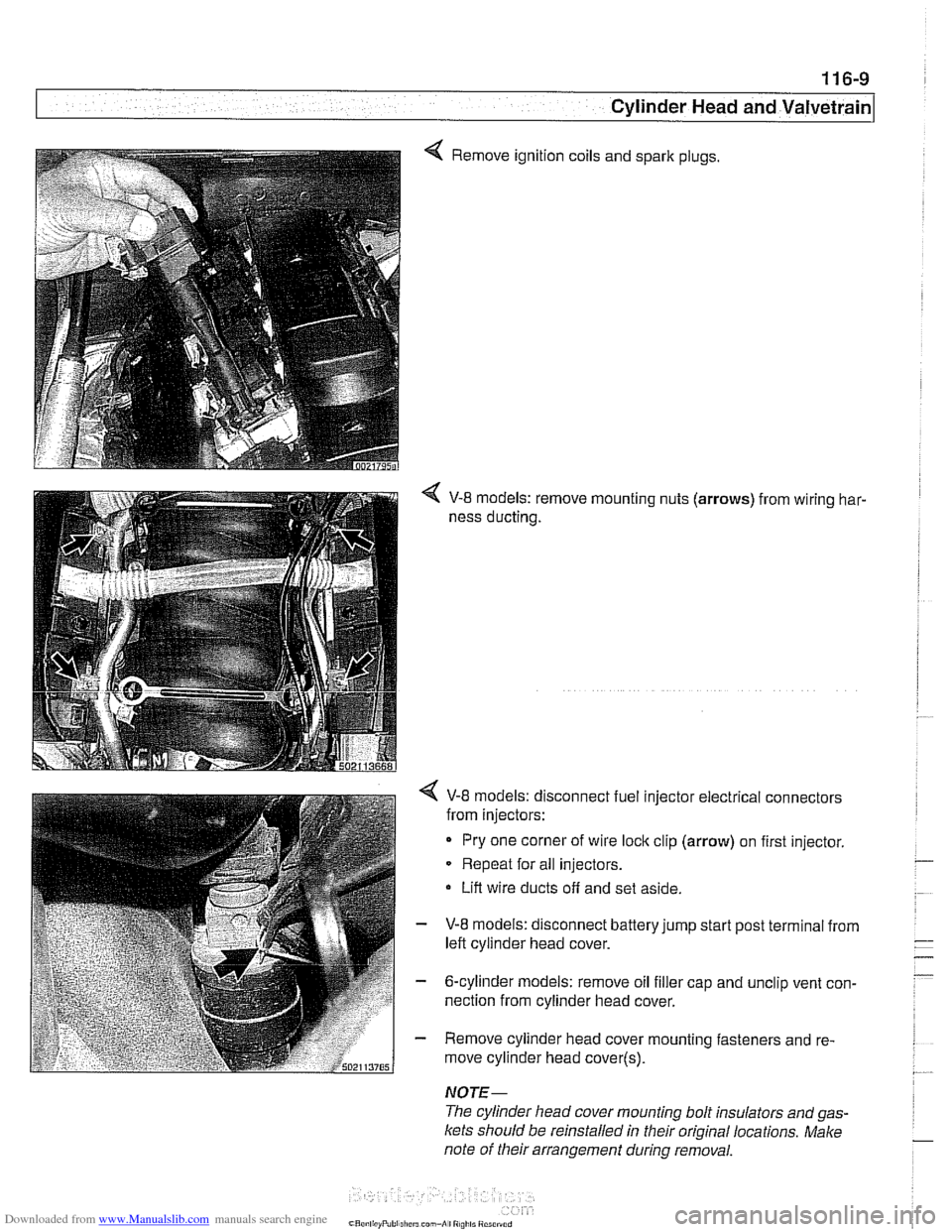
4 Remove ignition coils and spark plugs.
V-8 models: remove mounting nuts (arrows) from wiring har-
ness ducting.
< V-8 models: disconnect fuel injector electrical connectors
from injectors:
Pry one corner of wire
loclc clip (arrow) on first injector.
Repeat for all injectors.
Lift wire ducts off and set aside.
- V-8 models: disconnect battery jump start post terminal from
left cylinder head cover.
- 6-cylinder models: remove oil filler cap and unclip vent con-
nection from cylinder head cover.
- Remove cylinder head cover mounting fasteners and re-
move cylinder head cover(~).
NOTE-
The cylinder head cover mounting bolt insulators and gas-
Icets should be reinstalled in their original locations. Make
note of their arrangement
during removal.
Page 325 of 1002
Downloaded from www.Manualslib.com manuals search engine
. .- -
L
- --
- - -. - -- Lubrication ~~stern
- Remove pressure gauge and reinstall pressure switch with
new sealing washer.
Tightening torque
Oil pressure switch to oil filter housing 27 Nm (20 ft-lb)
If testing shows low oil pressure, one or more of the following
conditions may be indicated:
Worn or faulty oil pump or faulty pump pressure relief valve
Worn or damaged engine bearings
Severe engine wear
Any of these conditions indicate the need for major repairs.
Oil pressure warning system, testing
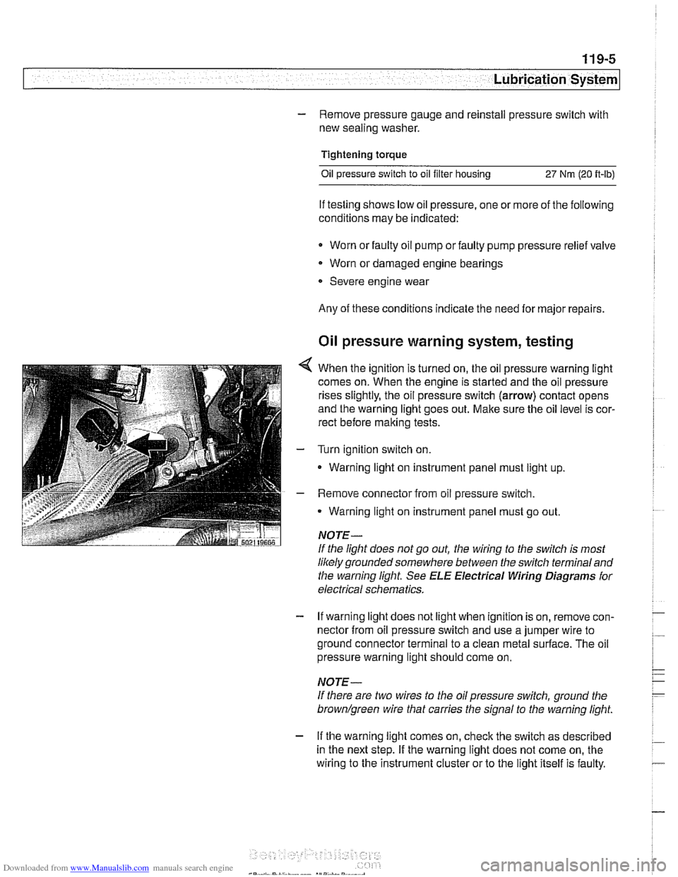
4 When the ignition is turned on, the oil pressure warning light
comes on. When the engine is started and the oil pressure
rises slightly, the oil pressure switch (arrow) contact opens
and the warning light goes out. Make sure the oil level is cor-
rect before making tests.
- Turn ignition switch on.
- Warning light on instrument panel must light up
- Remove connector from oil pressure switch.
Warning light on instrument panel must go out.
NOTE-
If the light does not go out, the wiring to the switch is most
likely grounded somewhere between the switch terminaland
the warning light See
ELE Electrical Wiring Diagrams for
electrical schematics.
- If warning light does not light when ignition is on, remove con-
nector from oil pressure switch and use a jumper wire to
ground connector terminal to a clean metal surface. The oil
pressure warning light should come on.
NOTE-
If there are two wires to the oil pressure switch, ground the
brown/green wire that carries the signal to the warning light.
- If the warning light comes on, check the switch as described
in the next step. If the warning light does not come on, the
wiring to the instrument cluster or to the light itself is faulty.
Page 359 of 1002
Downloaded from www.Manualslib.com manuals search engine
Ignition System
- Turn ignition on and check for battery voltage,
If battery voltage is not present,
checlt wire between termi-
nal
15 and the unloader relay. See ELE Electrical Wiring
Diagrams.
- Turn ignition off.
Remove coil and inspect coil housing for hairline
cracks or
leaking casting material. Replace any
cracked or leaking coil.
NOTE-
A leaky coil may indicate a faulty Engine Control Module
(ECM). Check ECM before installing a new coil.
CAUTION-
Note location of coilground straps before coil removal; rein-
stall in the same location.
Use a multimeter to test:
Coil primary resistance at coil terminals.
Sparlt plug connector resistance.
* Compare results to specification in Table c. lgnition coil
resistance.
Table c. Ignition coil resistance
Coil secondary
resistance
Spark plug connector:
Bosch 1 .O I( ohm t 20%
1.8 ir ohm t 20%
Component
Co~l prlmary
resistance
- Replace ignition coil or sparlt plug connector if resistance
readings do not meet specifications.
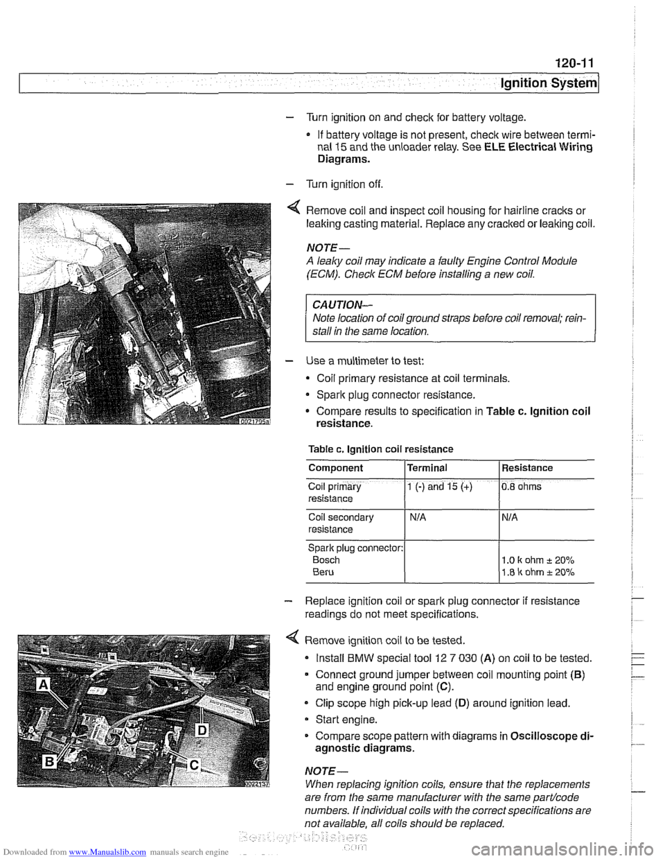
4 Remove ignition coil to be tested.
Install
BMW special tool 12 7 030 (A) on coil to be tested.
Connect ground jumper between coil mounting point
(B)
and engine ground point (C).
Clip scope high pick-up lead (D) around ignition lead.
Start engine.
Compare scope pattern with diagrams in Oscilloscope
di-
agnostic diagrams.
NOTE-
When replacing ignition coils, ensure that the replacements
Terminal
1 (-) and 15 (+)
are
from the same manufacturer with the same partlcode
numbers. If individual coils with the correct specifications are
not available. all coils should be
re~laced.
Resistance
0.8 ohms
Page 380 of 1002
Downloaded from www.Manualslib.com manuals search engine
- -
/Battery, Starter, Alternator -- - -. - --I
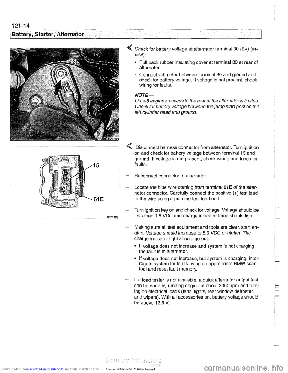
< Check for battery voltage at alternator terminal 30 (B+) (ar-
row):
Pull back rubber insulating cover at terminal 30 at rear of
alternator.
Connect voltmeter between terminal 30 and ground and
check for battery voltage.
If voltage is not present, check
wiring for faults.
NOTE-
On V-8 engines, access to the rear of the alternator is limited.
Check for battery voltage between the jump start post on the
left cylinder head and ground.
r Disconnect harness connector from alternator. Turn ianition
on and check for battery voltage between terminal
lgand
ground. If voltage is not present, check wiring and fuses for
faults.
Reconnect connector to alternator.
Locate the blue wire coming from terminal
61E of the alter-
nator connector. Carefully connect the positive
(+) test lead
to the wire using a piercing test lead end.
Turn ignition key on and check for voltage. Voltage should be
less than 1.5 VDC and charge indicator lamp should light.
- Making sure all test equipment and tools are clear, start en-
gine. Voltage should increase to
8.0 VDC or higher. The
charge indicator light should go out.
If voltage does not increase and system is not charging,
the fault is in alternator.
- If voltage does not increase, but system is charging, inter- - roaate svstem for faults usina an appropriate BMW scan - .. . tool and'reset fault memory.
- If a load tester is not available, a quick alternator output test
can be done by running engine at about 2000 rpm and turn-
- -
ing on electrical loads (fans, lights, rear window defroster, -
- and wipers). With all accessories on, battery voltage should
be above 12.6
V.
Page 382 of 1002
Downloaded from www.Manualslib.com manuals search engine
121-16
Battery, Starter, Alternator
- installation is reverse of removal.
Tightening torques Belt tensloner to engine block
M8 (8.8 grade) 22
Nm (16 ft-ib)
Fan clutch to coolant pump
with BMW special tool 11
5 040 30 Nm (22
ft-lb)
without BMW special tool
11 5 040 40 Nm
(29 ft-ib)
Pulley to alternator 70
Nm (44 ft-lb)
Terminal 30
(B+) wire to alternator (M8) 13 Nm (10 ft-ib)
Alternator, removing and installing
(M62 engine, air cooled)
A replacement alternator should have the same rating as the
original. Alternator manufacturer and ampere rating are nor-
mally
marked on the alternator housing.
- Disconnect negative (-) battery cable.
CAUTION-
Prior to disconnecting the battery, read the battery discon-
nection cautions
001 General Warnings and Cautions.
- Remove cooling fan and alternator drive belt. See 020 Main-
tenance.
- Pry out trim caps and remove fasteners from plastic cover on
left head. Lift off cover.
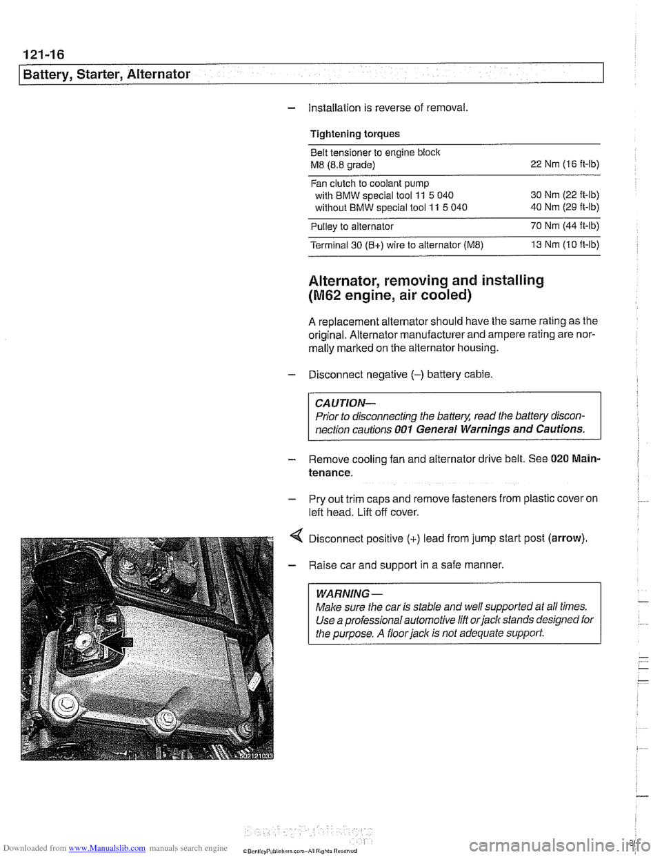
Disconnect positive
(+) lead from jump start post (arrow).
Raise car and support in a safe manner.
WARNING-
Make sure the car is stable and well supported at aN times.
Use a professional automotive lift
orjack stands designed for
the purpose.
A floorjack is not adequate support.