Intake hoses BMW 528i 1998 E39 Workshop Manual
[x] Cancel search | Manufacturer: BMW, Model Year: 1998, Model line: 528i, Model: BMW 528i 1998 E39Pages: 1002
Page 75 of 1002
Downloaded from www.Manualslib.com manuals search engine
110-3
Engine Removal and lnstallationl
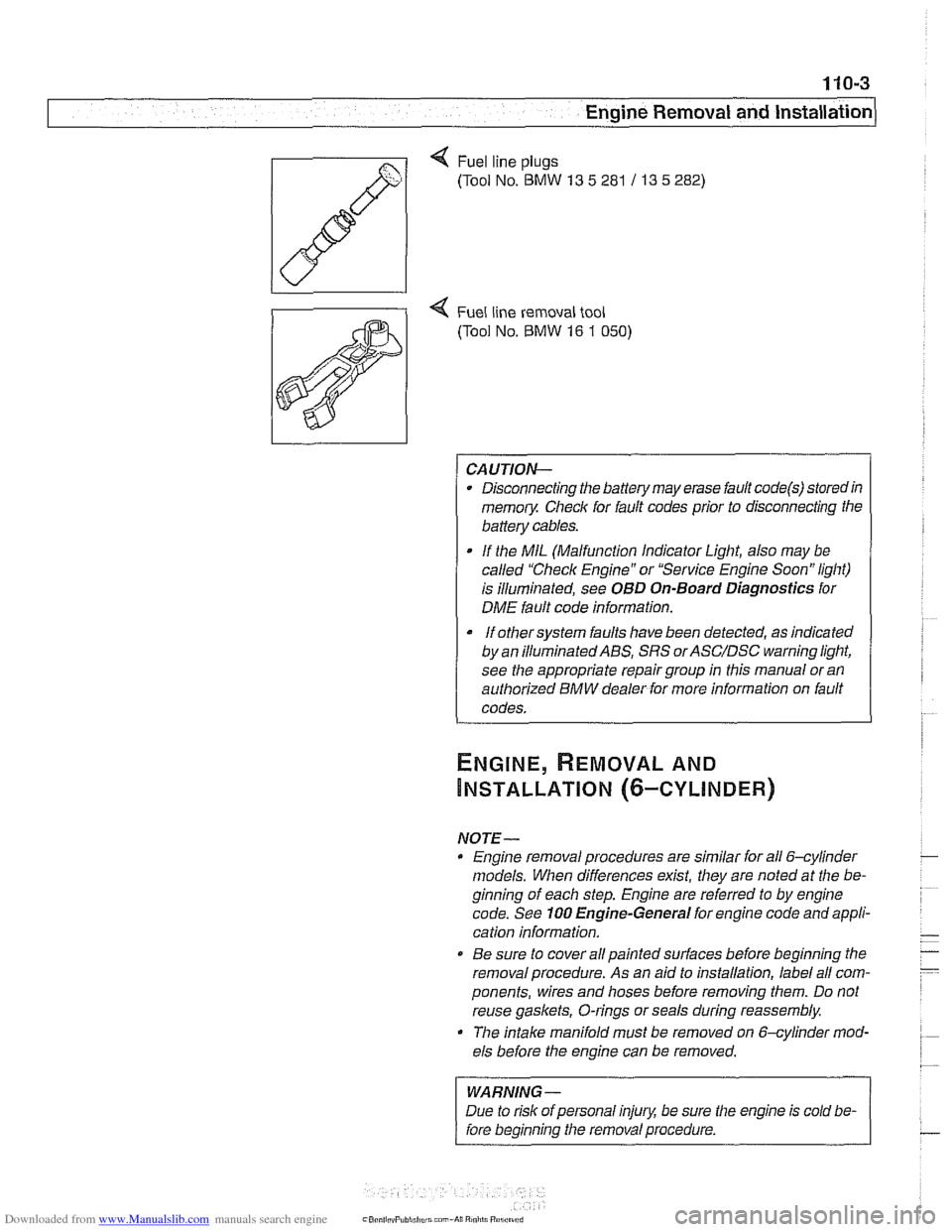
Q Fuel line plugs
(Tool No.
BMW 13 5 281 / 13 5 282)
4 Fuel line removal tool
(Tool No.
BMW 16 1 050)
CAUTION-
Disconnecting the battery may erase fault code@) storedin
memoiy Check for fault codes prior to disconnecting the
battery cables.
If the MIL (Malfunction Indicator Light, also may be
called "Check Engine" or "Service Engine Soon" light)
is illuminated, see
OBD On-Board Diagnostics for
DME fault code information.
It orhersysrem faults have been detected, as indicated I
by an ~llum~nated ABS, SRS orASC/DSC ~arning light,
see the appropriate repair group in this manual or an
authorized BMW dealer for more information on fault
codes.
NOTE- Engine removal procedures are similar for all 6-cylinder
models. When differences
exist, they are noted at the be-
ginning of each step. Engine are referred to by engine
code. See
100 Engine-General for engine code and appli-
cation information.
@ Be sure to cover all painted surfaces before beginning the
removal procedure. As an aid to installation, label all com-
ponents, wires and hoses before removing them. Do not
reuse
gaskets, O-rings or seals during reassembly.
The
intake manifold must be removed on &cylinder mod-
els before the engine can be removed.
WARNING-
Due to risk of personal injury, be sure the engine is cold be-
fore beginning the removal procedure.
Page 79 of 1002
Downloaded from www.Manualslib.com manuals search engine
Engine Removal and lnstallationl
NOTE-
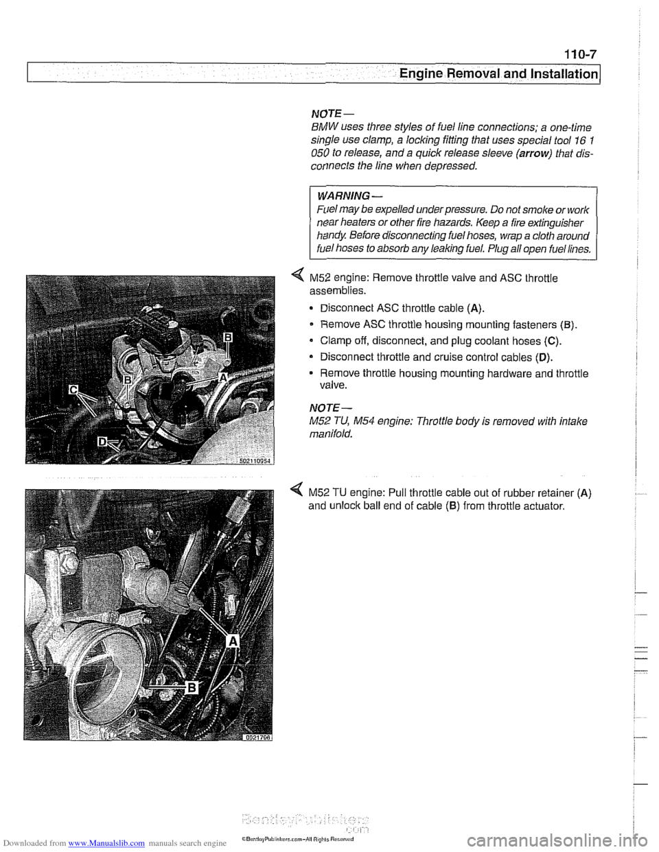
BMW uses three styles of fuel line connections; a one-time
single use clamp, a locking fitting that uses special tool
16 1
050 to release, and a quick release sleeve (arrow) that dis-
connects the line when depressed.
WARNING-
Fuel may be expelled under pressure. Do not smoke or work
near heaters or other fire hazards. Keep a fire extinguisher
handy Before disconnecting fuel hoses, wrap a cloth around
fuel hoses to absorb any leaking fuel. Plug all
oDen fuel lines.
< M52 engine: Remove throttle valve and ASC throttle
assemblies.
Disconnect ASC throttle cable
(A).
Remove ASC throttle housing mounting fasteners (El).
Clamp off, disconnect, and plug coolant hoses (C).
Disconnect throttle and cruise control cables (D).
Remove throttle housing mounting hardware and throttle
valve.
NOTE-
M52 TU, M54 engine: Throttle body is removed with intake
manifold.
< M52 TU engine: Pull throttle cable out of rubber retainer (A)
and unloclc ball end of cable (6) from throttle actuator.
Page 82 of 1002
Downloaded from www.Manualslib.com manuals search engine
.-
-6val and Installation -
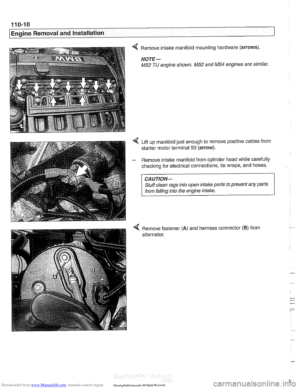
< Remove intake manifold mounting hardware (arrows).
NOTE-
M52 TU engine shown. M52 and M54 engines are similar.
Liit up manifold just enough to remove positive cables from
starter motor terminal
50 (arrow).
- Remove intake manifold from cylinder head while carefully
checking for electrical connections, tie wraps, and hoses.
CAUTION-
Stuff clean rags into open intake ports to prevent any parts
from falling into the engine intake.
4 Remove fastener (A) and harness connector (B) from
alternator.
Page 88 of 1002
Downloaded from www.Manualslib.com manuals search engine
110-16
Engine Removal and Installation
ENGINE, REMOVAL AND
INSTALLATION (V-8 MODELS)
NOTE-
Engine removal procedures are similar for all V-8 models.
When differences exist, they are noted at the beginning of
each step. Engine are referred to by engine code. If neces-
sary, See
100 Engine-General for engine code andappli-
cation information.
Be sure to cover all painted surfaces before beginning the
removal procedure. As an aid to installation, label all com-
ponents, wires and hoses before removing them. Do not
reuse gaskets, O-rings or seals during reassembly
WARNING
-
Due to risk ofpersonal injury, be sure the engine is cold be-
fore beginning the
removal procedure.
- Disconnect negative (-) cable from battery.
Prior to disconnecting the battery, read the battery discon-
nection cautions given in
001 General Cautions and
Warnings.
- Remove engine hood or place hood in service position. See
410 Fenders, Engine Hood.
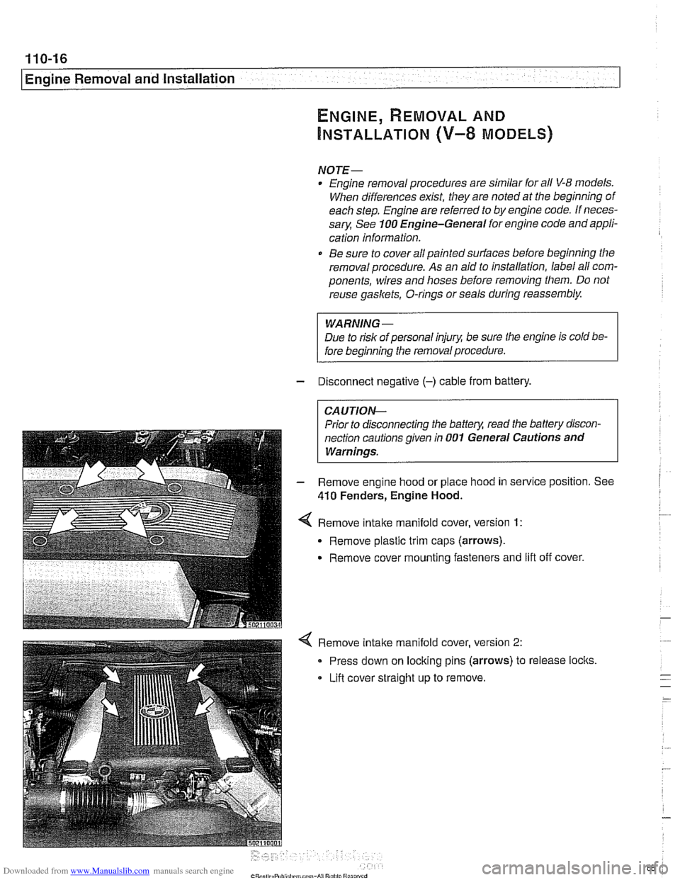
Remove
intake manifold cover, version 1:
Remove plastic trim caps (arrows).
Remove cover mounting fasteners and
lift off cover.
Remove intake manifold cover, version
2:
Press down on locking pins (arrows) to release locks
Lifl cover straight
up to remove.
Page 90 of 1002
Downloaded from www.Manualslib.com manuals search engine
I Engine Removal and Installation
WARNING -
Use extreme caution when draining and disposing of engine
coolant. Coolant is poisonous andlethal to humans andpets.
Pets are attracted to coolant because of its sweet smell and
taste. Seek medical attention immediately if coolant is ingest-
---
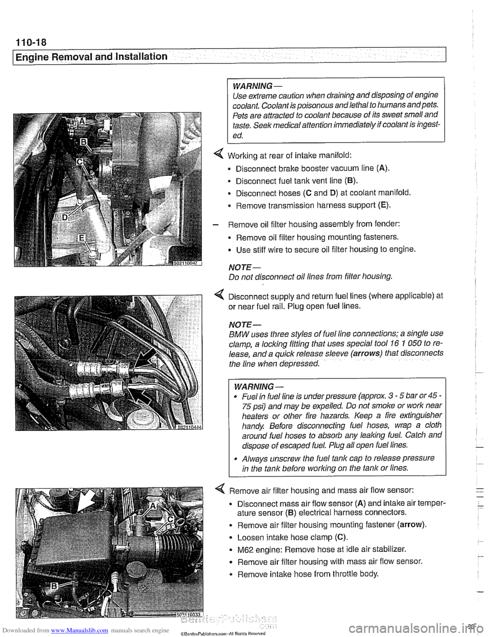
Working at rear of intake manifold:
Disconnect brake booster vacuum line (A).
Disconnect fuel tank vent line
(6).
Disconnect hoses (C and D) at coolant manifold
- Remove transmission harness support (E).
- Remove oil filter housing assembly from fender:
- Remove oil filter housing mounting fasteners.
Use stiff wire to secure oil filter housing to engine.
NOTE-
Do not disconnect oil lines from filter housing.
4 Disconnect supply and return fuel lines (where applicable) at
or near fuel rail. Plug open fuel lines.
NOTE-
BMW uses three styles of fuel line connections; a slngle use
clamp, a locking fitting that uses special tool
16 7 050 to re-
lease, and a
quiclc release sleeve (arrows) that disconnects
the line when depressed.
WARNING-
Fuel In fuel line is under pressure (approx. 3 - 5 bar or45 -
75 psi) and may be expelled. Do not smoke or worlc near
heaters or other fire hazards. Keep a fire extinguisher
handy. Before disconnecting fuel hoses, wrap a cloth
around fuel hoses to absorb any lealcing fuel. Catch and
dispose of escaped fuel. Plug all open fuel lines.
. Always unscrew the fuel tank cap to release pressure
in the tank before worlcing on the tank or lines.
< Remove air filter housing and mass air flow sensor:
Disconnect mass air flow sensor (A) and
intalte air temper-
ature sensor
(6) electrical harness connectors.
. Remove air filter housing mounting fastener (arrow).
Loosen intake hose clamp (C).
M62 engine: Remove hose at idle air stabilizer.
Remove air filter housing with mass air flow sensor.
Remove intalte hose from throttle body.
Page 105 of 1002
Downloaded from www.Manualslib.com manuals search engine
..
Cylinder Head Removal and Installation 1
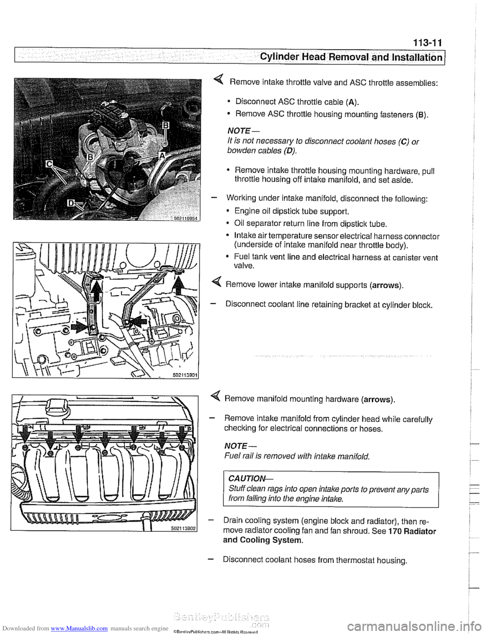
< Remove intake throttle valve and ASC throttle assemblies:
Disconnect ASC throttle cable
(A).
- Remove ASC throttle housing mounting fasteners (B).
NOTE-
It is not necessary to disconnect coolant hoses (C) 01
bowden cables (D).
Remove intake throttle housing mounting hardware, pull
throttle housing off
intake manifold, and set aside.
- Working under intake manifold, disconnect the following:
Engine oil dipstick tube support.
Oil separator return line from dipstick tube.
Intake air temperature sensor electrical harness connector
(underside of intake manifold near throttle body).
* Fuel tank vent line and electrical harness at canister vent
valve.
Remove lower intake manifold supports (arrows).
- Disconnect coolant line retaining bracket at cylinder block.
4 Remove manifold mounting hardware (arrows).
- Remove intake manifold from cylinder head while carefully
checking for electrical connections or hoses.
NOTE-
Fuel rail is removed with intake manifold,
CAUTIOI\C
Stuff clean rags into open intake ports to prevent any parts
from falling into
Nie engine intake.
- Drain cooling system (engine block and radiator), then re-
move radiator cooling fan and fan shroud. See
170 Radiator
and Cooling System.
- Disconnect coolant hoses from thermostat housing.
Page 109 of 1002
Downloaded from www.Manualslib.com manuals search engine
Cylinder Head Removal and Installation / -
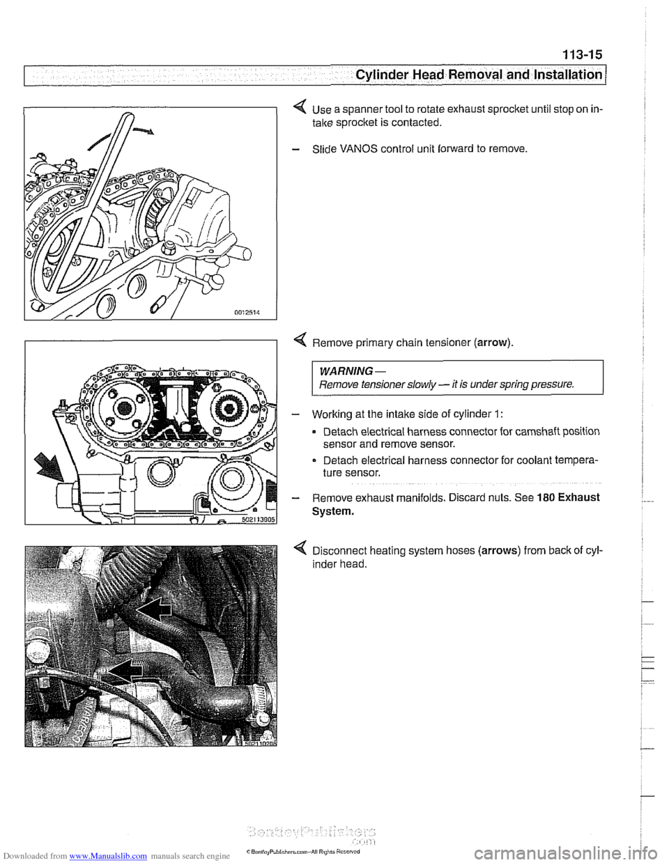
< Use a spanner tool to rotate exhaust sprocket until stop on in-
take sprocket is contacted.
- Slide VANOS control unit forward to remove
Remove primary chain tensioner (arrow)
WARNING -
Remove tensioner slowly - it is under spring pressure. I
- Working at the intake side of cylinder 1 :
Detach electrical harness connector for camshaft position
sensor and remove sensor.
Detach electrical harness connector for coolant tempera-
ture sensor.
- Remove exhaust manifolds. D~scard nuts. See 180 Exhaust
System.
Disconnect heating system hoses (arrows) from back of cyl-
inder head.
Page 118 of 1002
Downloaded from www.Manualslib.com manuals search engine
. .- -
Cylinder Head Removal and Installation
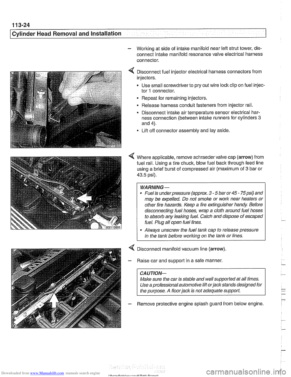
- Working at side of intake manifold near left strut tower, dis-
connect intake manifold resonance valve electrical harness
connector.
4 Disconnect fuel injector electrical harness connectors from
injectors.
- Use small screwdriver to pry out wire lock clip on fuel injec-
tor
1 connector.
Repeat for remaining injectors.
Release harness conduit fasteners from injector rail.
- Disconnect intake air temperature sensor electrical har-
ness connection (between intake runners for cylinders
3
and 4).
Lift off connector assembly and lay aside.
4 Where applicable, remove schraeder valve cap (arrow) from
fuel
ra~l. Using a tire chuck, blow fuel back through feed line
using a brief burst of compressed air (maximum of
3 bar or
43.5 psi).
WARNING-
Fuel is underpressure (approx. 3 - 5 bar or 45 - 75psi) and
may be expelled. Do not smoke or
work near heaters or
other fire hazards. Keep a fire extinguisher handy Before
d~sconnecting fuel hoses, wrap a cloth around fuel hoses
to absorb any leaking fuel. Catch and
dfspose of escaped
fuel. Plug all open fuel lines.
Always unscrew the fuel tank cap to release pressure
I in the tank before working on the tank or lines.
Disconnect manifold vacuum line (arrow)
Raise car and support in a safe manner,
CAUTION-
Make sure the car is stable and well supported at all times.
Use a professional automotive lift
orjack stands designed for
the purpose. A
floorjack is not adequate support.
Remove protective engine splash guard from below engine.
Page 154 of 1002
Downloaded from www.Manualslib.com manuals search engine
1 13-60
Cylinder Head Removal and Installation
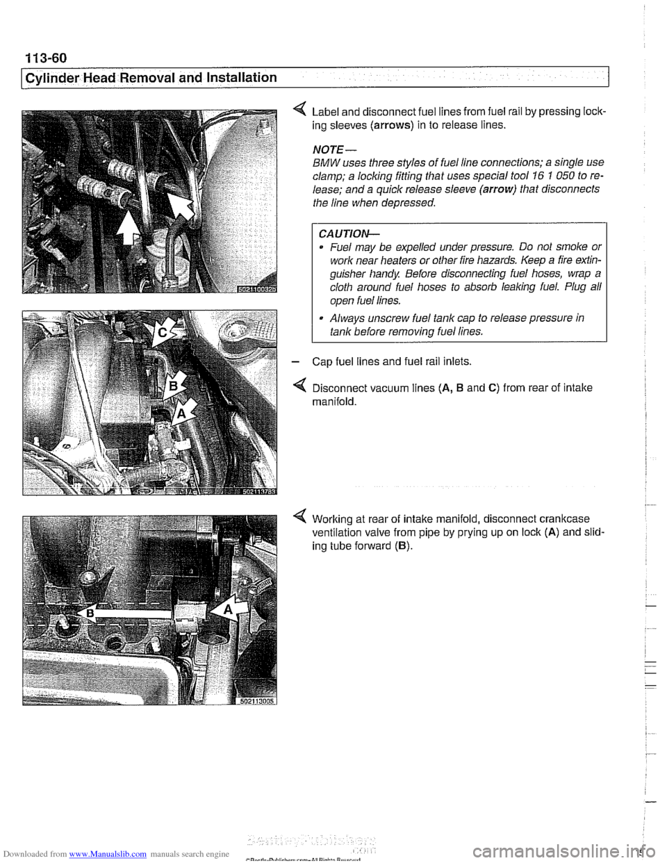
Label and disconnect fuel lines from fuel rail by pressing lock-
ing sleeves
(arrows) in to release lines.
NOTE-
BMW uses three styles of fuel line connections; a single use
clamp; a locking fitting that uses special tool
16 1 050 to re-
lease; and a quick release sleeve
(arrow) that disconnects
the line when depressed.
CAUTION-
Fuel may be expelled under pressure. Do not smoke or
work near heaters or other fire hazards. Keep a fire
exfin-
guisher handy Before disconnecting fuel hoses, wrap a
cloth around fuel hoses to absorb
leaking fuel. Plug all
I ooen fuel lines. I
Always unscrew fuel tank cap to release pressure in
tank before
removinq fuel lines.
Cap fuel lines and fuel rail inlets.
Disconnect vacuum lines
(A, B and C) from rear of intake
manifold.
Working at rear of intake manifold, disconnect crankcase
ventilation valve from pipe by prying up on lock
(A) and slid-
ing tube forward
(B).
Page 155 of 1002
Downloaded from www.Manualslib.com manuals search engine
11 3-61
Cylinder Head Removal and installation I
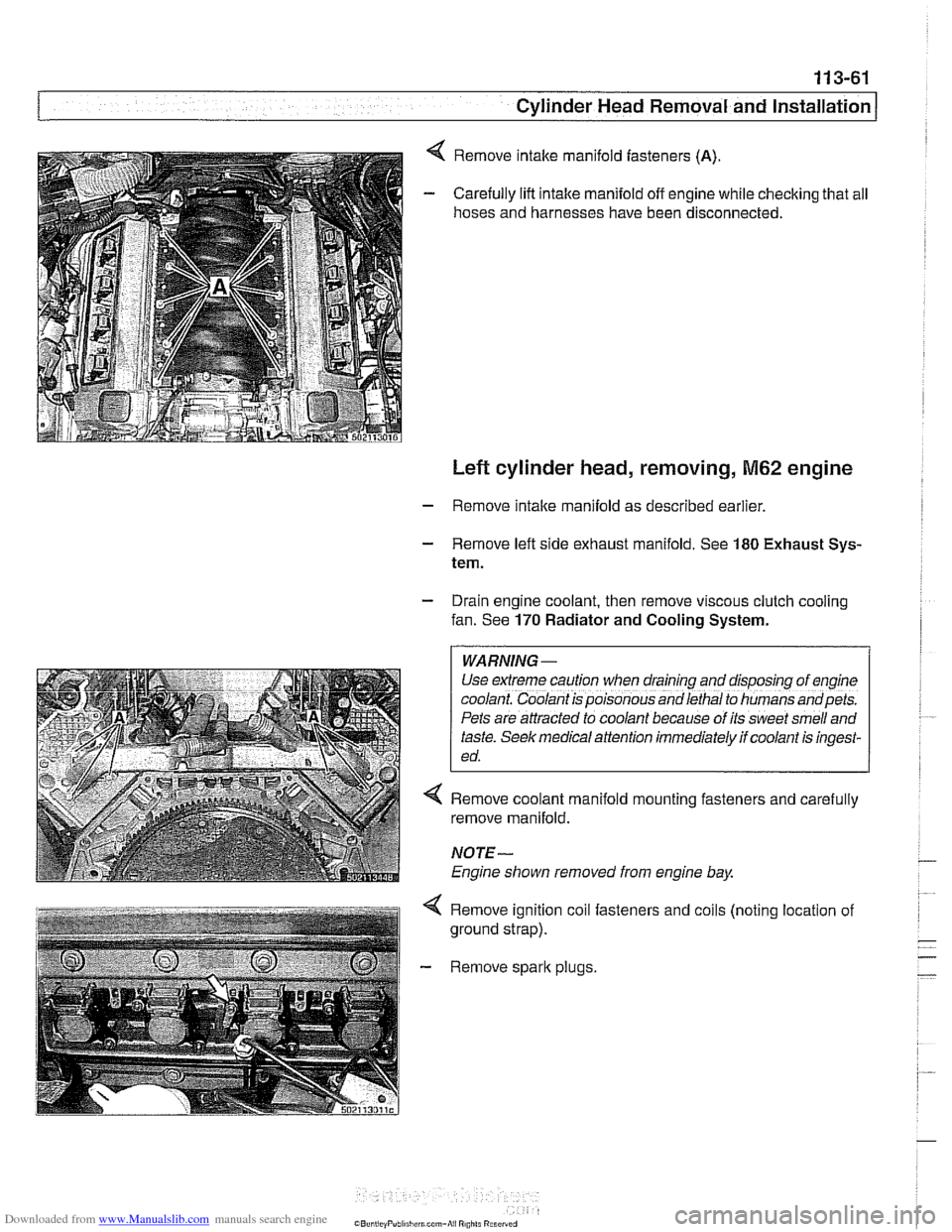
Remove intake manifold fasteners (A).
Carefully lift intake manifold off engine while checking that all
hoses and harnesses have been disconnected.
Left cylinder head, removing, M62 engine
- Remove intake manifold as described earlier
- Remove left side exhaust manifold. See 180 Exhaust Sys-
tem.
- Drain engine coolant, then remove viscous clutch cooling
fan. See
170 Radiator and Cooling System.
WARNING -
Use extreme caution when draining and disposfng of eng~ne
coolant. Coolant is poisonous and lethal to humans andpets.
Pets are attracted to coolant because of its sweet smell and
taste.
Seek med~cal attention immediately if coolant is ingest-
ed.
4 Remove coolant manifold mounting fasteners and carefully
remove manifold.
NOTE-
Engine shown removed from engine bay
4 Remove ignition coil fasteners and coils (noting location of
ground strap).
- Remove spark plugs.