Ignition switch BMW 528i 1998 E39 User Guide
[x] Cancel search | Manufacturer: BMW, Model Year: 1998, Model line: 528i, Model: BMW 528i 1998 E39Pages: 1002
Page 369 of 1002
Downloaded from www.Manualslib.com manuals search engine
Battery, Starter, ~lternatorl
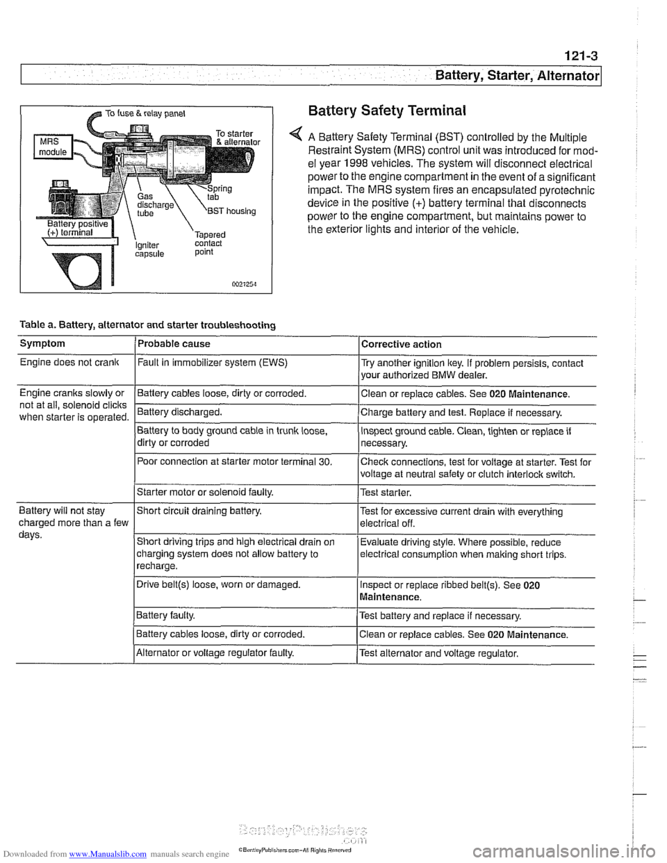
@ TO fuse & relay panel Battery Safety Terminal
A Battery Safety Terminal (BST) controlled by the Multiple
Restraint System (MRS) control unit was introduced for mod-
el year 1998
vehicles. The system will disconnect electrical
power to the engine compartment
in the event of a significant
impact. The MRS system fires an encapsulated pyrotechnic
device
in the positive (+) battery terminal that disconnects
power to the engine compartment, but maintains power to
the exterior lights and interior of the vehicle.
point
002125~1
Table a. Battery, alternator and starter troubleshooting
1-
/Starter motor or solenoid faulty. l~est starter.
Symptom
Engine does not crank
Engine cranks slowly or
not at all, solenoid
clicits
when starter is operated.
I I
Battery will not stay IShort circuit draining battery. l~est for excessive current drain with everything
Probable cause
Fault
in immobilizer system (EWS)
-Clean Battery cables loose, dirty or corroded.
Battery discharged.
Battery to body ground cable in trunk
loose,
dirty or corroded
Poor connection at starter motor terminal
30.
Corrective action
Try another ignition key. If problem persists, contact
your authorized BMW dealer.
or replace cables. See 020
~aintenance.
Charge battery and test. Replace if necessary.
inspect ground cable. Clean, tighten or replace if
necessary.
Checlc connections, test for voltage at starter. Test for
voltage at neutral safety or clutch
interloclc switch.
charged more than a few
days.
I~atter~ faulty. /Test battery and replace if necessary.
Short driving trips and high electrical drain
on
charging system does not allow battery to
recharge.
. I
I Battery cables loose, dirty or corroded. Iclean or replace cables. See 020 Maintenance.
Evaluate driving
style. Where possible, reduce
electrical
consumption when malting short trips.
Drive
belt@) loose, worn or damaged.
IAlternator or voltage regulator faulty. /Test alternator and voltage regulator.
Inspect
or replace ribbed
belt@). See 020
Maintenance.
Page 373 of 1002
Downloaded from www.Manualslib.com manuals search engine
Battery, Starter, ~lternatorl
WARNING-
Always wear protective goggles and clothing when perform-
ing a load test.
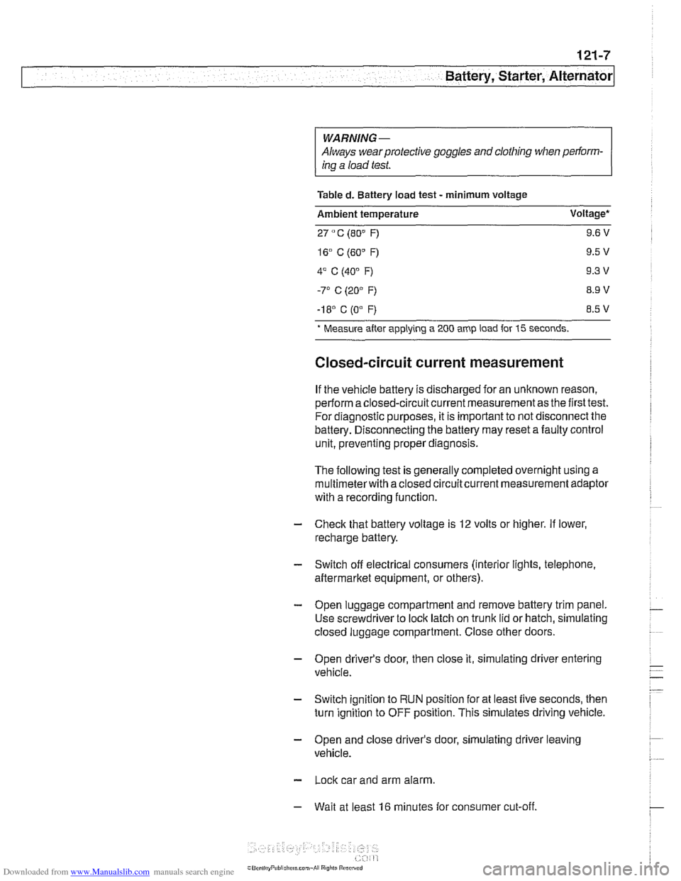
Table
d. Battery load test - minimum voltage
Ambient temperature Voltage*
27
" C (80" F) 9.6 V
-I 8' C (0"
F) 8.5 V
* Measure
after applying a 200 amp load for 15 seconds.
Closed-circuit current measurement
If the vehicle battery is discharged for an unknown reason,
perform a closed-circuit current measurement as the first test.
For diagnostic purposes, it is important to not disconnect the
battery. Disconnecting the battery may reset a faulty control
unit, preventing proper diagnosis.
The following test is generally completed overnight using a
multimeterwith a closed circuitcurrent measurement adaptor
with a recording function
- Check that battery voltage is 12 volts or higher. If lower,
recharge battery.
- Switch off electrical consumers (interior lights, telephone,
aftermarket equipment, or others).
- Open luggage compartment and remove battery trim panel.
Use screwdriver to lock latch on trunk lid or hatch, simulating
closed luggage compartment. Close other doors.
- Open driver's door, then close it, simulating driver entering
vehicle.
- Switch ignition to RUN position for at least five seconds, then
turn ignition to OFF position. This simulates driving vehicle.
- Open and close driver's door, simulating driver leaving
vehicle.
- Lock car and arm alarm.
- Wait at least 16 minutes for consumer cut-off.
Page 377 of 1002
Downloaded from www.Manualslib.com manuals search engine
121-11
Battery, Starter, ~lternatorl
Alternator 1997 - 98 5281 1997 540i
/-- -----,
I'
-----------
F15 / 7.5A/ :
&.. .... , 30 1 Xi0015
Battery
Hol in run 61 E (D+) Alternator
and stsrt
lBL
(Generator)
1 .--------,charge , . I , indicator I xGoli i
I <"9,7,a,T
Alternator, basic
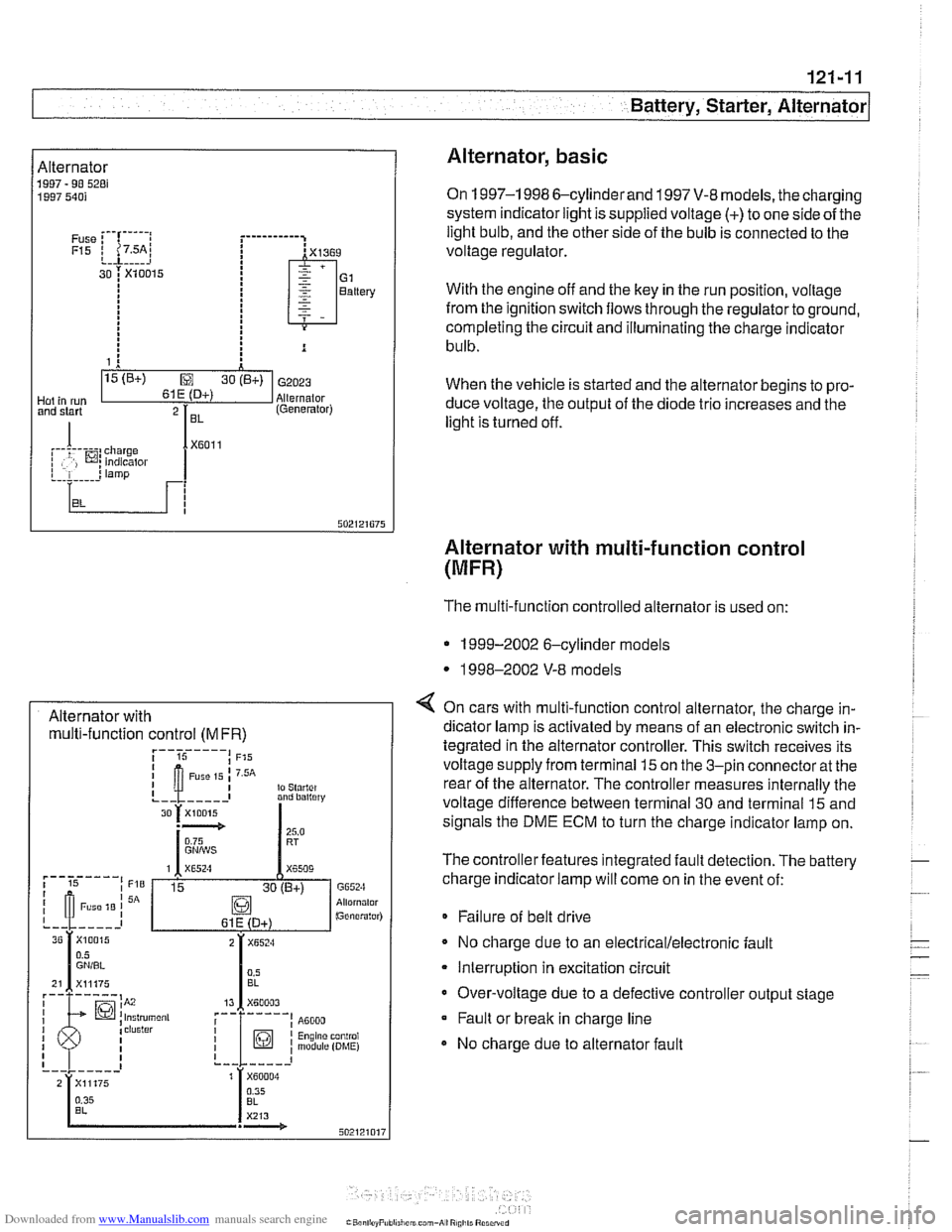
On 1997-1 998 6-cylinderand 1997 V-8 models, the charging
system indicator light is supplied voltage
(+) to one side of the
light bulb, and the other side of the bulb is connected to the
voltage regulator.
With the engine off and the key in the run position, voltage
from the ignition switch flows through the regulator to ground,
completing the circuit and illuminating the charge indicator
bulb.
When the vehicle is started and the alternator begins to pro-
duce voltage, the output of the diode trio increases and the
light is turned off.
Alternator with multi-function control
(MFR)
Alternator with multi-function control
(MFR)
The multi-function controlled alternator is used on:
* 1999-2002 6-cylinder models
* 1998-2002 V-8 models
4 On cars with multi-function control alternator, the charge in-
dicator lamp is activated by means of an electronic switch in-
tegrated in the alternator controller. This switch receives its
voltage supply from terminal
15 on the 3-pin connector at the
rear of the alternator. The controller measures internally the
voltage difference between terminal 30 and terminal
15 and
signals the DME ECM to turn the charge indicator lamp on.
The controller features integrated fault detection. The battery
charge indicator lamp will come on in the event of:
* Failure of belt drive
No charge due to an
electrical/electronic fault
Interruption in excitation circuit
Over-voltage due to a defective controller output stage Fault or break in charge line
No charge due to alternator fault
Page 385 of 1002
Downloaded from www.Manualslib.com manuals search engine
Battery, Starter, Alternator
- Installation is reverse of removal, noting the following:
Replace alternator rubber sealing O-ring.
* Fill and bleed cooling system as described in 170 Radiator
and Cooling System.
Tightening torques
Fan clutch to coolant pump
with
BMW special tool 11 5 040 30 Nm (22 ft-lb)
without
BMW special tool 11 5 040 40 Nm (29 ft-lb)
Terminal 30 (Bc) wire to alternator (ME) 13 Nm (10 ft-lb)
STARTER
Starter troubleshooting
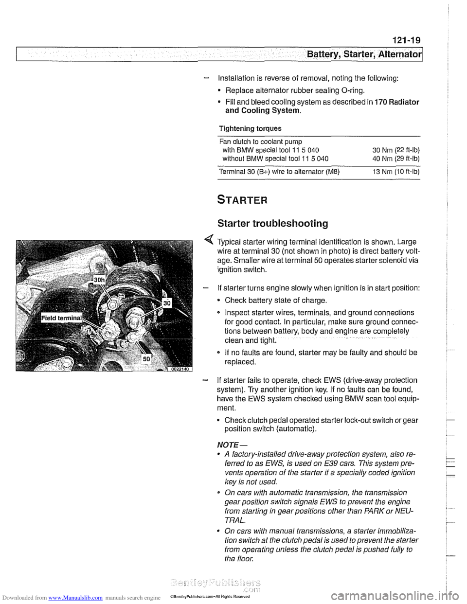
Typical starter wiring terminal identification is shown. Large
wire at terminal
30 (not shown in photo) is direct battery volt-
age. Smaller wire at terminal
50 operates starter solenoid via
ignition switch.
If starter turns engine slowly when ignition is in start position:
Check battery state of charge.
Inspect starter wires, terminals, and ground
connectlons
for good contact. In particular, make sure ground connec-
tions between battery, body and
englne are completely
clean and tight.
If no faults are found, starter may be faulty and should be
replaced.
- If starter fails to operate, check EWS (drive-away protection
system). Try another ignition key.
If no faults can be found,
have the EWS system checked using
BMW scan tool equip-
ment.
Checkclutch pedal operated
starter lock-out switch or gear
position switch (automatic).
NOTE-
* A factory-installed drive-away protection system, also re-
ferred to as
EWS, is used on E39 cars. This system pre-
vents operation of the starter if a specially coded ignition
key is not used.
On cars with automatic transmission, the transmission
gear position switch signals
EWS to prevent the engine
from starting in gear positions other than PARK or NEU-
TRAL.
On cars with manual transmissions, a starter immobiliza-
tion switch
at the clutch pedal is used to prevent the starter
from operating unless the clutch pedal is pushed fully to
the floor.
Page 386 of 1002
Downloaded from www.Manualslib.com manuals search engine
I Battery, Starter, Alternator
- Check for battery voltage at terminal 50 of starter motor with
key in start position. If voltage is not present, check wiring be-
tween ignition switch and starter terminal. Check the EWS
system and other inputs that disrupt terminal
56 to the start-
er. See ELE Electrical
Wiring Diagrams. If voltage is
present and no other visible wiring faults can be found, prob-
lem is most likely in starter motor.
Starter, removing and installing
(6-cylinder engine)
The starter is removed from below. Access to starter bolts is
difficult. Be sure to have the proper tools on hand before pro-
ceeding.
NOTE-
Access to the starter wiring is very limited. Forbetteraccess,
it may be necessary to remove the intake manifold.
- Disconnect negative (-) battery cable.
CAUTIOI\C
Prior to disconnecting the battern read the baltery discon-
nection cautions
in OOlGeneral Cautions and Warnings.
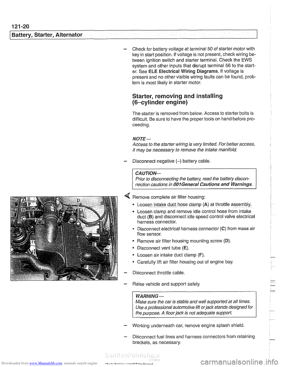
Remove complete air filter hous~ng:
Loosen intake duct hose clamp (A) at throttle assembly.
Loosen clamp and remove idle control hose from intake
duct
(B) and disconnect idle speed control valve electrical
harness connector.
Disconnect electrical harness connector
(C) from mass air
flow sensor.
Remove air filter housing mounting screw (D)
Disconnect vent tube
(E).
Loosen air intake duct clamp (F).
Carefully lift air filter housing out of engine bay.
Disconnect throttle cable.
Raise vehicle and support safely.
WARNING-
Make sure the car is stable and well supported at all times.
Use a professional automotive
lift orjack stands designed for
the purpose. A
floorjaclc is not adequate support
- Working underneath car, remove engine splash shield
- Disconnect fuel lines and harness connectors from retaining
brackets, as necessary.
Page 395 of 1002
Downloaded from www.Manualslib.com manuals search engine
Fuel Injection
Warnings and cautions
For personal safety, as well as the protection of sensitive
electronic components, adhere to the warnings and cautions
on the following pages.
WARNING-
Gasoline is highly flammable and its vapors are explosive.
Do not smoke or work on a car near heaters or other fire
hazards when diagnosing and repairing fuel system prob-
lems. Have a fire extinguisher available in case of an emer-
gency
Renew fuel system hoses, clamps and O-rings any
time they are removed.
When working on an open fuel system, wear suitable
hand protection, as prolonged contact
with fuel can
cause illnesses and skin disorders.
* The ignition system produces high voltages that can be
fatal. Avoid contact with exposed terminals. Use ex-
treme caution when
working on a car with the ignition
switched on or the engine running.
CAUTION-
- Disconnecting the battery may erase fault code($ storedin
memory Check for fault codes prior to disconnecting the
battery cables. Read the battery disconnection cautions in
001 General Warnings and Cautions.
a Connect and disconnect the DME system wiring and
1 test equipment leads only when the ignition is switched
off.
Wait at least 1 minute after turning off the ignition be-
fore removing the engine control module (ECM) con-
nector. If the connector is removed before this time,
residualpower in the system relay may damage the
control module.
Fuel system cleaners and other chemical additives oth-
er than those specifically recommended by BMW may
damage the catalytic converter, the oxygen sensor or
other fuel supply components.
* Do not connect any test equipment that delivers a 12-
volt power supply to terminal 15 (+) of the ignition coil.
The current flow may damage the ECM. In general,
connect test equipment only as specified by BMW or
the equipment maker.
Only use a digital
multirneter for electrical tests. Only
use an LED test light for
quiclc tests.
Page 403 of 1002
Downloaded from www.Manualslib.com manuals search engine
130-1 3
Fuel Injection I
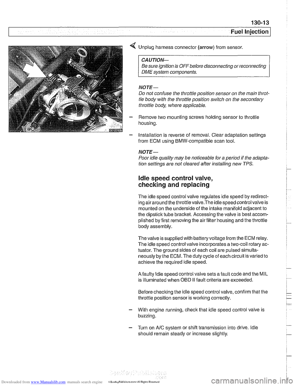
< Unplug harness connector (arrow) from sensor.
CAUTION-
Be sure ignition is OFF before disconnecting or reconnecting
DME system components.
NOTE-
Do not confuse the throttle position sensor on the main Nirot-
tle body with the throttle position switch on the secondary
throttle body, where applicable.
- Remove two mounting screws holding sensor to throttle
housing.
- Installation is reverse of removal. Clear adaptation settings
from ECM using BMW-compatible scan tool.
NOTE-
Poor idle quality may be noticeable for a period if the adapta-
tion settings are not cleared after installing new TPS.
ldle speed control valve,
checking and replacing
The idle speed control valve regulates idle speed by redirect-
inq airaround the throttlevalve.The idlespeed control valve is
mounted on the underside of the intake manifold adjacent to
the dipstick tube bracket. Accessing the valve is best accom-
plished by first removing the air filter housing and the throttle
body assembly.
The valve issupplied with
batteryvoltagefrom the ECM relay.
The idle speed control valve incorporates a two-coil rotary ac-
tuator. The ground sides of each coil are pulsed
sirnulta-
neously by the ECM. The duty cycle of each circuit is varied to
achieve the required idle speed.
Afaulty ldle speed control valve sets afault code and the MIL
is illuminated when
OED II fault criteria are exceeded.
Before checking the idle speed control valve, confirm that the
throttle position sensor is working correctly.
- With engine running, check that idle speed control valve is
buzzing.
- Turn on AIC system or shift transmission into drive. ldle
should remain steady or increase slightly.
Page 410 of 1002
Downloaded from www.Manualslib.com manuals search engine
I Fuel Injection
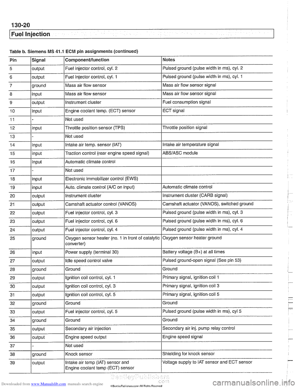
Table b. Siemens MS 41.1 ECM pin assignments (continued)
Pin
l~iqnal I Componentlfunction 1 Notes I - I I
5 loutput I Fuel injector control, cyl. 2 I Pulsed ground (pulse width in ms), cyl. 2 I I I
6 loutput /Fuel injector control, cyi. 1 I Pulsed ground (pulse width in ms), cyl. 1
I I I
14 linput I Intake air temp. sensor (IAT) I Intake air temperature signal
- 7
8
9
10
11
12
13
ground
input
output
input
input
15
16
17 18
19
20
21
22
I - I I
35 loutput /Secondary air injection ISecondary air inj. pump relay control
25
26
27
28
29
30
31
32
33
36
/output I Engine speed output IEngine speed signal
Mass air flow sensor
Mass air flow sensor
instrument cluster
Engine coolant
temp.
(ECT) sensor
Not used
Throttle position sensor (TPS)
Not used
input
input
input
input
output
output
out~ut
37 1 - /Not used I
Mass air flow sensor signal
Mass air flow sensor signal
Fuel consumption signal
ECT signal
Throttle position signal
ground
input
output
ground
output
output
output
ground
output
Traction control (rear engine speed signal) Automatic climate control
Not used Electronic immobilizer control (EWS)
Auto. climate control
(AIC on input)
instrument
cluster
Camshaft actuator control (VANOS)
Fuel iniector control, cvl.
3
AES/ASC module
Automatic climate control instrument cluster (CARE signal)
Camshaft actuator (VANOS), switched ground
Pulsed ground (pulse width in
ms), cyl. 3
Oxygen sensor heater (no. 1 in front of catalytic
converter)
Power supply (terminal
30)
Idle speed control valve
Ground
Ignition coil control, cyl.
1
Ignition coil control, cyl. 3
Ignition coil control, cyl. 5
Ground Fuel injector control, cyl.
5
Oxygen sensor heater ground
Battery voltage
(E+) at all times
Pulsed ground-open signal (See pin
53)
Ground
Primary signal, ignition coil
1
Primary signal, ignition coil 3
Primary signal, ignition coil 5
Ground
Pulsed ground (pulse width in ms), cyl
5
Page 422 of 1002
Downloaded from www.Manualslib.com manuals search engine
Fuel Injection
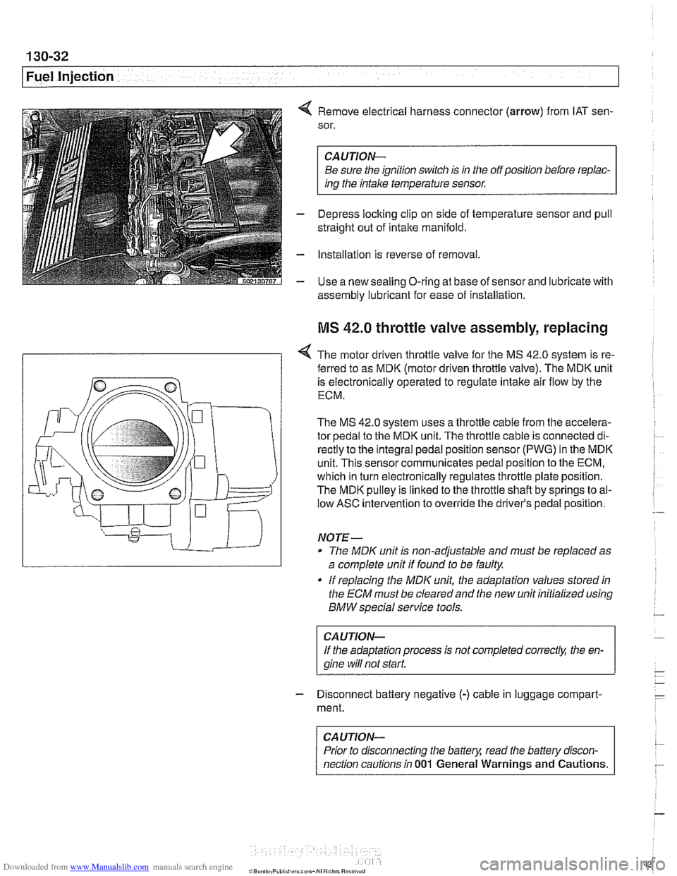
4 Remove electrical harness connector (arrow) from IAT sen-
sor.
CAUTION-
Be sure the ignition switch is in the off position before repiac-
ins the intake temperature sensor.
- Depress loclting clip on side of temperature sensor and pull
straight out of intake manifold.
- Installation is reverse of removal
- Use a new sealing O-ring at base of sensor and lubricate with
assembly lubricant for
ease of installation
MS 42.0 throttle valve assembly, replacing
< The motor driven throttle valve for the MS 42.0 system is re-
- ferred to as MDK (motor driven throttle valve). The MDK unit
is electronically operated to regulate intake air flow by the
ECM.
The
MS 42.0 system uses a throttle cable from the accelera-
tor pedal to the MDK unit. The throttle cable is connected di-
rectly to the integral pedal position sensor
(PWG) in the MDK
unit. This sensor communicates pedal position to the ECM,
which in turn electronically regulates throttle plate position.
The MDK pulley is linked to the throttle shaft by springs to al-
low ASC intervention to override the driver's pedal position.
NO TE -
The MDIC unit is non-adjustable and must be replaced as
a complete unit if found to be faulty.
if replacing the
MDK unit, the adaptation values stored in
the ECM must be clearedand the new unit initialized using
BMW special service tools.
CAUTION-
If the adaptation process is not completed correct& the en-
gine wiii
not start.
- Disconnect battery negative (-) cable in luggage compart-
ment.
CAUTION-
Prior to disconnecting the battern read the battely discon-
nection cautions in
001 General Warnings and Cautions.
Page 442 of 1002
Downloaded from www.Manualslib.com manuals search engine
.. .-
/Fuel lnjeciion
NOJE-
With engine oft disconnect harness connector and checlc
heating element resistance between white wires on the sen-
sor side of harness. If the element is electrically open (no
continuity), replace sensor.
- If oxygen sensor does not produce a fluctuating voltage and
preheater circuit is
OK, replace sensor.
NOJE-
If not already applied, coat oxygen sensor threads w~th anti-
seize compound before installat~on. Do not get the com-
pound on the sensor tip.
Tightening torque Oxygen sensor to exhaust system
55 Nm (41 ft-lb)
Fuel injectors, checking and replacing
The fuel iniectors are switched on and off (oaened and
closed)
by'the ECM. The injectors are connkcted to acom-
mon power source. A ground signal from the ECM is used to
open and close the injectors.
CA U JIOG
Use only a digital multimeter or an LED injector tester when
testing injectors or wiring. Use of an analog
VOM or incan-
descent test light may damaqe the engine controlmodule.
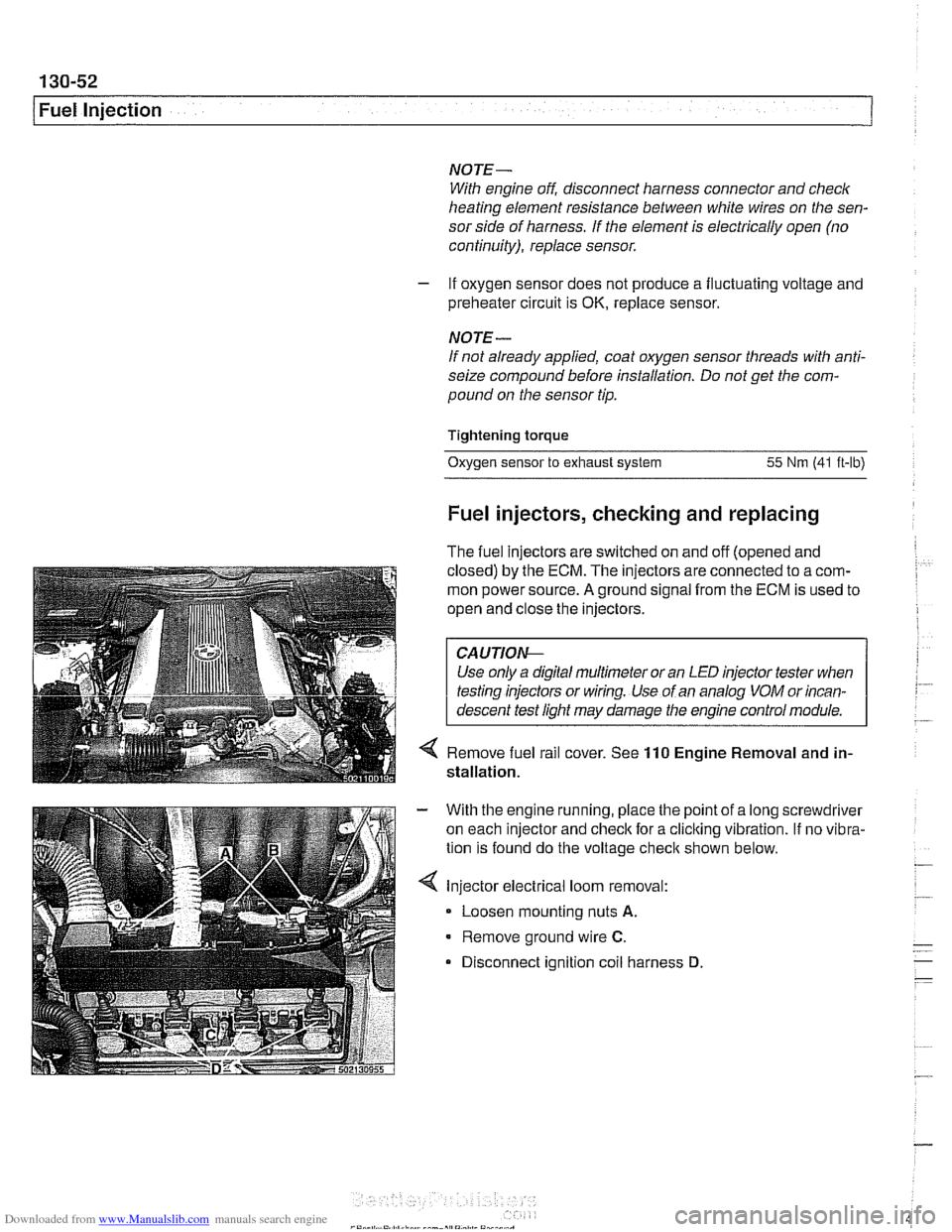
4 Remove fuel rail cover. See 110 Engine Removal and in-
stallation.
With the engine running, place the point of a long screwdriver
on each injector and check for a cliclting vibration.
If no vibra-
tion is found do the voltage
checit shown below.
Injector electrical loom removal:
- Loosen mounting nuts A.
Remove ground wire C.
Disconnect ignition coil harness D