Ignition switch BMW 528i 1998 E39 Owner's Guide
[x] Cancel search | Manufacturer: BMW, Model Year: 1998, Model line: 528i, Model: BMW 528i 1998 E39Pages: 1002
Page 508 of 1002
Downloaded from www.Manualslib.com manuals search engine
170-1 2
I Radiator and Cooling System
Tightening torques
Block drain plug to
block 25 Nm (1 8 ft-ib)
Radiator drain plug to radiator
2-3 Nm (18-27 in-lb)
Coolant, draining and filling (V-8 models)
WARNING -
Allow the cooling system to cool before opening or draining
the cooling system.
- Raise front of car and support safely.
I WARNING- 1
Make sure the car is stable and well supported at all times.
Use a professional automotive lift
orjack stands designed for
I the purpose. A floorjack is not adequate support 1
- Remove splash shield from under engine.
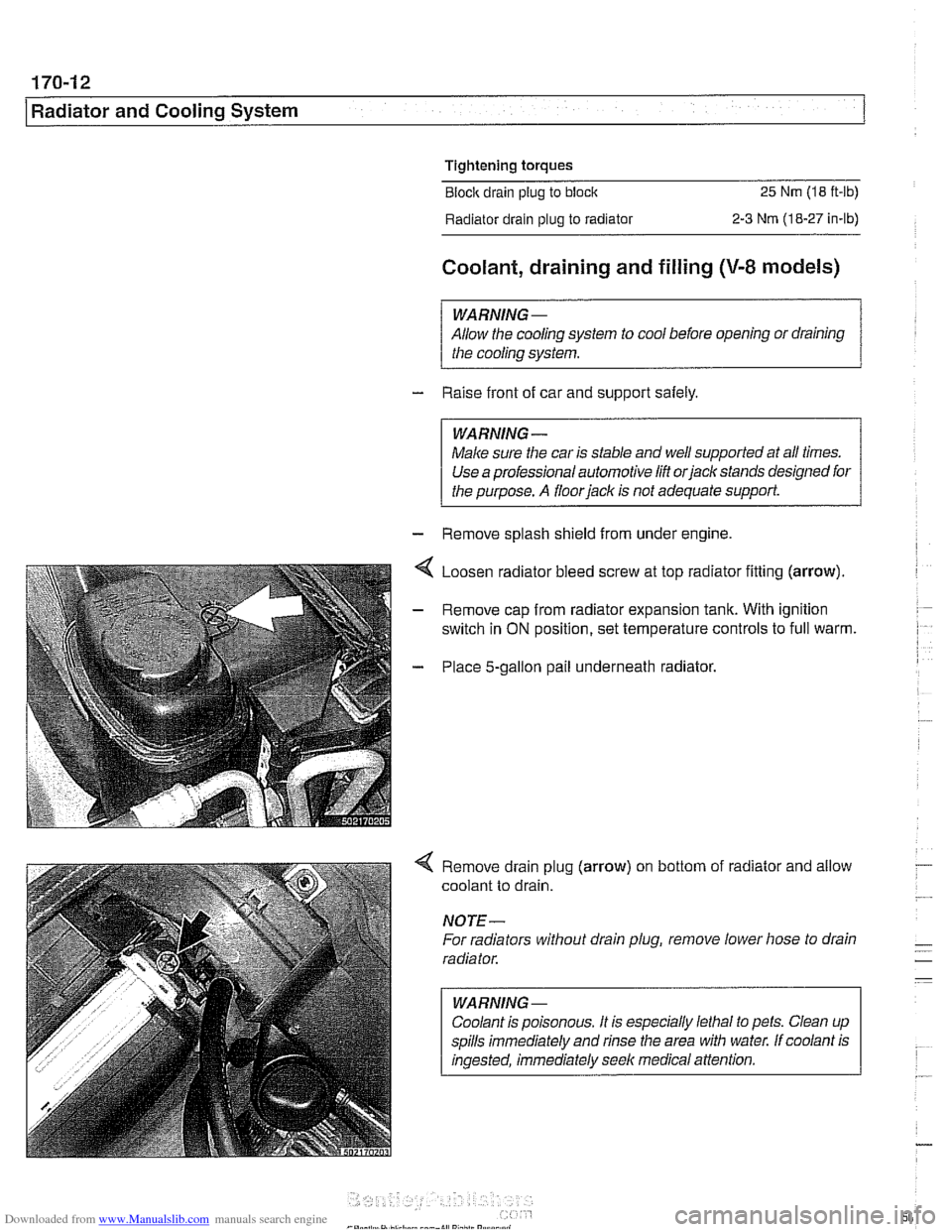
Loosen radiator bleed screw at top radiator fining (arrow).
Remove cap from radiator expansion tank. With ignition
switch in
ON position, set temperature controls to full warm.
Place 5-gallon pail underneath radiator.
4 Remove drain plug (arrow) on bottom of radiator and allow
coolant to drain.
NOTE-
For radiators without drain plug, remove lower hose to drain
radiator.
WARNING
-
Coolant is poisonous. It is especially lethal to pets. Clean up
spills immediately and rinse the area with water. If coolant is
ingested, immediately seek medical attention.
Page 509 of 1002
Downloaded from www.Manualslib.com manuals search engine
170-1 3
Radiator and Cooling ~vsteml
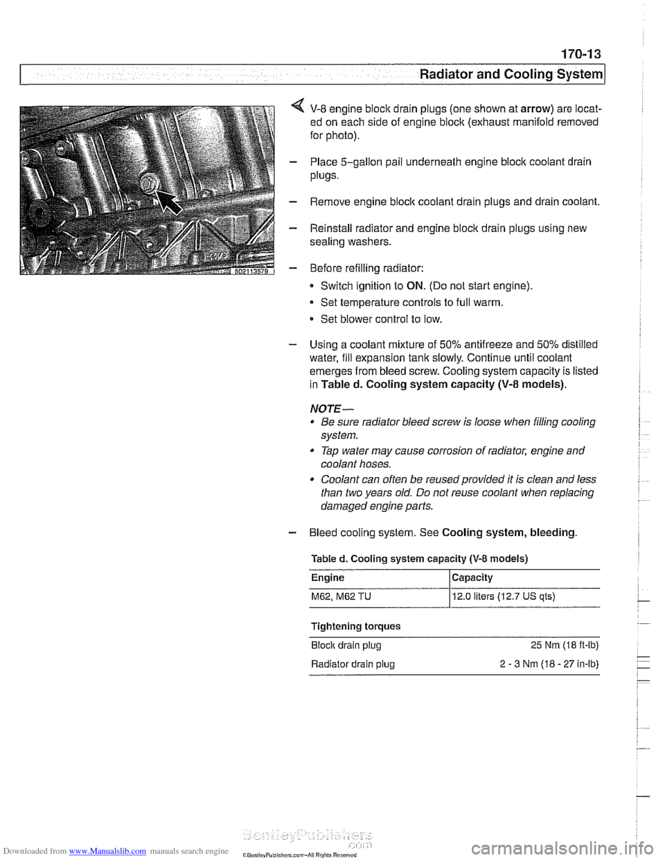
< V-8 engine bloclc drain plugs (one shown at arrow) are locat-
ed on each side of engine block (exhaust manifold removed
for photo).
- Place 5-gallon pail underneath engine block coolant drain
plugs.
- Remove engine bloclc coolant drain plugs and drain coolant.
- Reinstall radiator and engine block drain plugs using new
sealing washers.
- Before refilling radiator:
Switch ignition to
ON. (Do not start engine)
Set temperature controls to full warm.
- Set blower control to low.
- Using a coolant mixture of 50% antifreeze and 50% distilled
water, fill expansion tank slowly. Continue until coolant
emerges from bleed screw. Cooling system capacity is listed
in Tabled. Cooling system capacity
(V-8 models).
NOTE- Be sure radiator bleed screw is loose when filling cooling
system.
Tap water may cause corrosion of radiator, engine and
coolant hoses.
Coolant can often be reused provided it is clean and less
than two years old. Do not reuse coolant when replacing
damaged engine parts.
- Bleed cooling system. See Cooling system, bleeding
Tabled. Cooling system
capacity (V-8 models)
M62, M62 TU 12.0 liters (12.7 US qts)
Tightening torques
Block drain plug
25 Nm (18 ft-lb)
Radiator drain plug
2 - 3 Nm (18 - 27 in-lb)
Page 606 of 1002
Downloaded from www.Manualslib.com manuals search engine
250-8
Gearshift Linkage
-;Ag Gate "",?it.,
Shift interlock, checking function
(automatic transmission)
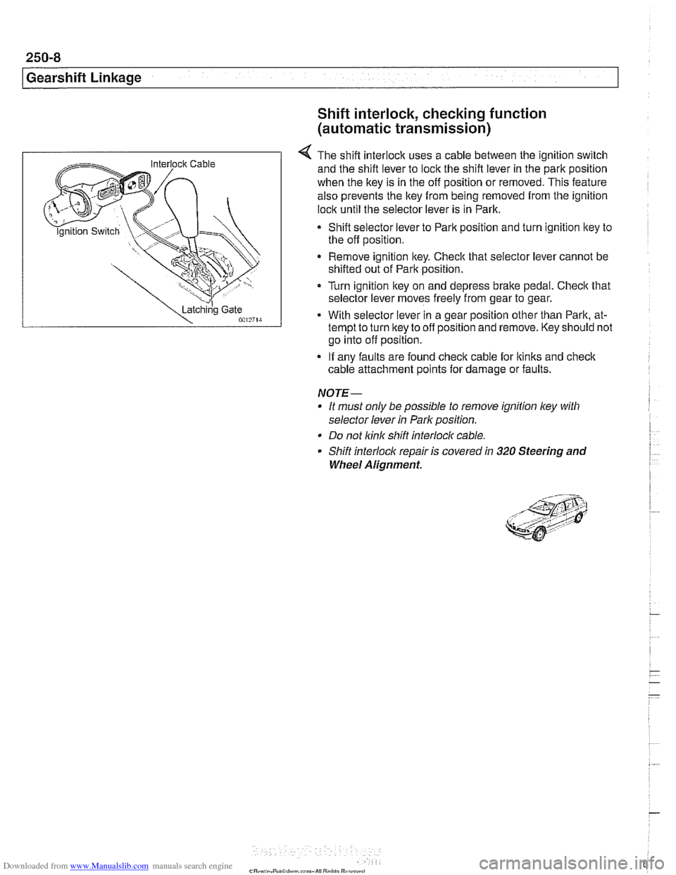
4 The shift interlock uses a cable between the ignition switch
and the shift lever to lock the shift lever in the park position
when the key is in the off position or removed. This feature
also prevents the key
from being removed from the ignition
lock until the selector lever is in Park.
Shift selector lever to Park position and turn ignition key to
the off position.
Remove ignition key. Checlc that selector lever cannot be
shifted out of Park position.
Turn ignition lkey on and depress
brake pedal. Checlc that
selector lever moves freely from gear to gear.
With selector lever in a gear position other than Park, at-
tempt to turn lkey to off position and remove. Key should not
go into off position.
If any faults are found check cable for lkinks and
check
cable attachment points for damage or faults.
NOTE-
* It must only be possible to remove ignition ley with
selector lever
in Park position.
* Do not link shift interlocl( cable.
Shift interlock repair is covered
in 320 Steering and
Wheel Alignment.
Page 633 of 1002
Downloaded from www.Manualslib.com manuals search engine
Suspension, Steering and Brakes - ~enerail
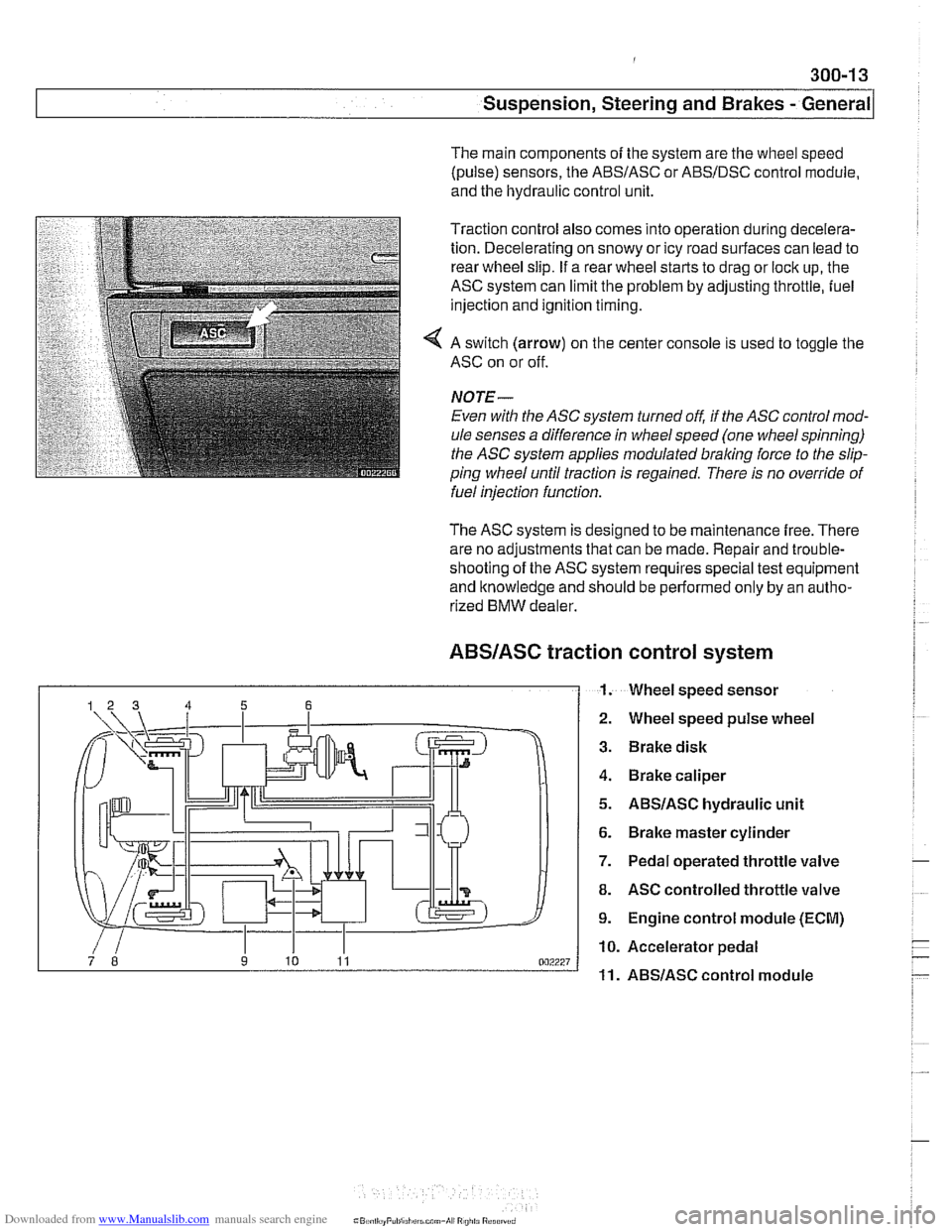
The main components of the system are the wheel speed
(pulse) sensors, the
ABSIASC or ABSIDSC control module,
and the hydraulic control unit.
Traction control also comes into operation during decelera-
tion. Decelerating on snowy or icy road surfaces can lead to
rear wheel slip. If a rear wheel starts to drag or lock up, the
ASC system can limit the problem by adjusting throttle, fuel
injection and ignition timing.
4 A switch (arrow) on the center console is used to toggle the
ASC on or off.
NOJE-
Even with the ASC system turned off, if the ASC control mod-
ule senses a difference in wheel speed (one wheel spinning)
the
ASC system applies modulated braling force to the slip-
ping wheel until traction is regained. There is no override of
fuelinjection function.
The ASC system is designed to be maintenance free. There
are no adjustments that can be made. Repair and trouble-
shooting of the ASC system requires special test equipment
and knowledge and should be performed only by an autho-
rized
BMW dealer.
ABSIASC traction
I 1.
control system
Wheel speed sensor
Wheel speed pulse wheel
Brake disk
Brake caliper
ABSIASC hydraulic unit
Brake master cylinder
Pedal operated throttle valve
ASC controlled throttle valve
Engine control module (ECM)
Accelerator pedal
ABSlASC control module
Page 634 of 1002
Downloaded from www.Manualslib.com manuals search engine
300-1 4
I Susoension. Steerina and Brakes - General
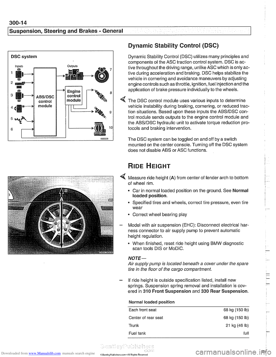
DSC system I
Dynamic Stability Control (DSC)
Dynamic Stability Control (DSC) utilizes many principles and
components of the ASC traction control system. DSC is ac-
tive throughoutthe driving range, unlike ASC which is only ac-
tive during acceleration and braking. DSC helps stabilize the
vehicle in cornering and avoidance maneuvers by adjusting
engine controls such as throttle, ignition, fuel injection and the
application of
brake pressure individually to the wheels.
Inputs
fi- 0
2 4-* .. o
[11-' IJ
411m4
3?-
G
4 The DSC control module uses various inputs to determine
vehicle instability during braking, cornering, or reduced trac-
tion situations. Based upon these inputs the ABSIDSC con-
trol module sends outputs to the engine control module and
the ABSIDSC hydraulic unit to activate torque reduction pro-
tocols and braking intervention.
-
ABSIDSC control module
OUI~YIS
4
The DSC system can be toggled on and off by a switch
mounted on the center console. Turning off the DSC system
does not disable ABS or ASC functions.
+
Measure ride height (A) from center of fender arch to bottom
of wheel rim.
Car in normal loaded position on the ground. See Normal
loaded position.
Engine
control
module
Specified tires and wheels, correct tire pressure, even tire
wear
-'* 9-
.%A
Correct wheel bearing play
T'== ..t, 9 B
-.m
Model with air suspension (EHC): Disconnect electrical har-
ness connector to air supply pump to prevent automatic
height regulation.
When finished, reset ride height using BMW diagnostic
scan tools DIS or
MoDiC.
NOTE-
Airsupply pump is located beneath a cover under the spare
tire in the floor of the cargo compartment.
- If ride height is outside specification listed, install new
springs. Suspension spring removal and installation is cov-
ered in
310 Front Suspension and 330 Rear Suspension.
Normal loaded position
Each front seat 68 kg (150 Ib)
Center of rear seat 68 kg (150 lb)
Trunk 21 kg (46 lb)
Fuel tank full
Page 660 of 1002
Downloaded from www.Manualslib.com manuals search engine
I Steering and Wheel Alignment
This repair group covers steering wheel and column removal
and steering system service, including wheel alignment infor-
mation.
NOTE-
Ignition loclc cylinder replacement is covered in this sec-
tion.
a For information on steering column mounted switches, in-
cluding the ignition switch, see
612 Switches.
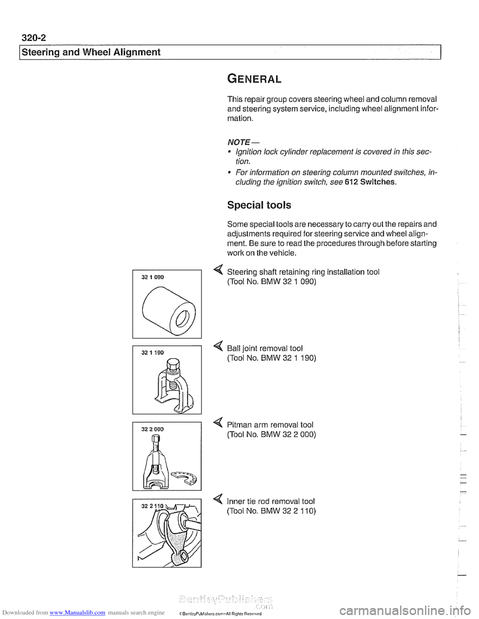
Special tools
Some special tools are necessary to carry out the repairs and
adjustments required for steering service and wheel align-
ment. Be sure to read the procedures through before starting
work on the vehicle.
4 Steering shafl retaining ring installation tool
(Tool No. BMW 32
1 090)
4 Bail joint removal tool
(Tool No. BMW 32
1 190)
4 Pitman arm removal tool
(Tool No. BMW 32 2
000)
4 Inner tie rod removal tool
(Tool No. BMW 32 2
110)
Page 669 of 1002
Downloaded from www.Manualslib.com manuals search engine
Steering and Wheel ~li~nrnentl
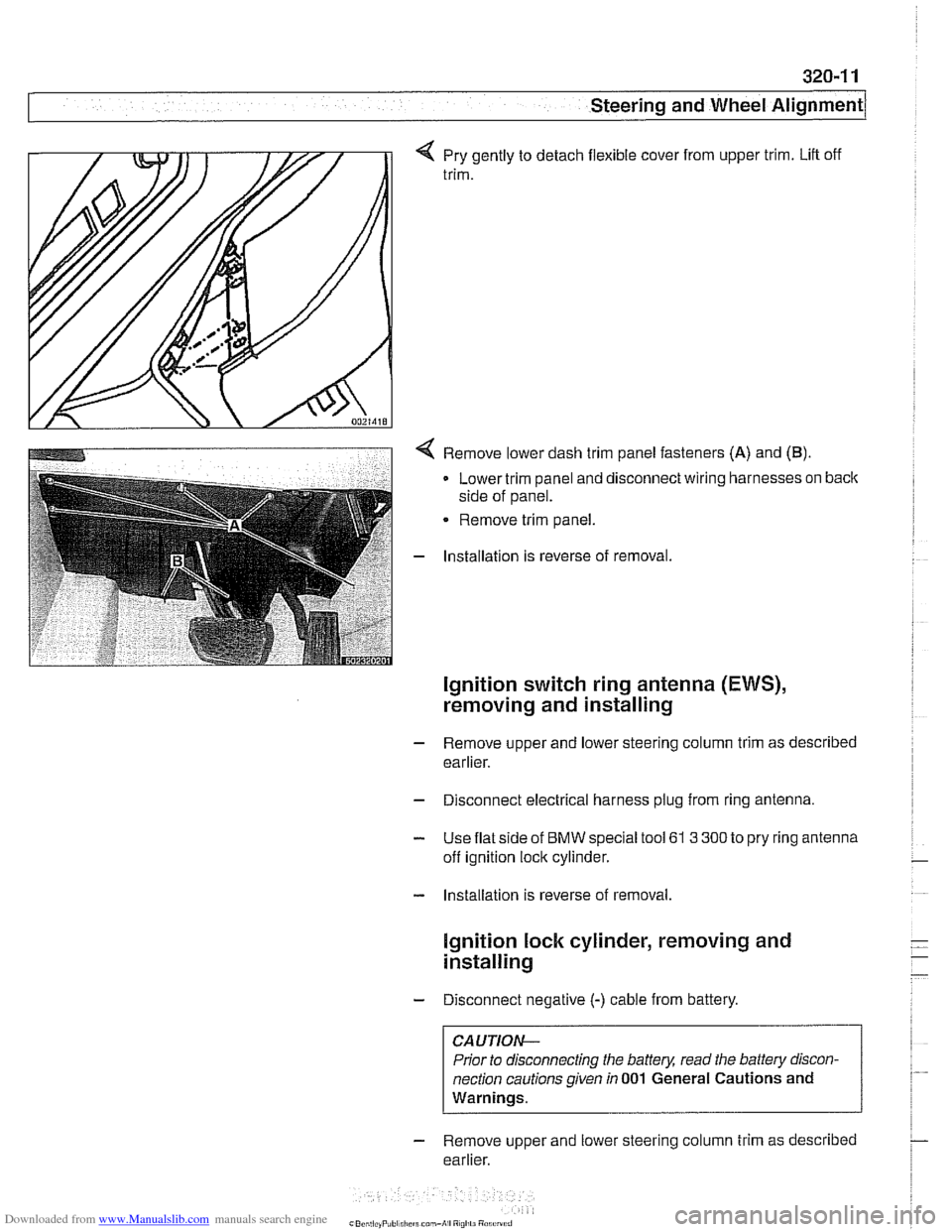
q Pry gently to detach flexible cover from upper trim. Lift off
trim.
< Remove lower dash trim panel fasteners (A) and (B).
Lower trim panel and disconnect wiring harnesses on back
side of panel.
Remove trim panel.
- Installation is reverse of removal.
Ignition switch ring antenna (EWS),
removing and installing
- Remove upper and lower steering column trim as described
earlier.
- Disconnect electrical harness plug from ring antenna.
- Use flat side of BMW special tool 61 3 300 to pry ring antenna
off ignition lock cylinder.
- Installation is reverse of removal.
lgnition lock cylinder, removing and
installing
- Disconnect negative (-) cable from battery.
CAUTION-
Prior to disconnecting the battery, read the battery discon-
nection cautions given
in 001 General Cautions and
Warnings.
- Remove upper and lower steering column trim as described
earlier.
Page 670 of 1002
Downloaded from www.Manualslib.com manuals search engine
I Steering and Wheel Alignment
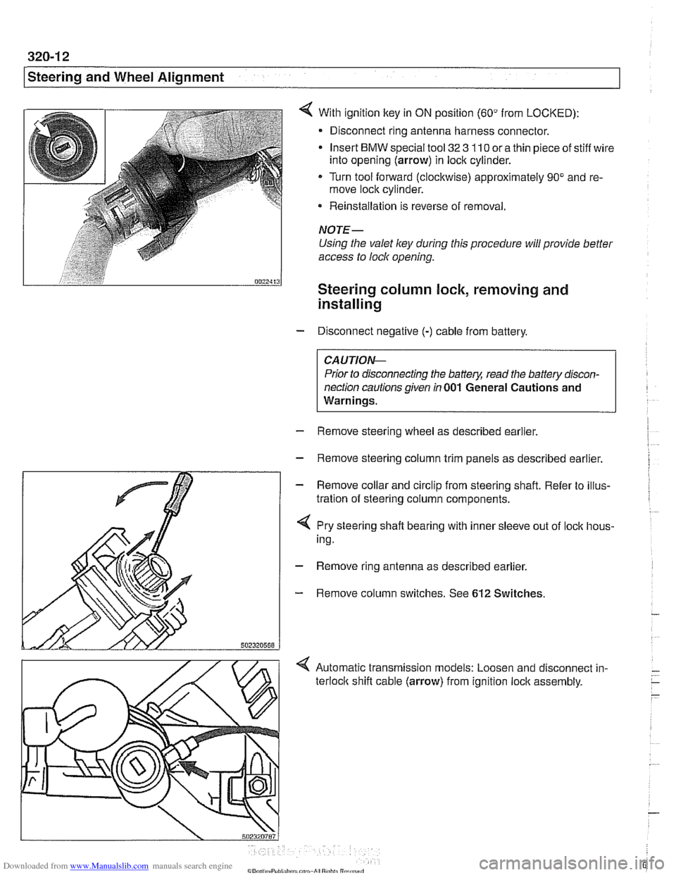
With ignition key in ON position (60" from LOCKED):
- Disconnect ring antenna harness connector.
Insert
BMW special tool 32 3 110 or a thin piece of stiff wire
into opening (arrow) in lock cylinder.
Turn tool forward (clockwise) approximately 90" and re-
move lock cylinder.
* Reinstallation is reverse of removal.
NOTE-
Using the valet ley during this procedure will provide better
access to lock opening.
Steering column lock, removing and
installing
- Disconnect negative (-) cable from battery.
CAUTIO&
Prior to disconnecting the battery, read the battery discon-
nection cautions given
in 001 General Cautions and
Warnings.
- Remove steering wheel as described earlier.
- Remove steering column trim panels as described earlier.
- Remove collar and circlip from steering shaft. Refer to illus-
tration of steering column components.
4 Pry steering shaft bearing with inner sleeve out of lock hous-
ing.
- Remove ring antenna as described earlier.
- Remove column switches. See 612 Switches.
< Automatic transmission models: Loosen and disconnect in-
terloclc shift cable (arrow) from ignition lock assembly.
Page 671 of 1002
Downloaded from www.Manualslib.com manuals search engine
Steering and Wheel Alignment
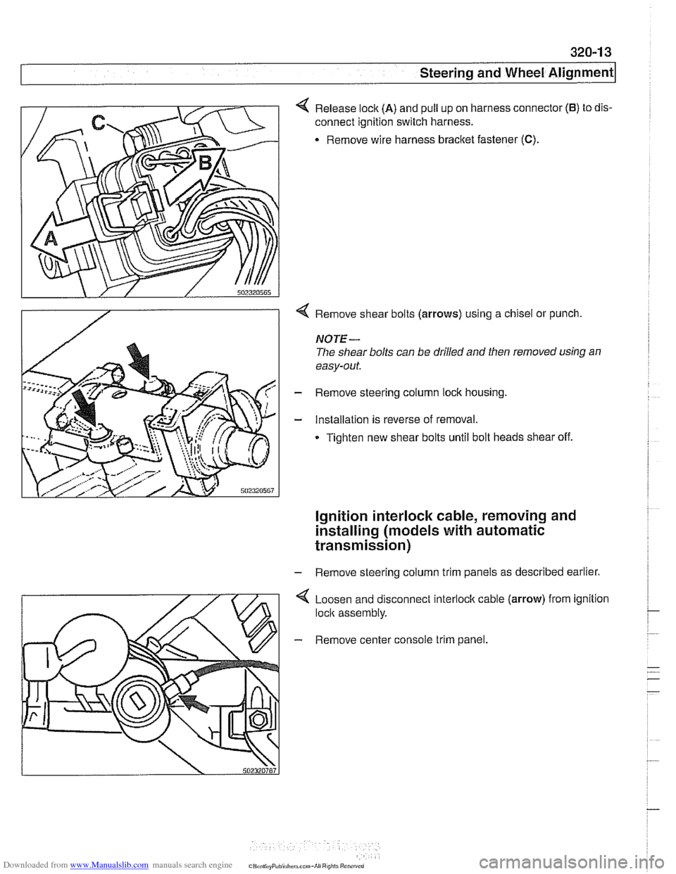
4 Release lock (A) and pull up on harness connector (6) to dis-
connect ignition switch harness.
. Remove wire harness bracket fastener (C).
4 Remove shear bolts (arrows) using a chisel or punch.
NOTE-
The shear bolts can be drilled and then removed using an
easy-out.
- Remove steering column lock housing.
- Installation is reverse of removal.
Tighten new shear bolts until bolt heads shear off.
ignition interlock cable, removing and
installing (models
with automatic
transmission)
- Remove steering column trim panels as described earlier.
4 Loosen and disconnect interlock cable (arrow) from ignition
lock assembly.
- Remove center console trim panel.
Page 785 of 1002
Downloaded from www.Manualslib.com manuals search engine
340-23
Brakes
- Using flat-bladed screwdriver, reach into brake drum through
lug bolt hole. Turn brake adjuster until wheel no longer turns.
Back adjuster off
12 notches.
Parking brake adjusting (initial)
Back
off adjuster through wheel
lug bolt hole 12 notches
- Working inside car, set parking brake several times to seat
cable. Then pull parking brake
lever up two notches. Tighten
cable adjusting nuts until it is just possible to turn rear wheels
with slight resistance.
- Release lever and make sure rear wheels turn freely
- Turn on ignition. Pull up parlting brake lever 1 notch and
make sure that parking bralte warning light comes on. if not,
adjust parking bralte warning light contact switch.
- Install parking brake lever boot. Install road wheel lug bolts.
Tightening torque Road
wheel to hub 120 i. 10 Nrn (89 i- 7 ft-lb)
Parking brake shoes, removing and
installing
- Raise rear of car and remove road wheels.
WARNING-
Make sure that the car is firmly supported on jack stands de-
signed for
the purpose. Place jack stands beneath structural
chassis points. Do not place
jaclc stands under suspension
parts.
- Without disconnecting brake fluid hose, remove rear bralte
calipers from trailing arms. Remove rear brake rotors as de-
scribed earlier.
CAUTION-
Do not let the brake caliper assembly hang from the brake
hose. Support caliper from chassis with strong wire.
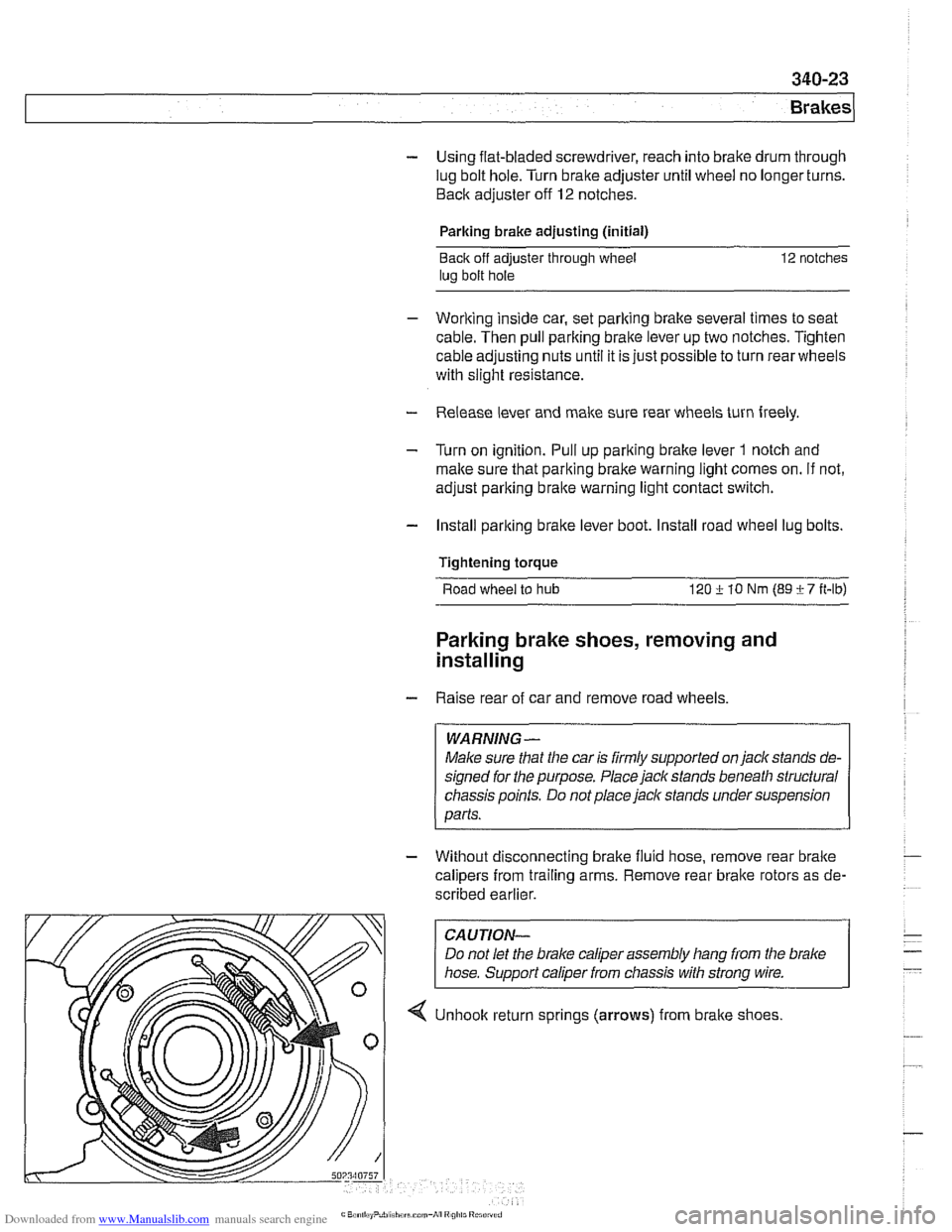
4 Unhook return sprlngs (arrows) from brake shoes