traction control BMW 528i 1998 E39 User Guide
[x] Cancel search | Manufacturer: BMW, Model Year: 1998, Model line: 528i, Model: BMW 528i 1998 E39Pages: 1002
Page 692 of 1002
Downloaded from www.Manualslib.com manuals search engine
320-34
I Steerins and Wheel Alignment
Front toe and toe difference angle
Toe is the difference in the distance between the front of the
front wheels and the rear of the front wheels. It is adjusted by
altering the length of the tie rods.
Toe difference angle determines the progressively different
paths taken by the front wheels as the car is turning. In
V-8
models, it is set by the pitman arm adjustment, but depends
on accurate setting of the toe.
Toe adjustments should only be made on specialized align-
ment equipment and only with the car in normal loaded posi-
tion, described below.
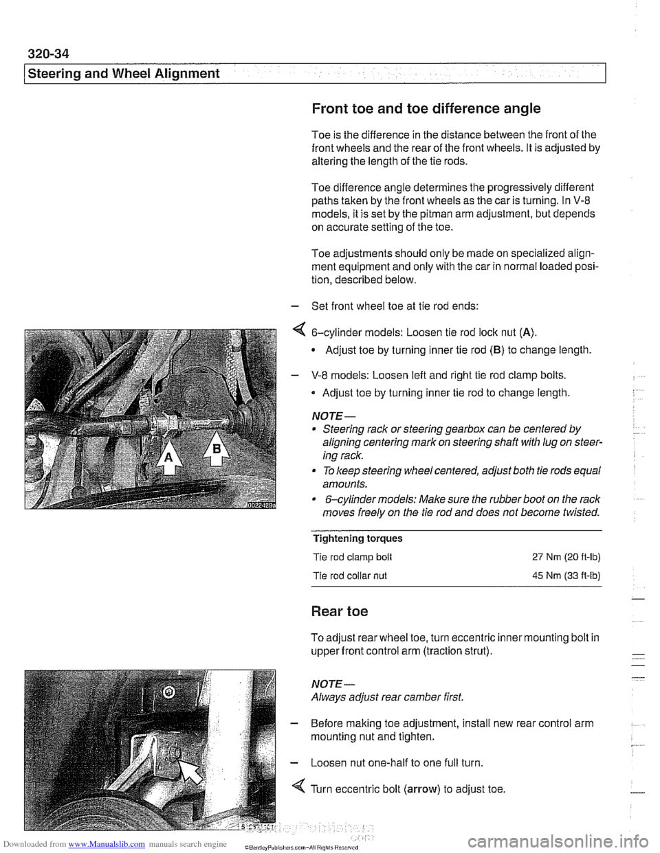
- Set front wheel toe at tie rod ends:
4 6-cylinder models: Loosen tie rod lock nut (A).
Adjust toe by turning inner tie rod (B) to change length
- V-8 models: Loosen left and right tie rod clamp bolts.
Adjust toe by turning inner tie rod to change length.
NOTE-
* Steering rack or steering gearbox can be centered by
aligning centering mark on steering shaft
with lug on steer-
ing rack.
To keep steering wheel centered, adjust both tie rods equal
amounts.
&cylinder models: Make sure the rubber boot on the rack
moves freely on the tie rod and does not become twisted.
Tightening torques
Tie rod clamp bolt
Tie rod collar
nut
27 Nm (20 ft-lb)
45 Nm (33 A-lb)
Rear toe
To adjust rear wheel toe, turn eccentric inner mounting bolt in
upper front control arm (traction strut).
NOTE-
Always adjust rear camber first.
- Before making toe adjustment, install new
mounting nut and tighten.
- Loosen nut one-half to one full turn.
4 Turn eccentric bolt (arrow) to adjust toe. rear
control arm
Page 697 of 1002
Downloaded from www.Manualslib.com manuals search engine
330 Rear Suspension
General . . . . . . . . . . . . . . . . . . . . . . . . . . . ,330-2
Special tools . . . . . . . . . . . . . . . . . . . . . . . . ,330-2
Rear suspension variations . . . . . . . . . . . . ,330-4
Rear Struts and Springs
(sedan models)
. . . . . . . . . . . . . . . . . . . . ,330-5
Rear strut assembly, removing
and installing
. . . . . . . . . . . . . . . . . . . . . . . ,330-5
Rear strut assembly, disassembling
and assembling
. . . . . . . . . . . . . . . . . . . . . ,330-7
Rear Shock Absorbers and
Springs (Sport Wagon models)
. . . . . ,330-9
Rear shock absorber, removing
and installing
. . . . . . . . . . . . . . . . . . . . . . . ,330-9
Coil spring, removing and installing . . . . . ,330-1 1
Air spring, removing and installing
. . . . . . ,330-12
Rear Suspension Arms,
Subframe and Bushings . . . . . . . . . . ,330-13
Rear suspension arm components . . . . . . ,330-1 3
Swing arm, removing and installing (sedan models)
. . . . . . . . . . . . . . . . . . . . . ,330-1 4
Swing arm, removing and installing (Sport Wagon models)
. . . . . . . . . . . . . . . ,330-16
Swing arm ball joint, replacing . . . . . . . . . ,330-1 9
Upper rear control arm, removing
and installing (sedan models)
. . . . . . . . . . .330-22
Upper rear control arm, removing
and installing (Sport Wagon models)
. . . . .330-23
Upper front control arm (traction strut),
removing and installing
. . . . . . . . . . . . . . . ,330-25
Rear axle assembly, removing and
installing (sedan models)
. . . . . . . . . . . . . ,330-26
Rear axle assembly, removing and
installing (Sport Wagon models)
. . . . . . . ,330-28
Rear subframe mounting bushings,
removing and installing
. . . . . . . . . . . . . . . .330-31
Rear Wheel Bearings . . . . . . . . . . .
Rear wheel bearing carrier, removing
and installing (sedan models)
. . . . . . .
Rear wheel bearing carrier, removing
and installing (Sport Wagon models)
. .
Rear wheel bearing, replacing . . . . . . .
Rear Stabilizer Bar
Stabilizer bar, removing and installing .
Stabilizer bar link, removing
and installing
. . . . . . . . . . . . . . . . . . . .
Electronic Height Control (EHC)
Component Replacement
. . . . . . .
Electronic height control (EHC)
components
.....................
Air compressor pump relay, removing
and installing
. . . . . . . . . . . . . . . . . . . .
EHC control module, removing
and installing
. . . . . . . . . . . . . . . . . . . .
Air supply unit, removing and installing
Ride height sensor, removing
and installing
. . . . . . . . . . . . . . . . . . . .
Page 700 of 1002
Downloaded from www.Manualslib.com manuals search engine
330-4
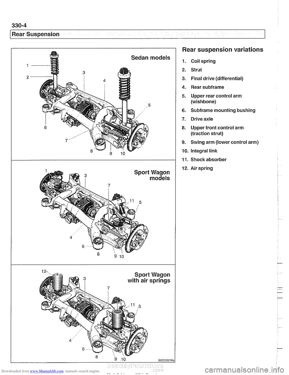
Rear Suspension Rear suspension variations
1. Coil spring
2. Strut
3. Final drive (differential)
4. Rear subframe
5. Upper rear control arm
(wishbone)
6. Subframe mounting bushing
7. Drive axle
8. Upper front control arm
(traction strut)
9. Swing arm (lower control arm)
10. Integral link
12. Air spring
I
Waaon
11. Shockabsorber
a m3 withair s~riias
Page 709 of 1002
Downloaded from www.Manualslib.com manuals search engine
330-1 3
Rear Suspension
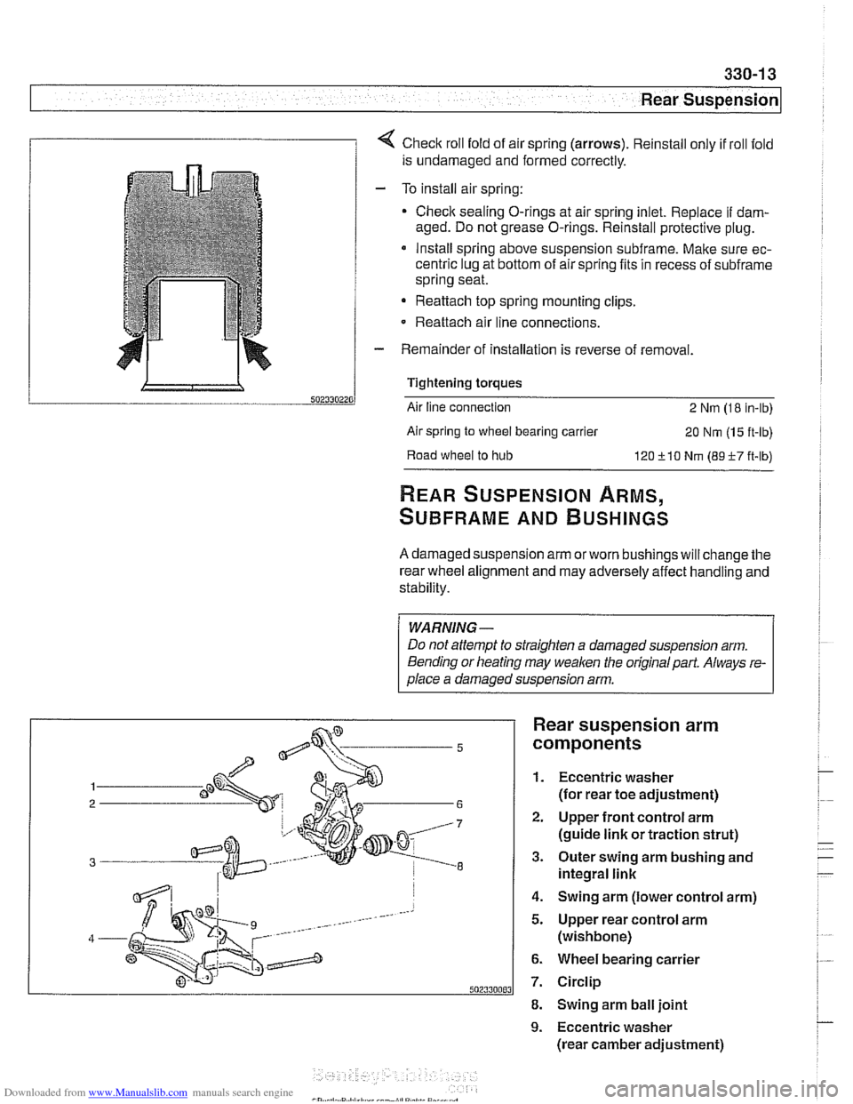
1 1 4 Check roll fold of air spring (arrows). Reinstall only if roll fold
is undamaged and formed correctly.
- To install air spring:
Check sealing O-rings at air spring inlet. Replace
if dam-
aged. Do not grease O-rings. Reinstall protective plug.
* Install spring above suspension subframe. Make sure ec-
centric lug at bottom of air spring fits in recess of
subframe
spring seat.
Reattach top spring mounting clips.
- Reattach air line connections.
- Remainder of installation is reverse of removal.
Tightening torques
Air line connection
2 Nm (1 8 in-lb)
Air spring
to wheel bearing carrier 20 Nm (1 5 ft-lb)
Road
wheel to hub 120 510 Nm (89-F-7 ft-lb)
REAR SUSPENSION ARMS,
SUBFRAME AND BUSHINGS
A damaged suspension arm orworn bushings will change the
rear wheel alignment and may adversely affect handling and
stability.
WARNING-
Do not attempt to straighten a damaged suspension arm.
Bending or heating may
weaken the original part. Always re-
olace a damaoed susoension arm.
Rear suspension arm
components
1. Eccentric washer
(for rear toe adjustment)
2. Upper front control arm
(guide link or traction strut)
3. Outer swing arm bushing and
integral link
4. Swing arm (lower control arm)
5. Upper rear control arm
(wishbone)
6. Wheel bearing carrier
7. Circlip
8. Swing arm ball joint
9. Eccentric washer
(rear camber adjustment)
Page 721 of 1002
Downloaded from www.Manualslib.com manuals search engine
330-25
Rear Suspension
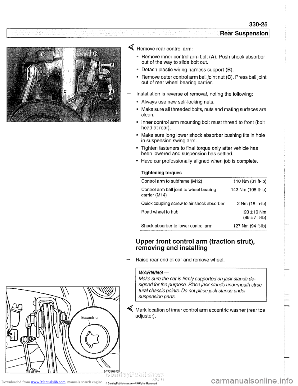
Remove rear control arm:
Remove inner control arm bolt
(A). Push shock absorber
out of the way to slide bolt out.
Detach plastic wiring harness support
(B).
Remove outer control arm ball joint nut (C). Press ball joint
out of rear wheel bearing carrier.
Installation is reverse of removal, noting the following:
* Always use new self-locking nuts.
Maite sure
ail threaded bolts, nuts and mating surfaces are
clean.
Inner control arm mounting bolt must thread to front
(bolt . head at rear).
Make sure long lower shock absorber bushing fits in hole
in suspension swing arm.
* Tighten fasteners to final torque only after vehicle has
been lowered and suspension has settled.
Have car professionally aligned when job is complete.
Tightening torques Control arm to
subframe (M12) 110 Nm (81 ft-ib)
Control arm ball joint to wheel bearing
142 Nm (105 ft-lb)
carrier
(M14)
Quick coupling screw to air shocit absorber
2 Nm (18 in-lb)
Road wheel to hub
Shoclc absorber to lower control arm 127 Nm (94 it-lb)
Upper front control arm (traction strut),
removing and installing
- Raise rear end of car and remove wheel.
WARNING-
Maice sure the car is firmly supported on jack stands de-
signed for the purpose. Place
jack stands underneath struc-
tural chassis points. Do not place jack stands under
< Mark location of inner control arm eccentric washer (rear toe
Page 722 of 1002
Downloaded from www.Manualslib.com manuals search engine
330-26
/ Rear Suspension
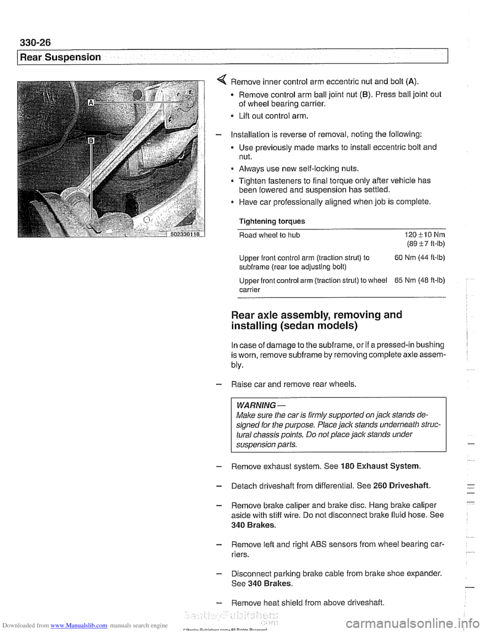
Remove inner control arm eccentric nut and bolt (A)
Remove control arm ball joint nut (6). Press ball joint out
of wheel bearing carrier.
Lifl out control arm.
Installation is reverse of removal, noting the following:
Use previously made
marks to install eccentric bolt and
nut.
Always use new self-locking nuts.
Tighten fasteners to final torque only after vehicle has
been lowered and suspension has settled.
0 Have car professionally aligned when job is complete.
Tightening
torques
Road wheel to hub 120klONm
(89 i7 ft-lb)
Upper front control arm (traction strut) to 60
Nm (44
ft-lb)
subframe (rear toe adjusting bolt)
Upper front control arm (traction strut) to wheel
65 Nm (48 ft-lb)
carrier
Rear axle assembly, removing and
installing (sedan models)
In case of damage to the subframe, or if a pressed-in bushing
is worn, remove
subframe by removing complete axle assem-
bly.
- Raise car and remove rear wheels.
WARNING-
Make sure the car is firmly supported on jack stands de-
signed for the purpose. Place jack stands underneath struc-
tural chassis points. Do not place
jack stands under
suspension parts.
- Remove exhaust system. See 180 Exhaust System
- Detach driveshaft from differential. See 260 Driveshaft.
- Remove brake caliper and brake disc. Hang brake caliper
aside with stiff wire. Do not disconnect brake fluid hose. See
340 Brakes.
- Remove lefl and right ABS sensors from wheel bearing car-
riers.
- Disconnect parking brake cable from brake shoe expander.
See 340 Brakes.
- Remove heat shield from above driveshaft.
Page 730 of 1002
Downloaded from www.Manualslib.com manuals search engine
(Rear Suspension
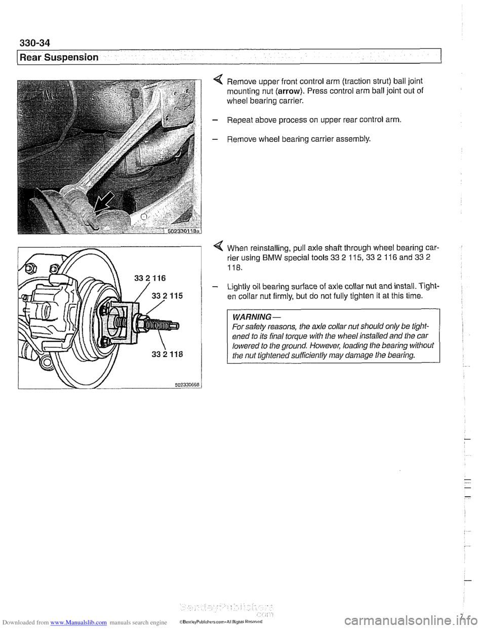
< Remove upper front control arm (traction strut) ball joint
mounting nut
(arrow). Press control arm ball joint out of
wheel bearing carrier.
- Repeat above process on upper rear control arm.
- Remove wheel bearing carrier assembly.
4 When reinstalling, pull axle shaft through wheel bearing car-
rier using
BMW special tools 33 2 115, 33 2 116 and 33 2
118.
- Lightly oil bearing surface of axle collar nut and install. T~ght-
en collar nut firmly, but do not fully tighten it at this time.
WARNING-
For safety reasons, the ale collar nut should only be tight-
ened to its final torque with the wheel installed and the car
lowered to
the ground. However, loading the bearing without
the nut tightened sufficiently may damage tlie bearing.
Page 731 of 1002
Downloaded from www.Manualslib.com manuals search engine
330-35
Rear Suspension
- Remainder of installation is reverse of removal, noting the fol-
lowing.
Always use new self-loclting nuts.
Make sure all threaded bolts, nuts and mating suriaces are
clean.
Make sure long lower strut bushing fits in hole in wheel
bearing carrier.
Tighten fasteners to final torque only after vehicle has
been lowered and suspension has settled.
Stake axle collar nut after tightening.
Tightening torques
ABS pulse sensor to wheel bearing carrier
8 Nm (6 ft-lb)
Brake rotor to hub 16 Nm (12 ft-lb)
Rear brake pad carrier (caliper) to wheel 65
Nm (48
ft-lb)
bearing carrier
Rear axle shaft to hub
(M27) 300 Nm (221 ft-lb)
Rear strut to wheel bearing carrier 127
Nrn (94 ft-lb)
Road wheel to hub
120+10 Nm
(89
i7 ft-lb)
Swing arm to wheel bearing carrier 256
Nrn (189 ft-lb)
Upper front control arm (traction strut) to 65 Nrn
(48
ft-lb)
wheel carrier
Upper rear control arm to wheel carrier 142
Nrn (105
ft-lb)
Rear wheel bearing carrier, removing and
installing (Sport Wagon models)
- Raise rear end of car and remove wheel.
WARNING-
Make sure the car is firmly supported on jack stands de-
signed for the purpose. Place jack stands underneath struc-
tural chassis points. Do not place jack stands under
suspension parts.
Models
with air springs: Disable air supply pump by discon-
necting electricalplug
beforepedormingany repairs. Pump is
located beneath a cover under the spare tire in the floor of the
cargo compartment.
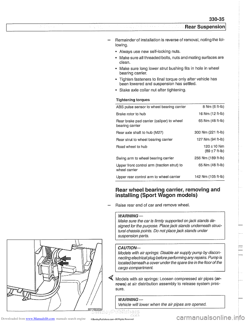
-- 4 Models with air springs: Loosen compressed air pipes (ar-
rows) at air distribution assembly to release system pres-
Page 734 of 1002
Downloaded from www.Manualslib.com manuals search engine
I Rear Suspension
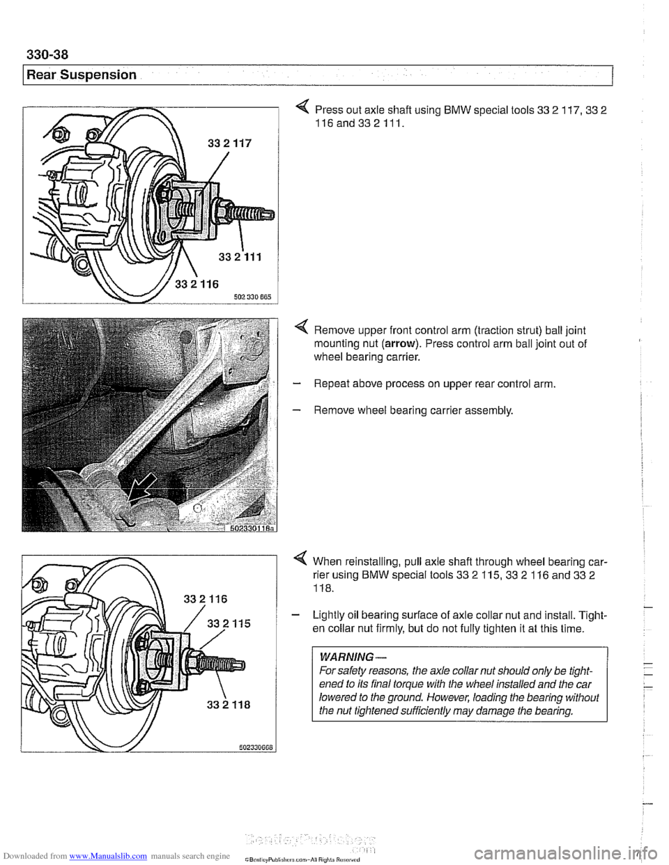
4 Press out axle shaft using BMW special tools 33 2 117. 33 2
116and332111.
4 Remove upper front control arm (traction strut) ball joint
mounting nut (arrow). Press control arm ball joint out of
wheel bearing carrier.
- Repeat above process on upper rear control arm.
- Remove wheel bearing carrier assembly.
4 When reinstalling, pull axle shafl through wheel bearing car-
rier using BMW special tools 33
2 115, 33 2 116 and 33 2
118.
- Lightly oil bearing surface of axle collar nut and install. Tight-
en collar nut firmly, but do not fully tighten it at this time.
WARNING-
For safety reasons, the axle collar nut should only be tight-
ened to its final torque with the wheel installed and the car
lowered to the ground. However, loading the bearing without
the nut tiqhtened
suificiently may darnaqe the bearina.
Page 735 of 1002
Downloaded from www.Manualslib.com manuals search engine
330-39
I Rear suspension1
- Remainder of installation is reverse of removal, noting the fol-
lowing.
Models with coil springs: Fit spring correctly in lower spring
seat.
* Models with air suspension: Fit eccentric lug at bottom of
air spring in recess of wheel carrier spring seat.
Always use new self-locking nuts.
- Make sure all threaded bolts, nuts and mating surfaces are
clean.
a Tighten fasteners to final torque only after vehicle has
been lowered and suspension has settled.
Stake axle collar nut afler tightening.
Tightening torques
ABS pulse sensor to wheel bearing 8 Nm (6
ft-lb)
carrier
Air spring to wheel bearing carrier 20 Nm (15 ft-lb)
Brake rotor to hub 16 Nm (12
it-lb)
Rear axle shaft to hub (M27) 300 Nm (221 ft-lb)
Rear brake pad carrier (caliper) to wheel 65 Nm (48 ft-lb)
bearing carrier
Road wheel to hub
120ilONm
(89 k7 ft-lb)
Swing arm to wheel bearing carrier 256 Nm (189 it-lb)
Upperfrontcontrol arm (traction strut) to 65 Nm (48 ft-lb)
wheel carrier
Upper rear control arm to wheel carrier 142 Nm (105 ft-lb)
Rear wheel bearing, replacing
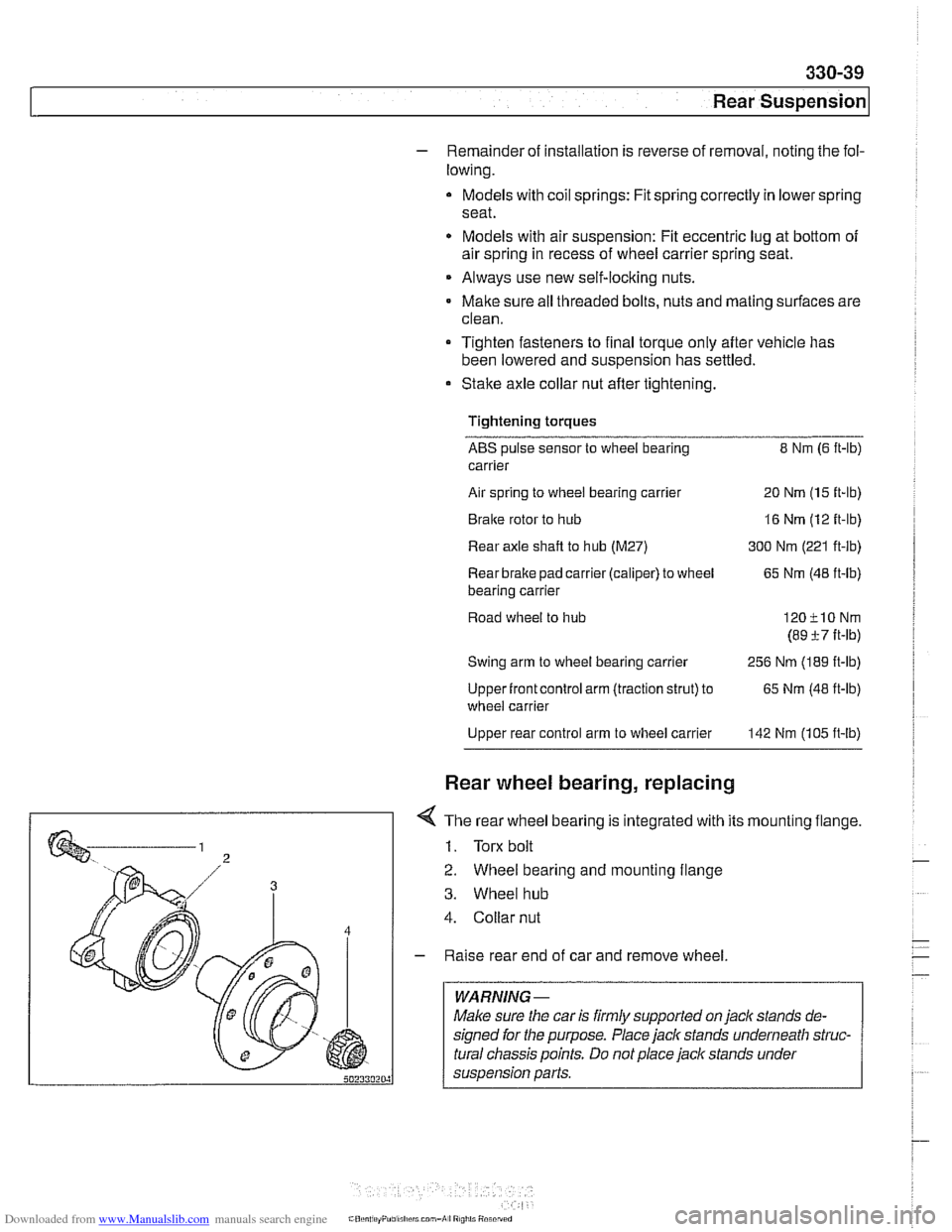
< The rear wheel bearing is integrated with its mounting flange.
1. Torx bolt
2. Wheel bearing and mounting flange
3. Wheel hub
4. Collar nut
- Raise rear end of car and remove wheel.
WARNING -
Make sure the car is firmly supported on jaclc stands de-
signed for the purpose. Place jack stands underneath struc-
tural chassis points. Do not place jack stands under
suspension parts.