ECT BMW 528i 1998 E39 Workshop Manual
[x] Cancel search | Manufacturer: BMW, Model Year: 1998, Model line: 528i, Model: BMW 528i 1998 E39Pages: 1002
Page 337 of 1002
Downloaded from www.Manualslib.com manuals search engine
1 19-1 7
Lubrication System
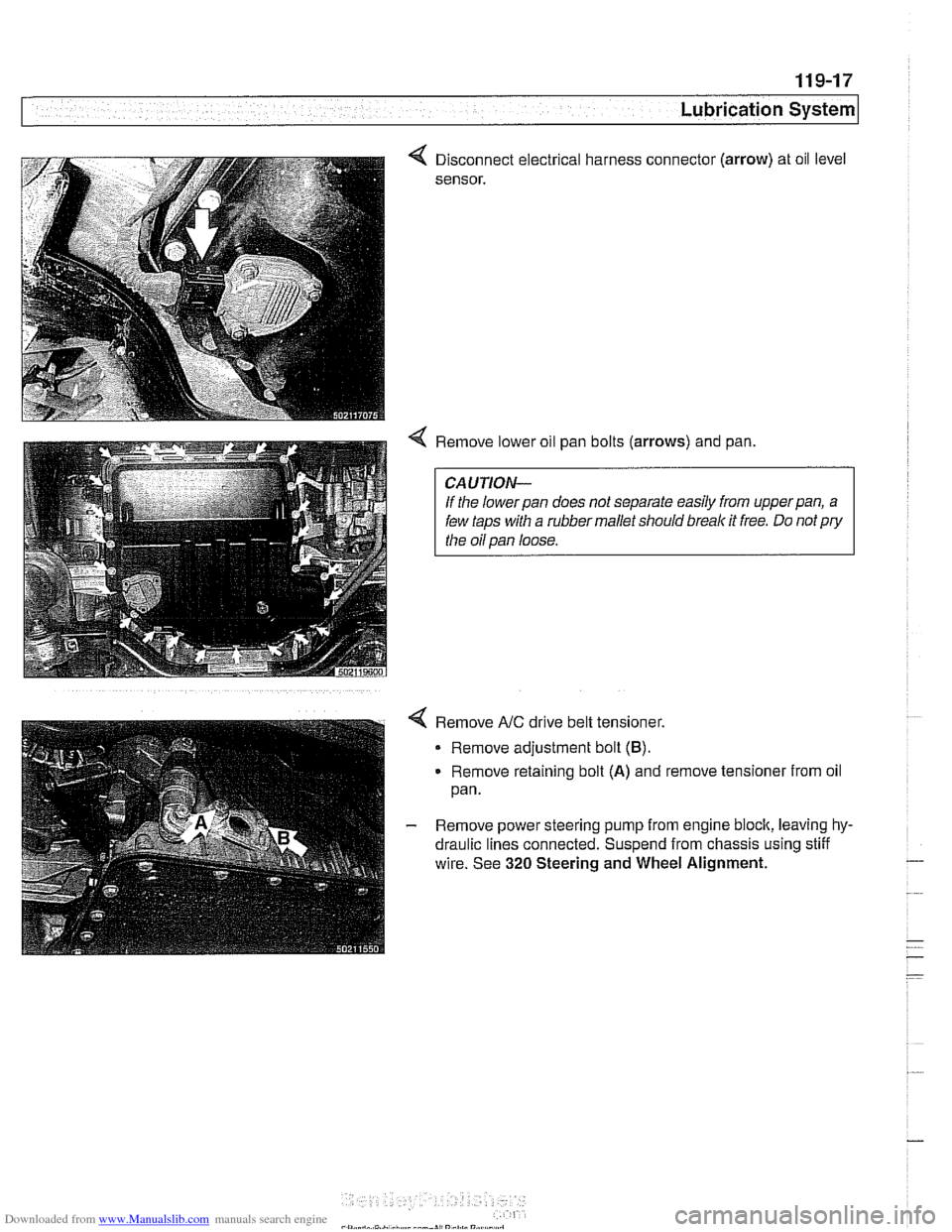
Disconnect electrical harness connect01
sensor.
. (arrow)
4 Remove lower oil pan bolts (arrows) and pan, oil
level
CAUTION-
If the lowerpan does not separate easily from upperpan, a
few taps with a rubber mallet should break it free. Do not pry
the oil pan loose.
Remove
NC drive belt tensioner.
Remove adjustment bolt
(B).
Remove retaining bolt (A) and remove tensioner from oil
pan.
- Remove power steering pump from engine block, leaving hy-
draulic lines connected. Suspend from chassis using stiff
wire. See
320 Steering and Wheel Alignment.
Page 338 of 1002
Downloaded from www.Manualslib.com manuals search engine
119-18
I Lubrication System
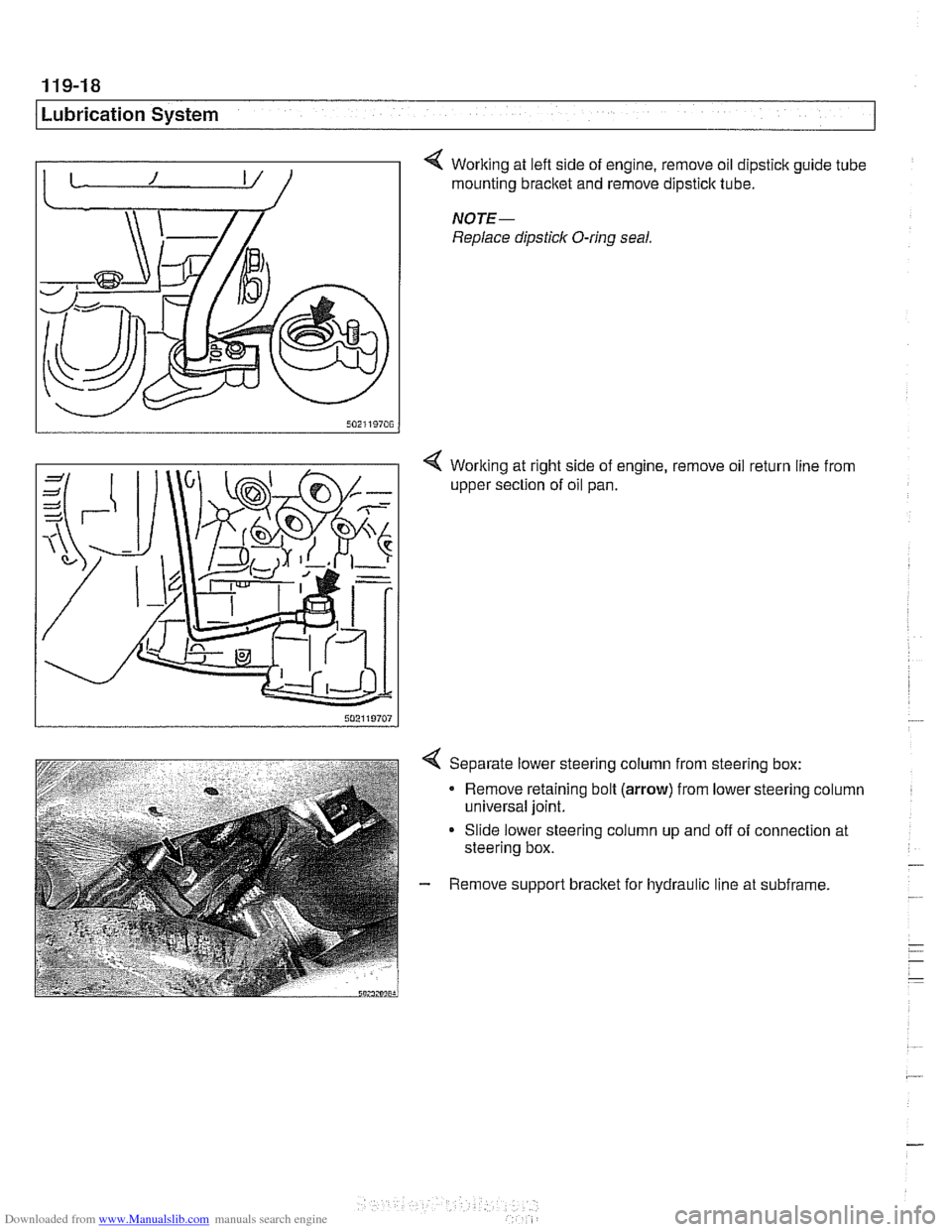
4 Working at lefl side of engine, remove oil dipstick guide tube 1 mounting bracket and remove dipstick tube.
NOTE-
Replace dipstick O-ring seal.
< Working at right side of engine, remove oil return line from
upper section of oil pan.
4 Separate lower steering column from steering box:
Remove retaining bolt
(arrow) from lower steering column
universal joint.
Slide lower steering column up and off of connection at
steering box.
- Remove support bracket for hydraulic line at subframe.
Page 340 of 1002
Downloaded from www.Manualslib.com manuals search engine
Lubr~cat~on System r- -
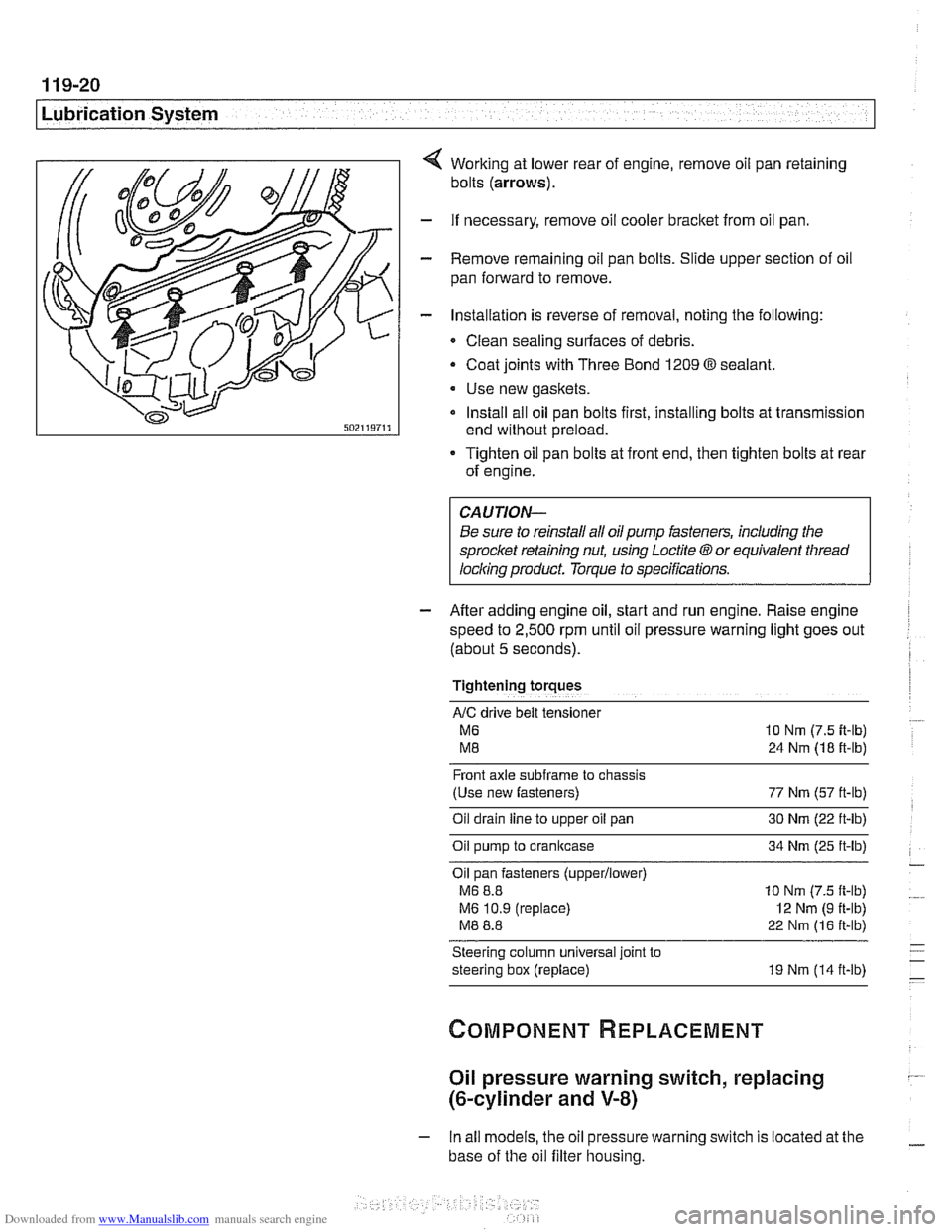
Working at lower rear of engine, remove oil pan retaining
bolts
(arrows).
- If necessary, remove oil cooler bracket from oil pan.
- Remove remaining oil pan bolts. Slide upper section of oil
pan forward to remove.
- Installation is reverse of removal, noting the following:
Clean sealing surfaces of debris.
- Coat joints with Three Bond 1209 O sealant.
Use new gaskets.
Install all oil pan bolts first, installing bolts at transmission
end without preload.
Tighten oil pan bolts at front end, then tighten bolts at rear
of engine.
Be sure to reinstall all oil
pump fasteners, including the
sprocl
speed to
2,500 rpm until oil pressure warning light goes out
(about
5 seconds).
Tightening torques
AIC drive belt tensloner
M6 10 Nm (7.5 it-lb)
M8 24 Nm (18 ft-lb)
Front axle
subframe to chassis
(Use new fasteners) 77 Nm (57 ft-lb)
Oil drain
line to upper oil pan 30 Nm (22 ft-lb)
Oil pump to crankcase 34 Nm (25 ft-lb)
Oil pan fasteners
(upperllower)
M6 8.8 10 Nm (7.5 ft-lb)
M6 10.9 (replace)
I2 Nm (9 ft-lb)
M8 8.8 22 Nm (16 ft-lb)
Steering column universal joint to
steering box (replace) 19 Nm (14 ft-lb)
Oil pressure warning switch, replacing
(&cylinder and V-8)
- In all models, the oil pressure warning switch is located at the
base of the oil filter housing.
Page 343 of 1002
Downloaded from www.Manualslib.com manuals search engine
Lubrication System
- Lower front suspension and remove oil pan, as described
earlier, to gain access to oil pump.
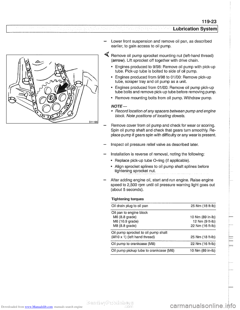
Remove oil pump
sprocket mounting nut (left-hand thread)
(arrow). Lift sprocket off together with drive chain.
Engines produced to 9/98: Remove oil pump with pick-up
tube. Pick-up tube is bolted to side of oil pump.
Engines produced from 9/98 to 01/00: Remove pick-up
tube, scraper tray and oil pump as a unit.
Engines produced from 01/00: Remove oil pump pick-up
tube bolts and remove pick-up tube before removing pump.
Remove mounting bolts from oil pump. Withdraw pump.
NOTE-
Record location of any spacers between pump and engine
bloclc Note positions of locating dowels.
- Remove cover from oil pump and check for wear or scoring.
Spin oil pump shaft and
check that gears turn smoothly. Re-
place pump if gears spin with difficulty
orany wear is present.
- Inspect oil pressure relief valve as described later.
- Installation is reverse of removal, noting the following:
Replace pick-up tube O-ring (if applicable).
- Align sprocket splines to oil pump shaft spl~nes before
tightening sprocket nut.
- After adding engine oil, start and run engine. Raise engine
speed to 2,500 rpm until oil pressure warning light goes out
(about 5 seconds).
Tightening torques Oil drain plug to oil pan 25
Nm (18 ft-lb)
Oil pan to engine
bloclc
M6 (8.8 grade)
M6 (10.9 grade)
M8 (8.8 grade)
10 Nm (89 in-lb)
12
Nrn (9 ft-lb)
22 Nm (16 ft-lb)
Oil pump sprocket to oil pump shait
(M10 x 1) (left hand thread)
25 Nm (1 8 it-lb)
Oil pump to crankcase (ME) 22 Nm (1 6 it-lb)
Oil pump pickup tube to cranltcase (M6) 10 Nm (89 in-lb)
Page 344 of 1002
Downloaded from www.Manualslib.com manuals search engine
11 9-24
Lubrication System
Oil pump, removing and installing (V-8)
CAUTION-
V8 engines: The oil pump fasteners (including the sprocket
retaining nut) are known to vibrate loose. This can result in oil
starvation and engine failure. Be sure to
checlc oil bolts and
nut tighness whenever the oil pump is accessible. If any fas-
teners are found to be loose, remove them and reinstall with
Loctite
8 and torque to specifications.
- Remove upper oil pan, as described earlier, to gain access to
oil pump.
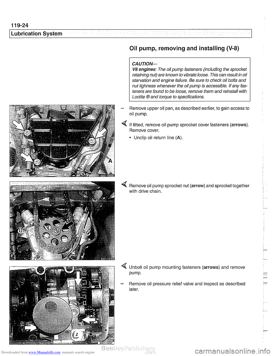
4 If fitted, remove oil pump sprocket cover fasteners (arrows).
Remove cover.
* Unclip oil return line (A).
4 Remove oil pump sprocket nut (arrow) and sprocket together
with drive chain.
Unbolt oil pump mounting fasteners (arrows) and remove
pump.
Remove oil pressure relief valve and inspect as described
later.
Page 346 of 1002
Downloaded from www.Manualslib.com manuals search engine
11 9-26
/Lubrication System
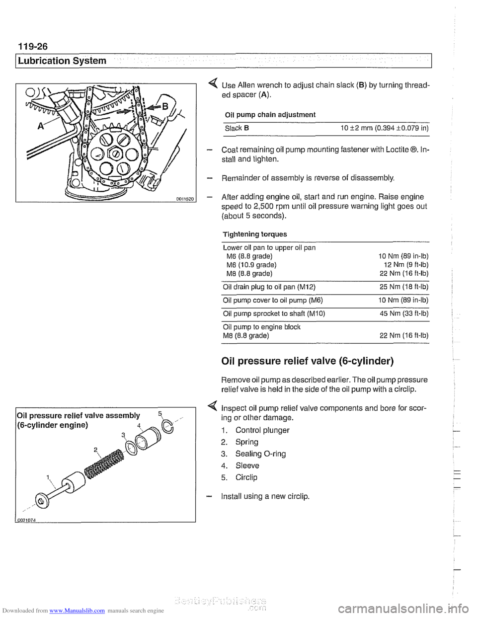
< Use Allen wrench to adjust chain slaclc (B) by turning thread-
ed spacer
(A).
Oil pump chain adjustment
Slack
10 52 mrn (0.394i0.079 in)
- Coat remaining oil pump mounting fastener with Loctite 03. In-
stall and tighten.
- Remainder of assembly is reverse of disassembly.
- After adding engine oil, start and run engine. Raise engine
speed to
2,500 rpm until oil pressure warning light goes out
(about
5 seconds).
Tightening torques
Lower oil pan to upper oil pan
M6 (8.8 grade) 10
Nm (89 in-ib)
M6 (10.9 grade) 12
Nm (9 ft-lb)
M8 (8.8 grade) 22
Nrn (1 6 ft-lb)
Oil drain plug to oil pan (M12) 25 Nm (I8 ft-lb)
Oil pump cover to oil pump
(M6) 10 Nrn (89 in-lb)
Oilpump sprocket to shaft TKO) 45 Nm (33 it-lb)
Oil pump to engine bloclc
M8 (8.8 grade) 22 Nrn (16 ft-lb)
Oil pressure relief valve (&cylinder)
Remove oil
pump as described earlier. The oil pump pressure
relief valve is held in the side of the
oil pump with a circlip.
< Inspect oil pump relief valve components and bore for scor-
4. Sleeve
5. Circlip
- Install using a new circlip.
Oil
pressure relief valve assembly
,- ..., !~. -.-~. - ~- -~!~~-% h. .- .,, /to-cy~~noer engrnej ing or other damage.
1. Control plunger
2. Spring
3. Sealing O-ring
Page 347 of 1002
Downloaded from www.Manualslib.com manuals search engine
11 9-27
Lubrication System
Oil pressure relief valve (V-8)
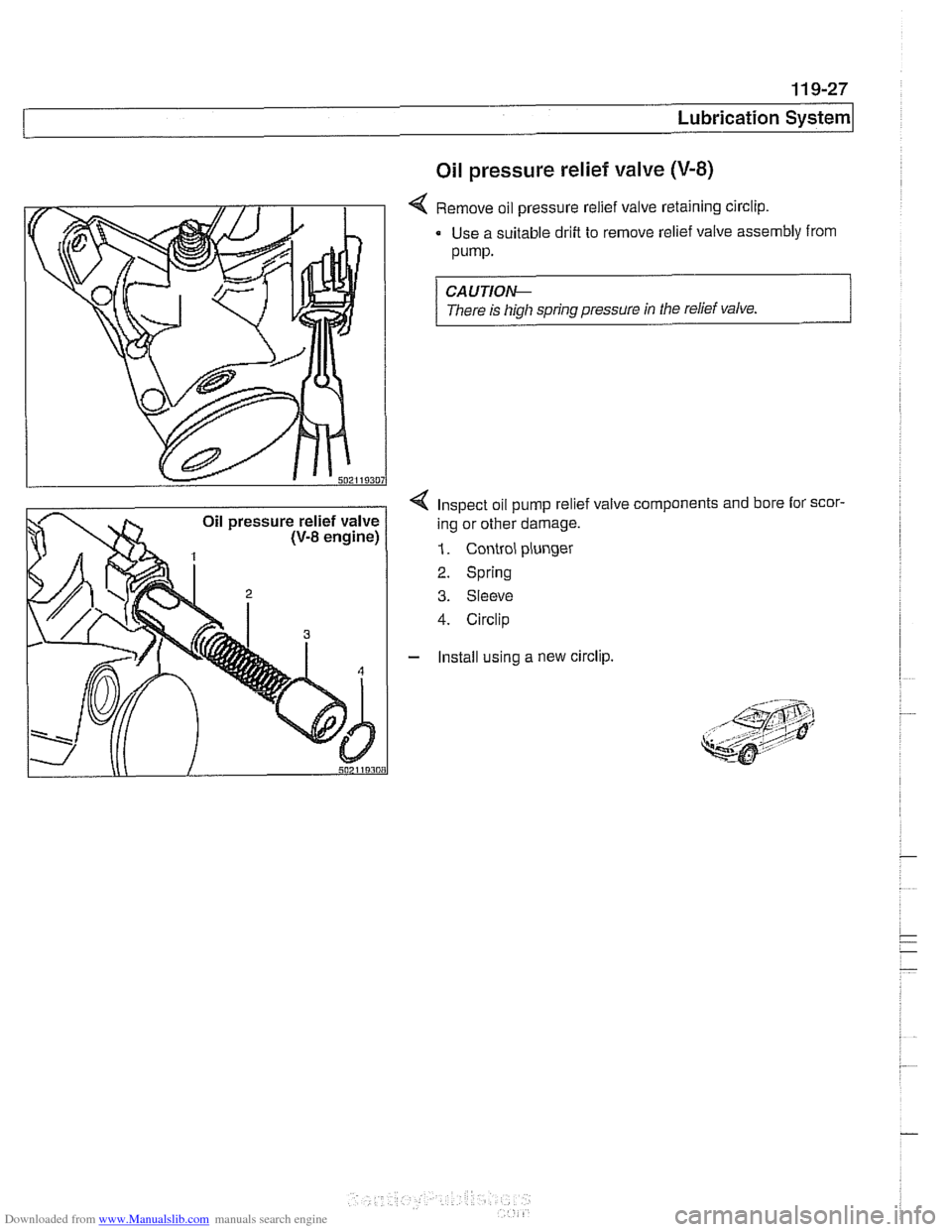
4 Remove oil pressure relief valve retaining circlip.
Use a suitable drift to remove relief valve assembly from
pump.
CAUTION--
There is high spring pressure in the relief valve.
4 Inspect oil pump relief valve components and bore lor scor-
ing or other damage.
1. Control plunger
2. Spring
3. Sleeve
4. Circlip
- Install using a new circlip.
Page 349 of 1002
Downloaded from www.Manualslib.com manuals search engine
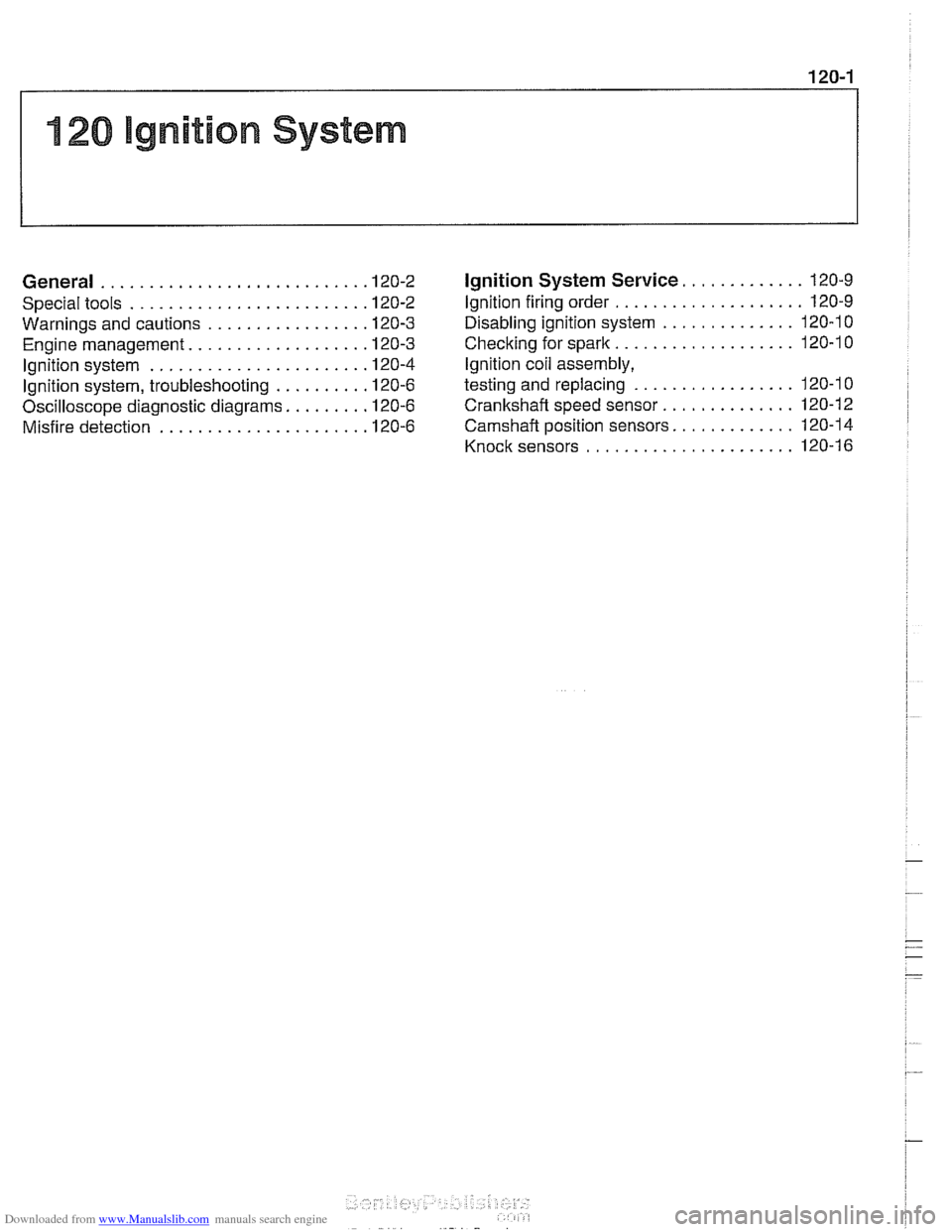
120 lgnition System
...................... General
Special tools ...................
Warnings and cautions ...........
Engine management .............
................. lgnition system
Ignition system. troubleshooting
....
... Oscilloscope diagnostic diagrams
................ Misfire detection
............. Ignition System Service 120-9
.................... Ignition firing order 120-9
.............. Disabling ignition system 120-10
................... Checking for spark 120-1 0
lgnition coil assembly.
................. testing and replacing 120-1 0
.............. Crankshaftspeedsensor 120-12
............. Camshaft position sensors 120-1 4
...................... Knocksensors 120-16
Page 350 of 1002
Downloaded from www.Manualslib.com manuals search engine
Ignition System
This repair group covers component troubleshooting and re-
placement information for the ignition system.
When diagnosing engine management problems, including
on-board diagnostics (OBD
11) fault code analysis, also refer
to these repair groups:
* 130 Fuel Injection
* ELE Electrical Wiring Diagrams
OED On-Board Diagnostics
Special tools
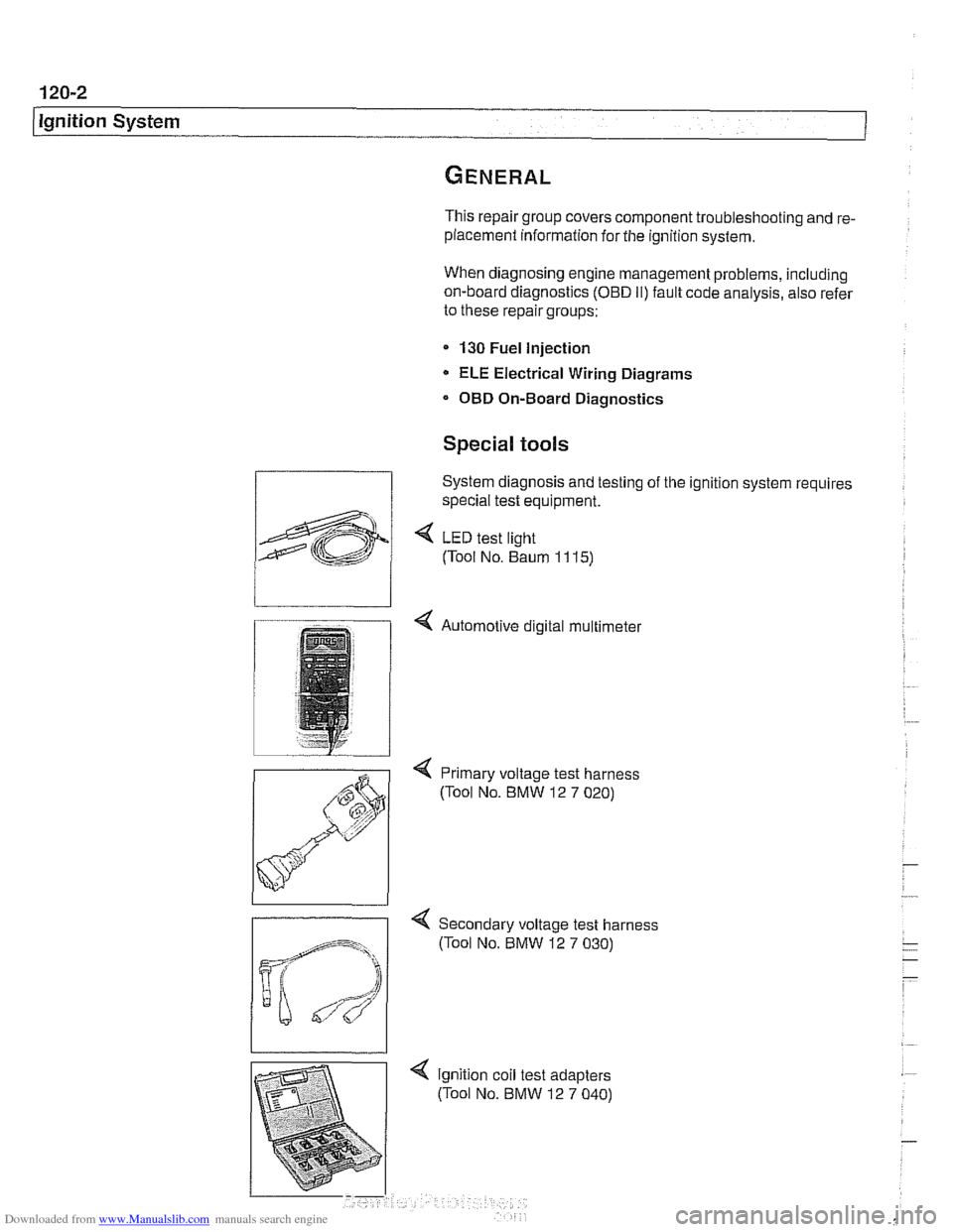
System diagnosis and testing of the ignition system requires
special test equipment.
4 LED test light
(Tool No. Baum
1 1 15)
4 Automotive digital multimeter
4 Primary voltage test harness
(Tool No. BMW 12
7 020)
-
4 Secondary voltage test harness
(Tool No. BMW 12
7 030)
Page 351 of 1002
Downloaded from www.Manualslib.com manuals search engine
120-3
Ignition System
Warnings and cautions
The ignition system produces dangerous high voltage. In ad-
dition the sensitive electronic components can be damaged
if
proper precautions are not adhered to.
WARNING-
* Do not touch or disconnect any cables from the coils while
the engine is running or being
cranked by the starter.
The ignition system produces high voltages that can be
fatal. Avoid contact with exposed terminals. Use ex-
treme caution when working on a car with the ignition
switched on or the engine running.
- Connect and disconnect tlie DME system wiring and
test equipment leads only when the ignition is
OFF:
Before operating the starter without starting the engine
(for example when
making a compression test) always
disable the ignition.
CA
U TIOW-
Do not attempt to disable the ignition by removing the coils
from the spark plugs.
Connect or disconnect ignition system wires, multiple
wire connectors, and ignition test equipment leads only
while the ignition is
off Switch multimeter functions or
measurement ranges only with the test probes discon-
nected.
* Do not disconnect the battery while the engine is run-
ning.
A high impedance digital multimeter should be used for
all voltage and resistance tests. An LED test light
should be used in place of an incandescent-type test
lamp.
In general, make test connections only as specified by
BMW as described in this manual, or as described by
the instrument manufacturer.
Engine management
BMW €39 engines use an advanced engine management
system known as Digital Motor Electronics (DME). DME in-
corporates on-board diagnostics, fuel injection, ignition and
other engine control functions. DME variants are listed in
Table a. Engine management systems.
Second generation On-Board Diagnostics
(OED II) is incor-
porated into the engine management systems used on the
cars covered by this manual. Use a BMW-specific electronic
scan tool, or a "Generic"
OED II scan tool to access Diagnos-
tic Trouble Codes (DTCs). DTCs can help pinpoint ignition
ine management problems.