130 BMW 528i 1998 E39 Owner's Guide
[x] Cancel search | Manufacturer: BMW, Model Year: 1998, Model line: 528i, Model: BMW 528i 1998 E39Pages: 1002
Page 458 of 1002
Downloaded from www.Manualslib.com manuals search engine
130-68
Fuel Injection
0
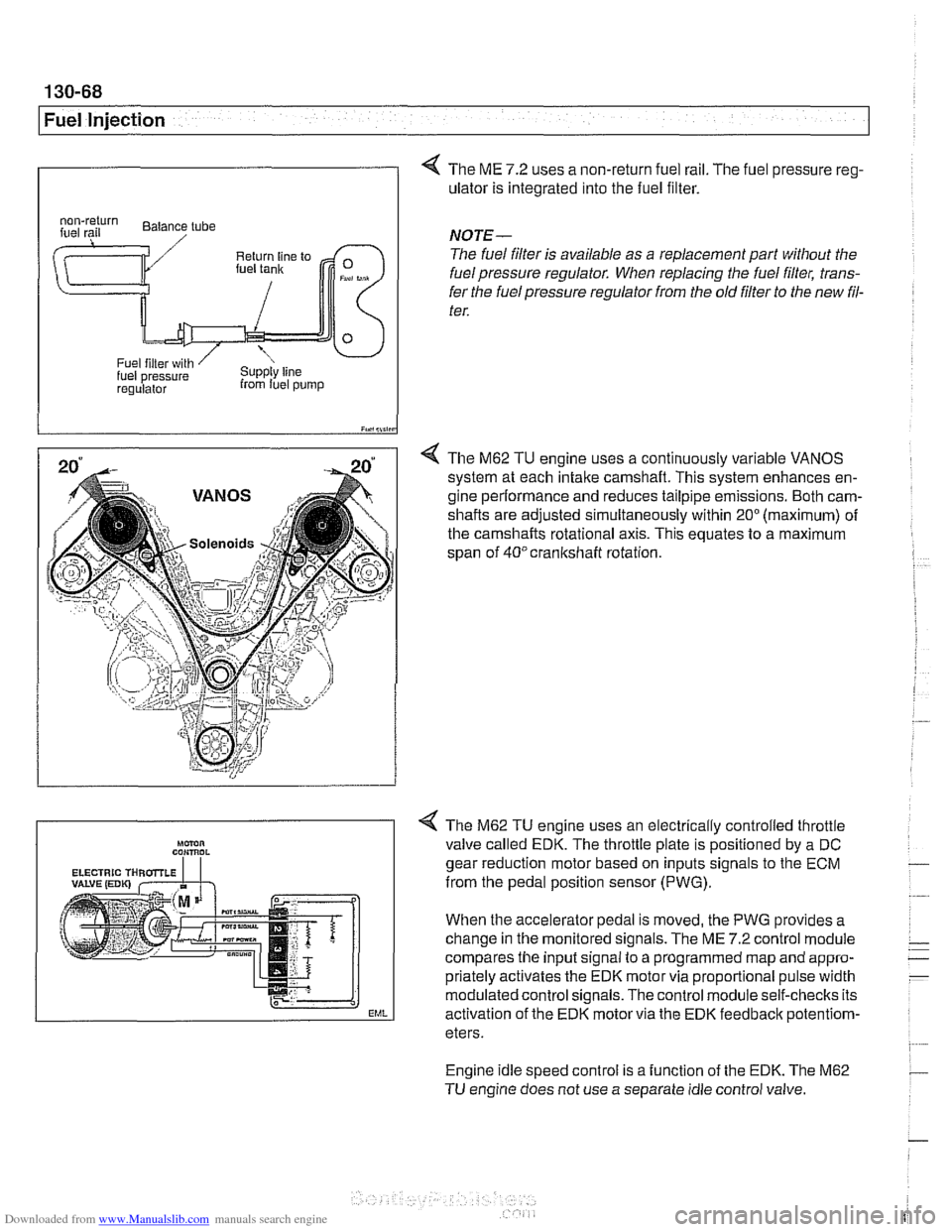
4 The ME 7.2 uses a non-return fuel rail. The fuel pressure reg-
ulator is integrated into the fuel filter.
I iY.,lii,in
4 The M62 TU engine uses a continuously variable VANOS
system at each intake camshaft. This system enhances en-
gine performance and reduces tailpipe emissions. Both cam-
shafts are adjusted simultaneously within
20" (maximum) of
the camshafts rotational axis. This equates to a maximum
span of
40°crankshaft rotation.
regulalor from luel pump
NOTE-
The fuel filter is available as a replacement part without the
fuel pressure regulator. When replacing the fuel filter, trans-
fer the fuel pressure regulator from the old
filter to the new fil-
ter.
Engine idle speed control is a function of the EDK. The M62
TU engine does not use a separate idle control valve.
Mmn CON,ROL
EML
< The M62 TU engine uses an electrically controlled throttle
valve called EDK. The throttle plate is positioned by a DC
gear reduction motor based on inputs signals to the ECM
from the pedal position sensor (PWG).
When the accelerator pedal is moved, the PWG provides a
change in the monitored signals. The ME
7.2 control module
compares the input signal to a programmed map and appro-
priately activates the EDK motor via proportional pulse width
modulated control signals. The control module self-checks its
activation of the EDK motor via the EDK feedbaclc
potentiom-
eters.
Page 460 of 1002
Downloaded from www.Manualslib.com manuals search engine
130-70
Fuel Injection
ECM relay
--
CAUTION-
Relay positions can vary Be sure to confirm relay position by
identifying the wiring in the
socl(et using the wiring diagrams
in ELE Electrical Wiring Diagrams.
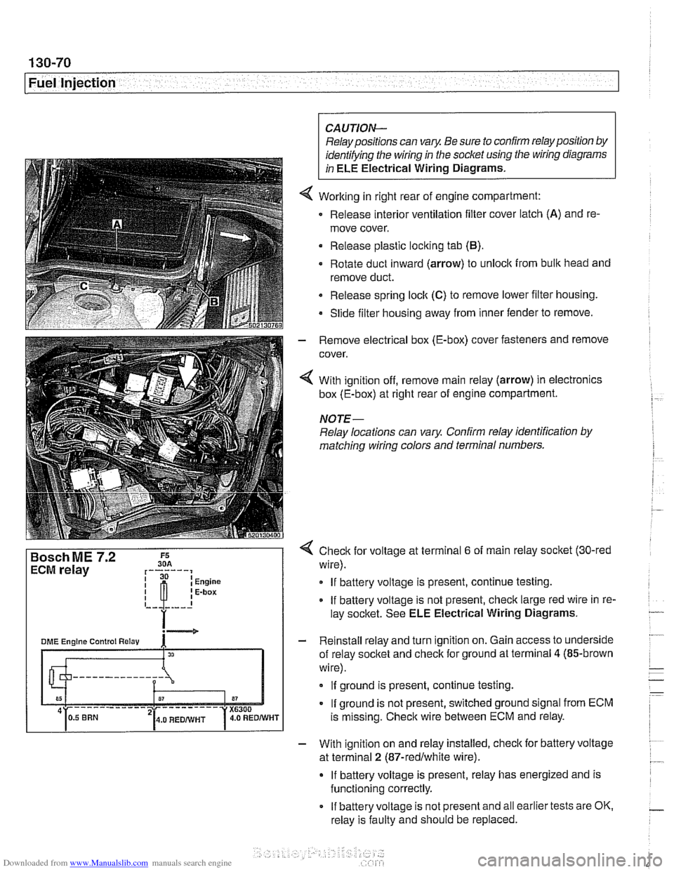
Working in right rear of engine compartment:
Release interior ventilation filter cover latch
(A) and re-
move cover.
Release plastic locking tab
(B).
Rotate duct inward (arrow) to unlock from bulk head and
remove duct.
Release spring
loclt (C) to remove lower filter housing.
Slide filter housing away from inner fender to remove.
- Remove electrical box (E-box) cover fasteners and remove
cover.
4 With ignition off, remove main relay (arrow) in electronics
box (E-box) at right rear of engine compartment.
NOTE-
Relay locations can vary Confirm relay identification by
matching wiring colors and terminal numbers.
4 Check for voltage at terminal 6 of main relay socket (30-red
wire).
If battery voltage is present, continue testing.
If battery voltage is not present, check large red wire in re-
lay socltet. See ELE Electrical Wiring Diagrams.
- Reinstall relay and turn ignition on. Gain access to underside
of relay socket and check for ground at terminal
4 (85-brown
wire).
If ground is present, continue testing.
If ground is not present, switched ground signal from ECM
is missing. Check wire between ECM and relay.
- With ignition on and relay installed, check for battery voltage
at terminal
2 (87-redlwhite wire).
If battery voltage is present, relay has energized and is
functioning correctly.
If battery voltage is not present and all earlier tests are OK.
relay is faulty and should be replaced.
Page 462 of 1002
Downloaded from www.Manualslib.com manuals search engine
130-72
Fuel Injection
I Oxygen sensors, replacing
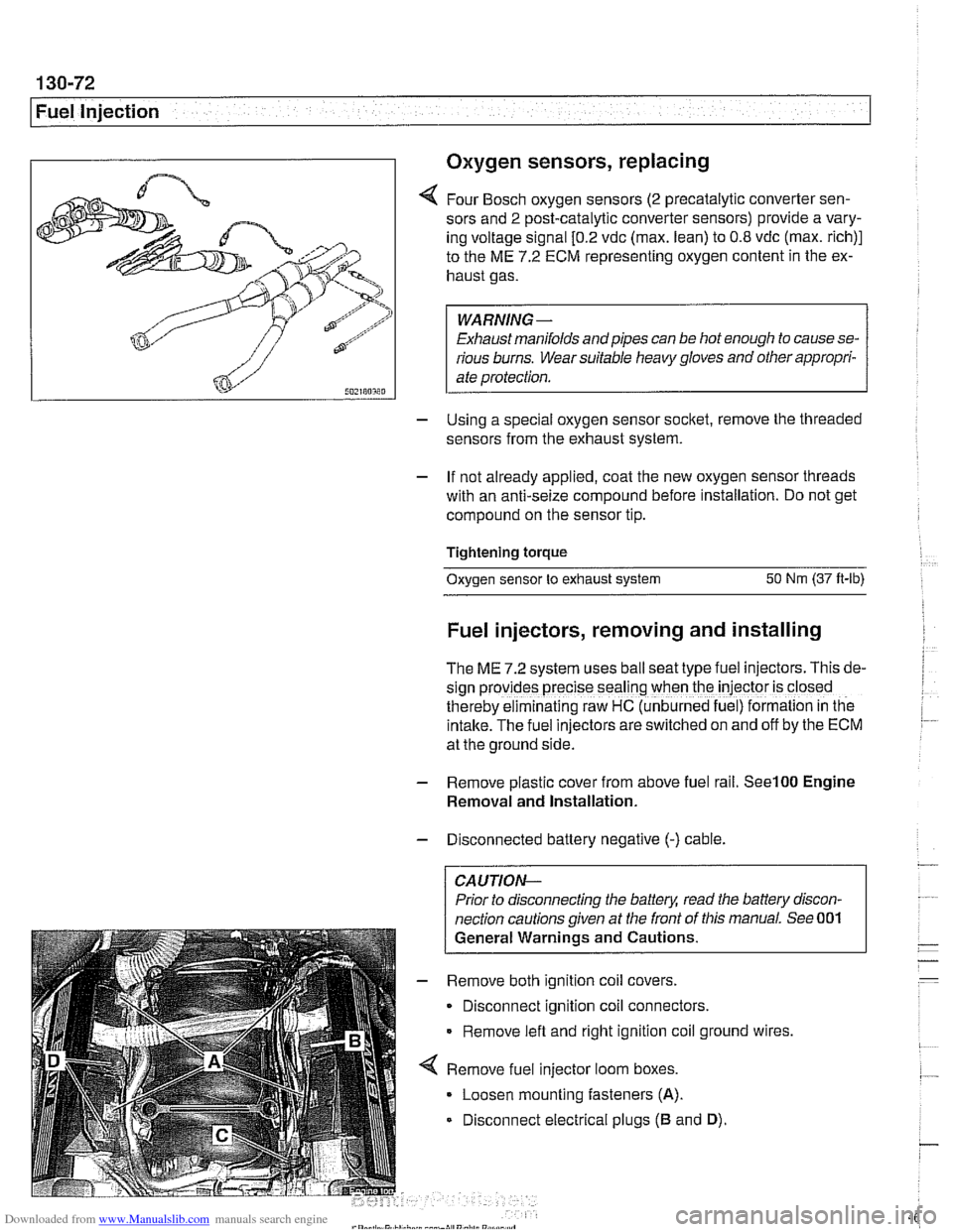
4 Four Bosch oxygen sensors (2 precatalytic converter sen-
sors and
2 post-catalytic converter sensors) provide a vary-
ing voltage signal
[0.2 vdc (max. lean) to 0.8 vdc (max. rich)]
to the ME
7.2 ECM representing oxygen content in the ex-
haust gas.
WARNING-
Exhaust manifolds and pipes can be hot enough to cause se-
rious burns. Wear suitable heavy gloves and other appropri-
ate protection.
- Using a special oxygen sensor socltet, remove the threaded
sensors from the exhaust system.
- If not already applied, coat the new oxygen sensor threads
with an anti-seize compound before installation. Do not get
compound on the sensor tip.
Tightening torque
Oxygen sensor to exhaust system
50 Nm (37 ft-lb)
Fuel injectors, removing and installing
The ME 7.2 system uses ball seat type fuel injectors. This de-
sign
prov:des precise seal'ng when the iniector is closed
therebv eiminalinq raw HC (unb~rned fue ) formalion in tne
intake.-~he fuel inkctors areswitched on and off by the ECM
at the ground side.
- Remove plastic cover from above fuel rail. See100 Engine
Removal and Installation.
- Disconnected battery negative (-) cable.
CAUTION-
Prior to disconnecting the battea read the battery discon-
nection cautions given at the front of this manual. See 001
General Warnings and Cautions.
- Remove both ignition coil covers.
Disconnect ignition coil connectors.
Remove left and right ignition coil ground wires,
4 Remove fuel injector loom boxes.
Loosen mounting fasteners
(A).
Disconnect electrical plugs (B and D).
Page 464 of 1002
Downloaded from www.Manualslib.com manuals search engine
130-74
I Fuel Injection
Evaporative system pressure leak
diagnosis, overview
The M62 TU engine is equipped wlth an evaporative fuel sys-
tem pressure leak diagnosis system. The main component of
this system is the leakdiagnosis pump (LDP). The function of
the LDP is to pressurize the fuel tank and the evaporative
emission system for the purpose of detecting leaks.
This system iscapable of detecting a
lealcas small as0.5 mm.
The LDP, located in the left rear wheel housing, contains the
following:
Vacuum chamber. Pneumatic pump chamber
DME activated vacuum solenoid
Reed switch (provides switched voltage
feedback signal to
DME).
The vacuum supply line is in the wiring harness from the en-
gine compartment and runs down the driver's side of the vehi-
cle.
The canister vent valve is
~ntegrated into the LDP, which IS
electrically controlled by the ECM. The canister vent valve is
opened to provide fresh air entry into the fuel system only dur-
ing purge operation.
- Purge operation characteristics:
Off idle through full throttle: purge valve opened by pulse
width modulated (PWM) control of the ECM. PWM duty cy-
cle varies by engine operating conditions
(e.g. warm idle,
purge valve opened slightly; cold
idleldecel with engine
temp
< 67" C. purge valve always closed).
Page 465 of 1002
Downloaded from www.Manualslib.com manuals search engine
130-75
Fuel Injection
Secondary air injection, overview
The secondary air system pumps ambient air into the exhaust
stream afteracoid engine start to reduce the warm-up time of
the catalytic converters and to reduces HC and CO emis-
sions. The ME
7.2 ECM controls and monitors the secondary
air injection system. The secondary air pump operates at a
starttemperature of between 10°C
(50°F) and 40°C (104°F).
and continues to operate for a maximum of
2 minutes at idle
speed.
The electric air pump draws in ambient air and supplies it to
the
checlc valve. The vacuum vent valve (solenoid) switches
vacuum to open the
checlc valve when activated by the ECM.
Once opened, the checlc
valve allows air to be pumped into
the exhaust stream.
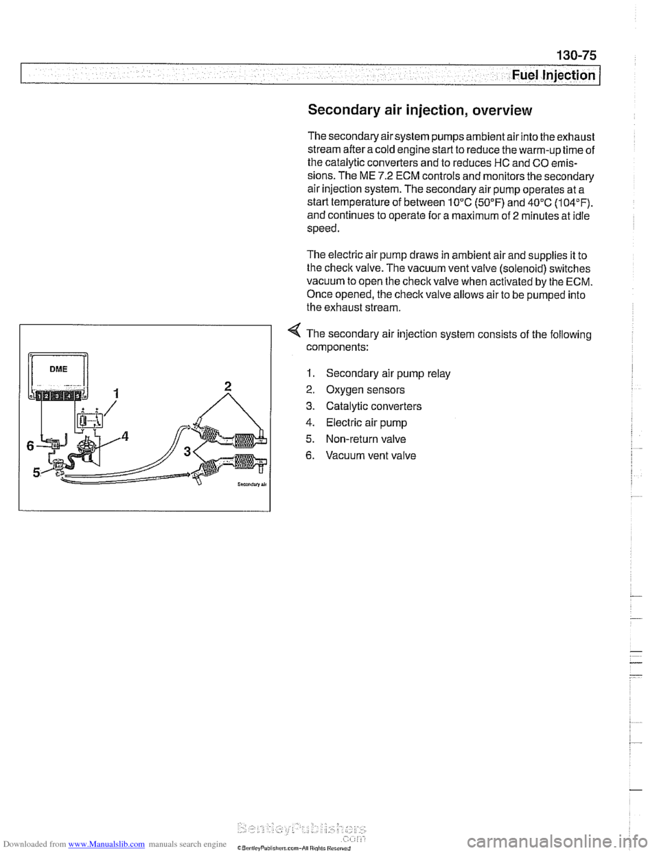
4 The secondary air injection system consists of the following
components:
1. Secondary air pump relay
2. Oxygen sensors
3. Catalytic converters
4. Electric air pump
5. Non-return valve
6. Vacuum vent valve
Page 466 of 1002
Downloaded from www.Manualslib.com manuals search engine
130-76
Fuel Injection
Bosch
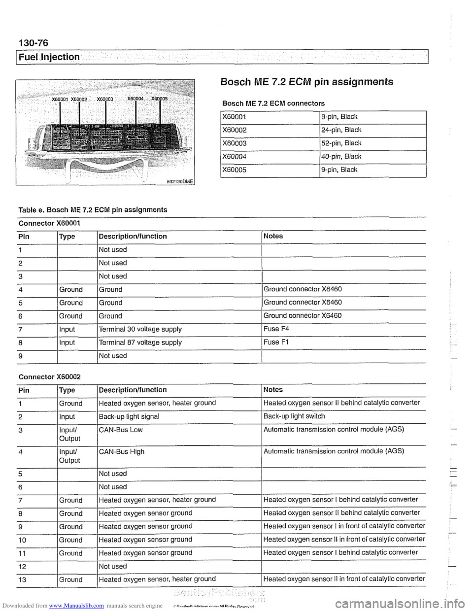
ME 7.2 ECM pin assignments
Bosch ME 7.2 ECM connectors
X60001
X60002
X60003
X60004
X60005
Table e. Bosch ME 7.2 ECM pin assignments
Connector
X60001
I I I
8 1 lnput [Terminal 87 voltage supply I Fuse F1
9-pin, Black
24-pin, Black
52-pin, Black
40-pin, Black
9-pin,
Blaclc
I I I
9 I NO^ used I
Notes
Ground connector
X6460
Ground connector X6460
Pin 1
2 3
4
5
Connector X60002
Ground connector X6460 6
Pin
/Type I Descriptionlfunction 1 Notes
Type
Ground
Ground
7 llnput l~errninai 30 voltage supply I Fuse F4
Descriptionlfunction
Not used
Not used
Not used
Ground Ground
Ground Ground
1
2
3
4
5
6
7
8
9
10
11
12
13
. . - Ground Input
Input/
output
input/
Output
Ground
Ground
Ground
Ground
Ground
Ground Heated oxygen sensor, heater ground
Back-up
light signal
CAN-BUS Low
CAN-Bus High
Not used Not used
Heated oxygen sensor, heater ground
Heated oxygen sensor ground
Heated oxygen sensor ground
Heated oxygen sensor ground
Heated oxygen sensor ground
Not used
Heated oxvaen sensor, heater
ground
Heated oxygen sensor II behind catalylic converter
Baclcup light switch
Automatic transmission control module (AGS)
Automatic transmission control module (AGS)
Heated oxygen sensor
I behind catalytic converter
Heated oxygen sensor
II behind catalytic converter
Heated oxygen sensor I in front of catalytic converter
Heated oxygen sensor
II in front of catalytic converter
Heated oxygen sensor
I behind catalytic converter
Heated oxygen sensor
Ii in front of catalytic converter
Page 472 of 1002
Downloaded from www.Manualslib.com manuals search engine
This repair group covers service information specifically for the fuel supply system. Information on the fuel injection sys-
tem is covered in
130 Fuel Injection.
In the descriptions and procedures given below, engine and
engine management (DME) systems are referred to by man-
ufacturer code. If necessary, see
100 Engine-General for
model year, engine code, and DME applications.
NOTE-
Fuel filter replacement is covered in 020 Maintenance,
Special tools
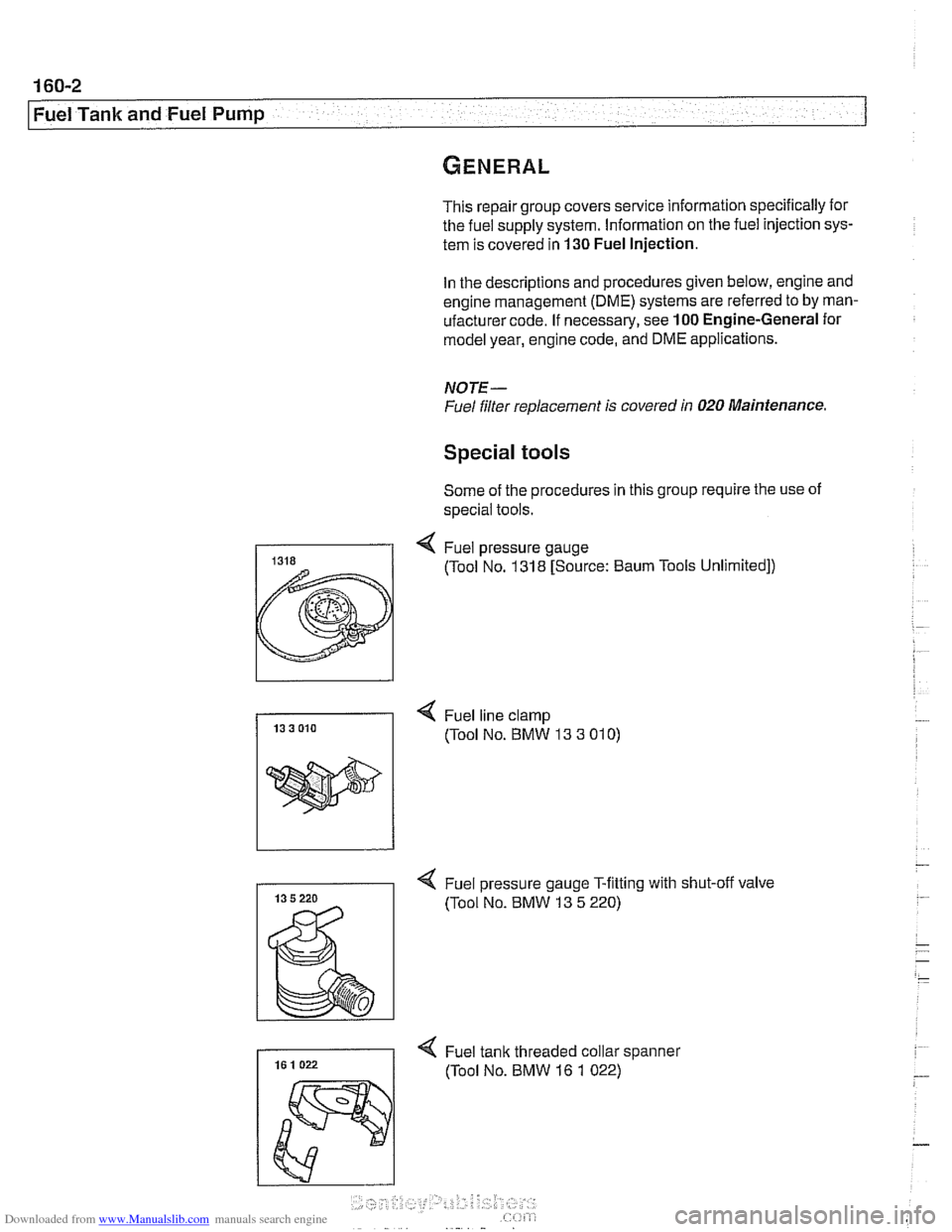
Some of the procedures in this group require the use of
special tools.
I( Fuel line clamp 13 3 010 (Tool No. BMW 13 3 01 0)
4 Fuel pressure gauge T-fitting with shut-off valve
(Tool No. BMW 13
5 220)
Page 473 of 1002
Downloaded from www.Manualslib.com manuals search engine
Fuel Tank and Fuel Pump
Fuel pump
The electric fuel pump is mounted in the fuel tank in tandem
with the right side fuel level sender. The fuel pump delivers
pressurized fuel to the fuel injection system.
A pressure regu-
lator maintains system pressure. The quantity of fuel supplied
exceeds demand, so excess fuel returns to the fuel tank via a
return line. See
130 Fuel Injection for more information.
NOTE-
Fuel pump removal procedures are given under Fuel level
sender (right side) and fuel pump, removing and install-
ing.
Fuel tank evaporative control system
Evaporative control, also referred to as running losses con-
trol, is designed to prevent fuel system evaporative losses
from venting into the atmosphere.
The components of this system allow control and monitoring
of evaporative losses by the on-board diagnostic
(OED II)
software incorporated into the engine control module (ECM).
NOTE-
1997 V-8 models (540i) with Bosch DME M5.2 are not
equipped with an
OBD I1 running losses monitoring system.
Fuel tank evaporative
control system
(models with
DME MS42.0)
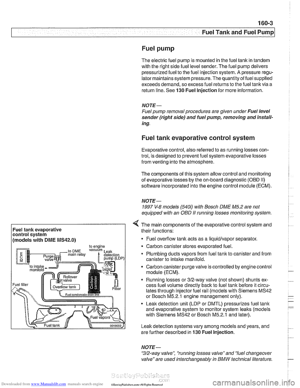
4 The main components of the evaporative control system and
their functions:
Fuel overflow
tank acts as a liquidlvapor separator
Carbon canister stores evaporated fuel.
Plumbing ducts vapors from fuel tank to canister and from
canister to intake
manifold.
- Carbon canister purge valve is controlled by enginecontrol
module (ECM).
Running losses or 312-way valve (not shown) shunts ex-
cess fuel volume directly
back to fuel tank before it circu-
lates through injector fuel rail (models with Siemens MS42
or Bosch M5.2.1 engine management only).
Leak detection unit (LDP or DMTL) pressurizes fuel
tank
and evaporative system to monitor system leaks (models
with Siemens MS42 or Bosch M5.2.1 and later).
Leak detection systems vary among models and years, and
are further described in
130 Fuel Injection.
NOTE -
"3/2-way valve", 'tunning losses valve" and "fuel changeover
valve" are used interchangeably
in BMW technical literature.
Page 490 of 1002
Downloaded from www.Manualslib.com manuals search engine
--
I Fuel Tank and Fuel Pump
The plastic fuel tank is mounted underneath the center of the
car (underneath the rear seat). Mounted in the fuel tank are
the fuel pump and fuel level sending units. Connecting lines
for the evaporative emission control system and expansion
tank are also attached to the tank.
Fuel
tank capacity for E39 models
Tank capacity
70 liters (18.5 gal)
Reserve capacity
8 liters (2.1 gal)
Fuel tank, draining
Drain fuel tank into a safe storage unit using an approved fuel
pumping device.
WARNING-
# Before removing tank, be sure that all hot components,
such as the exhaust system, are completely cooled down.
Fuel may be spilled. Do not smoke or
work near heat-
ers or other fire hazards.
- Start engine and allow to run 10 - 15 seconds to fill fuel com-
pensating siphon assembly. This will allow both lobes of fuel
tank to he drawn off through fuel filler pipe,
- Disconnect negative cable from battery.
CAUTION-
Prior to disconnecting the batteg read the battery discon-
nection cautions given
in 001 General Warnings and Cau-
tions.
- Remove fuel tank filler cap
- Slide suction hose into filler neck about 130 cm (51 in.), twist-
ing as necessary. Withdraw fuel into storage unit.
- Monitor fuel level reduction in both lobes:
- Remove rear seat cushion and access both fuel tank send-
er harness connectors.
Use multimeter to measure resistance at both senders,
Resistance should drop as fuel level drops.
- If siphoning mechanism is faulty, drain left tank lobe sepa-
rately by removing sender cover and pumping fuel directly
out of left lobe.
Page 545 of 1002
Downloaded from www.Manualslib.com manuals search engine
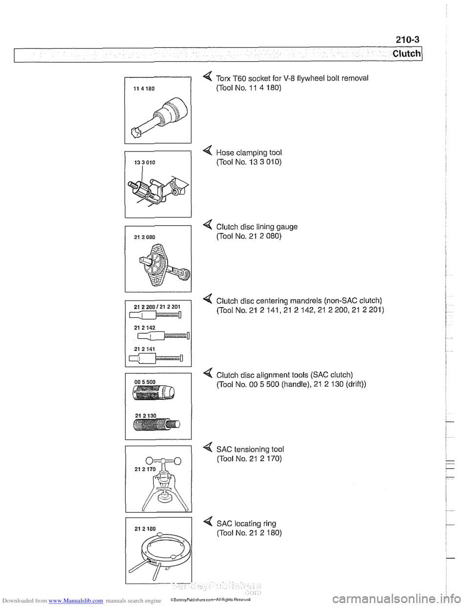
4 Tom T60 socket for V-8 flywheel bolt removal
(Tool No. 1 1 4 180)
4 Hose clamping tool
(Tool No. 13 3
01 0)
4 Clutch disc lining gauge
(Tool No. 21 2 080)
4 Clutch disc centering mandrels (non-SAC clutch)
(Tool No. 21 2
141,21 2 142,21 2 200,21 2 201)
4 Clutch disc alignment tools (SAC clutch)
(Tool No. 00 5 500 (handle). 21 2 130 (drift))
4 SAC tensioning tool
(Tool No. 21 2 170)
4 SAC locating ring
(Tool No. 21 2 180)