ECT BMW 528i 1998 E39 Workshop Manual
[x] Cancel search | Manufacturer: BMW, Model Year: 1998, Model line: 528i, Model: BMW 528i 1998 E39Pages: 1002
Page 743 of 1002
Downloaded from www.Manualslib.com manuals search engine
330-47
Rear suspension/
Ride height sensor, removing and installing
Hall effect sensors for vehicle height detection are mounted
on the
left and right sides of the rear suspension. A coupling
rod mounted between the rear suspension arm and the sen-
sor arm is used to send a varying voltage signal to the
EHC
control module.
Raise car and support safely.
WARNING-
Male sure the car is firmly supported on jaclc stands de-
signed
for the purpose. Place jaclc stands underneath struc-
tural chassis points. Do not place jaclc stands under
sus~ension Darts.
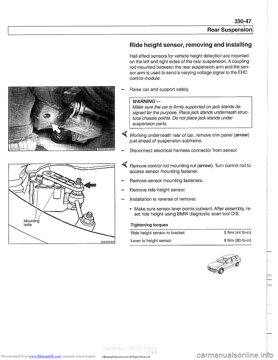
Working underneath rear of car, remove trim panel (arrow)
just ahead of suspension subframe.
Disconnect electrical harness connector from sensor.
4 Remove control rod mounting nut (arrow).Turn control rod to
access sensor mounting fastener.
- Remove sensor mounting fasteners.
- Remove ride height sensor.
- Installation is reverse of removal.
Make sure sensor lever points outward. After assembly, re-
set ride height using BMW diagnostic scan tool DIS.
Tightening torques
Ride
height sensor to bracket 5 Nrn (44 lb-in)
Lever to height sensor
9 Nrn (80 ib-in)
Page 748 of 1002
Downloaded from www.Manualslib.com manuals search engine
331-4
Final Drive
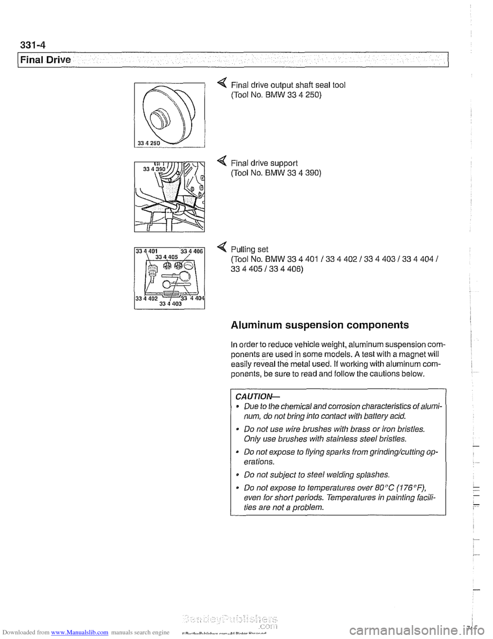
4 Final drive output shaft seal tool
(Tool No.
BMW 33 4 250)
4 Pulling set
(Tool No.
BMW 33 4 401 / 33 4 402 / 33 4 403 133 4 404 /
33 4 405 / 33 4 406)
Aluminum suspension components
In order to reduce vehicle weight, aluminum suspension com-
ponents are
~sed in some models. A tesl wlh a magnet wi.1
eas'ly reveal lhe metal Lseo. If working with a umin~m com-
ponents, be sure to read and follow the cautions below.
CAUTIOI\C
Due to the chemical and corrosion characteristics of alumi-
num, do not bring into contact with battery acid.
Do not use wire brushes with brass or iron bristles.
Only use brushes with stainless steel bristles.
Do not expose to flying sparks from grinding/cutting op-
erations.
Do not subject to steel welding splashes.
Do not expose to temperatures over
80°C (176"F),
even for short periods. Temperatures in painting facili-
ties are not a problem.
Page 749 of 1002
Downloaded from www.Manualslib.com manuals search engine
Final Drive
Final drive, removing and installing
- Raise rear of car.
WARNING-
Make sure that the car is firmly supported on jack stands de-
signed for the purpose. Place the jaclc stands beneath struc-
tural chassis
~oints. Do not i lace iaclc stands under
( suspension barfs.
Remove exhaust system. See 180 Exhaust System.
Disconnect drive shaft from final drive. See
260 Driveshaft.
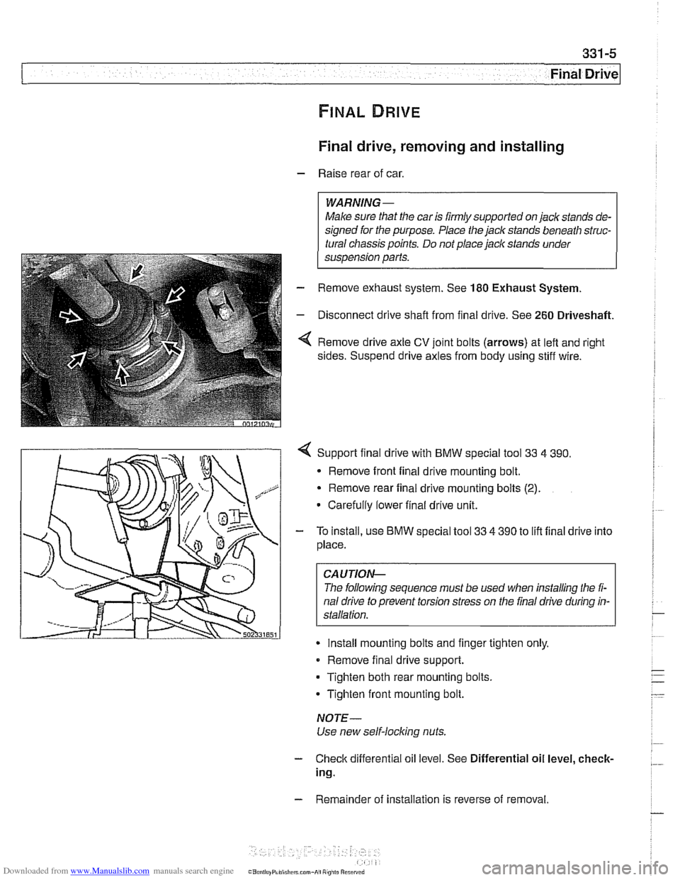
Remove drive axle CV joint bolts (arrows) at left and right
sides. Suspend drive axles from body using stiff wire.
4 Support final drive with BMW special tool 33 4 390.
* Remove front final drive mounting bolt.
Remove rear final drive mounting bolts
(2).
Carefully lower final drive unit.
- To install, use BMW special tool 33 4 390 to lift final drive into
place.
CA UTIOP&
The following sequence must be used when installing the fi-
nal drive to prevent torsion stress on the final drive during in-
Install mounting bolts and finger tighten only.
Remove final drive support.
Tighten both rear mounting bolts.
Tighten front mounting bolt.
NOTE-
Use new self-locking nuts.
- Check differential oil level. See Differential oil level, check-
ing.
- Remainder of installation is reverse of removal.
Page 750 of 1002
Downloaded from www.Manualslib.com manuals search engine
Final Drive
Tightening torques
F~nal drive to rear axle carrier 105 Nm (77 it-lb)
Driveshaft CV joint to final drive flange
- MlO (Torx bolt) 70
Nm (51 ft-lb)
- M8 (compression nut) 32 Nm (24
ft-lb)
Drive axle to final drive
ilange
Torx bolts (M10) 83 Nm (61 ft-lb)
Torx bolt with
rlbbed teeth (M10) 64 Nm (47 ft-lb)
Torx bolt
wlth ribbed teeth (MI0 sliver) 80 Nm (59 ft-lb)
Torx
bolt with ribbed teeth (M10 black) 100 Nm (74 ft-lb)
* Torx bolt with ribbed teeth (M12) 135 Nm (100 ft-lb)
Differential oil level, checking
The E39 differential is filled with lifetime oil that ordinarily
does not need to be changed. BMW recommends using only
a specially formulated synthetic gear oil
(SAF-XO) that is
available through an authorized BMW dealer parts depart-
ment. For additional information on this lubricant and any oth-
er lubricants that may be compatible, contact an authorized
BMW dealer service department.
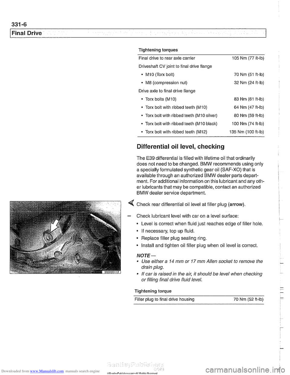
< Check rear differential oil level at filler plug (arrow).
- Check lubricant level with car on a level surface:
Level is correct when fluid just reaches edge of filler hole.
If necessary, top up fluid.
* Replace filler plug sealing ring.
Install and tighten oil filler plug when oil level is correct.
NOTE-
Use either a 14 mm or 17 mm Allen socket to remove the
drain plug.
If car is raised in the air. it should be level when
checkino " or filling final drive fluid level.
- Tightening torque -
Filler plug to final drive housing 70 Nm (52
ft-lb) -
Page 759 of 1002
Downloaded from www.Manualslib.com manuals search engine
Final ~rivel
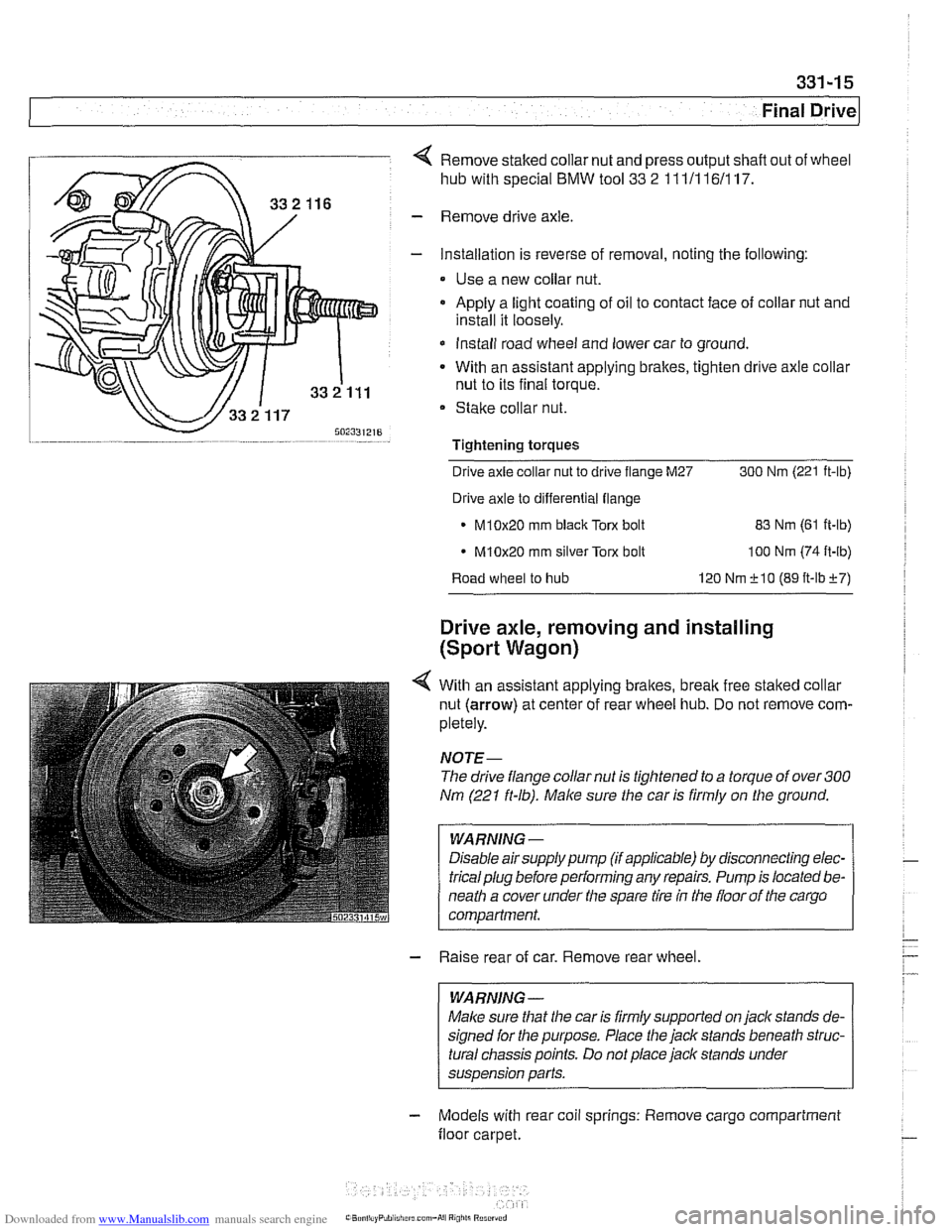
4 Remove staked collar nut and press output shafl out of wheel
hub with special
BMW tool 33 2 111/116/117.
- Remove drive axle.
- Installation is reverse of removal, noting the following:
Use a new collar nut.
a Apply a light coating of oil to contact face of collar nut and
install it loosely.
* Install road wheel and lower car to ground.
- With an assistant applying brakes, tighten drive axle collar
nut to its final torque.
Stake collar nut.
Tightening torques
-
Drive axle collar nut to drive flange M27 300 Nrn (221 ft-lb)
Drive axle to differential flange
* M10x20 rnm black Torx bolt
83 Nrn (61 ft-lb)
M10x20 rnrn silver Torx bolt
100 Nrn (74 ft-lb)
Road wheel to hub 120 Nrn f 10 (89 ft-lbf7)
Drive axle, removing and installing
(Sport Wagon)
4 With an assistant applying brakes, brealc free staked collar
nut (arrow) at center of rear wheel hub. Do not remove com-
pletely.
NOJE-
The drive flange collar nut is tightened to a torque of over 300
Nm (221 ft-lb). Make sure the car is firmly on the ground.
WARNING -
Disable airsupply pump (if applicable) by disconnecting elec-
tricalplug before performing any repairs. Pump is located be-
neath a cover under the spare tire
in the floor of the cargo
compartment.
- Raise rear of car. Remove rear wheel.
WARNING -
Malce sure that the car is firmly supported on jack stands de-
signed for the purpose. Place the jack stands beneath struc-
tural chassis points. Do not place jack stands under
suspension parts.
- Models with rear coil springs: Remove cargo compartment
floor carpet.
Page 761 of 1002
Downloaded from www.Manualslib.com manuals search engine
331-17
Final ~rivel
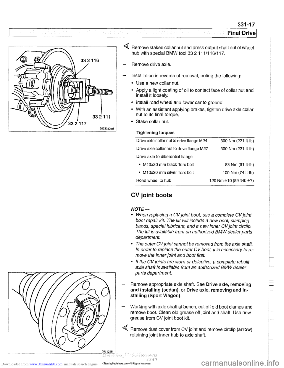
4 Remove staked collar nut and press output shaft out of wheel
hub with special
BMW tool 33 2 11 111 161117.
- Remove drive axle
- Installation is reverse of removal, noting the following:
* Use a new collar nut.
- Apply a light coating of oil to contact face of collar nut and
install it loosely.
Install road wheel and lower car to ground.
* With an assistant applying brakes, tighten drive axle collar
nut to its final torque.
Stake collar nut.
Tightening
torques
Drive axle collar nut to drive flange M24
300 Nrn (221 ft-lb)
Drive axle collar nut to drive flange M27
300 Nrn (221 ft-lb)
Drive axle to differential flange
M10x20 rnrn blaclc Torx bolt 83 Nrn (61 it-lb)
- M10x20 rnrn silver Torx bolt loo Nrn (74 ft-lb)
Road wheel to hub
120 Nrn+lO (89tt-lbi-7)
CV joint boots
NOTE-
When replacing a CVjoint boot, use a complete CVjoint
boot repair kit. The lit will include a new boot, clamping
bands, special lubricant, and a new inner CV joint circlip.
The lit is available from an authorized
BMW dealerparts
department.
The outer CVjoint cannot be removed from the axle
shaft
In order to replace the outer CV boot, it is necessary to re-
move the inner joint and boot first.
If the
CVjoints are worn or defective, a complete rebuilt
axle shaft is available from an authorized
BMW dealer
parts department.
- Remove appropriate axle shaft. See Drive axle, removing
and installing (sedan), or Drive axle, removing and in-
stalling (Sport Wagon).
- Working with axle shaft at bench, cut off old boot clamps and
remove boot. Clean old grease off joint and shaft. Use new
grease from CV joint boot kit.
4 Remove dust cover from CV joint and remove circlip (arrow)
retaining joint inner hub to axle shaft.
Page 762 of 1002
Downloaded from www.Manualslib.com manuals search engine
I Final Drive
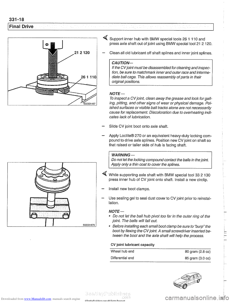
4 Support inner hub with BMW special tools 26 1 110 and
press axle shaft out of joint using BMW special tool 21 2 120.
- Clean all old lubricant off shaft splines and inner joint splines.
If the CVjoint must be disassembled for cleaning and inspec-
tion, be sure to matchmark inner and outer race and interme-
diate ball cage. This allows reassembly
ofparfs in their
original positions.
NOTE-
To inspect a CVjoint, clean away the grease and loolc forgall-
ing, pitting, and other signs of wear orphysical damage. Pol-
ishedsurfaces or visible ball traclts alone are not necessarily
cause forreplacement. Discoloration due to overheating indi-
cates
laclt of lubrication.
- Slide CV joint boot onto axle shaft
- Apply LoctiteO270 or an equivalent heavy-duty loclting corn-
pound to drive axle splines. Position new CV joint on shaft so
that raised or taller side of hub is facing shaft.
WARNING-
Do not let the locking compound contact the balls in the joint.
Apply only a thin coat to cover the splines.
While supporting axle shaft with BMW special tool
33 2 130
press inner hub of CV joint onto shaft. Install a new circlip.
- Install new boot clamps.
- Use sealing gel to seal dust cover to CV joint prior to reinstal-
lation.
NOTE-
* Do not let the ball hub pivot too far in the outer ring of the
joint.
Tlie balls will fa1 out.
Before installing each small boot clamp be sure to
'burp"the
boot by flexing the CVjoint. A small screwdriver inserted be-
tween the boot and the axle shafl will help the process.
CV joint lubricant capacity
Wheel hub end
80 gram (2.8 oz)
Differential end
85 gram (3.0 oz)
Page 763 of 1002
Downloaded from www.Manualslib.com manuals search engine
General ........................... .34 0.2
Special Tools
....................... .34 0.2
E39 brake system
.................... .34 0.4
Electronic braking and stability control
.... .34 0.4
Troubleshooting
..................... .34 0.5
Warnings and cautions
................ .34 0.7
Bleeding Brakes ................... .34 0.8
Brakes, bleeding
..................... .34 0.9
Brake Pads, Calipers and Rotors ... .34 0.1 1
Braking system components .......... .34 0.11
Brake pads,
checking and replacing ..... .34 0.12
Brake rotors, removing and installing
.... .34 0.15
Master Cylinder .................. .34 0.16
Master cylinder, removing and installing
. .34 0.17
Brake Booster .................... .349 0.1
Brake booster check valve
............ .34 0.19
Brake booster, removing and installing
.. .34 0.20
Parking Brake .................... .34 0.22
Parking brake components
............ .34 0.22
Parking
brake, adjusting .............. .34 0.22
Parking bralte shoes, removing
and installing
....................... .34 0.23
Parking
brake cable, replacing ......... .34 0.24
ABS Component Replacement ..... 340-26
Wheel speed sensor. replacing
......... 340-26
ABS impulse wheel
.................. 340-27
DSC lateral acceleration or
rotational rate (yaw) sensor. replacing
... 340-27
DSC steering angle sensor.
removing and installing
............... 340-28
DSC precharge pump.
removing and installing (1998 models)
... 340-29
DSC pressure sensor
(1 999 - 2002 models) ................ 340-30
ABS /traction electronic control
module
(1 997 -1 998 models) .......... 340-31
ABS
/ DSC control module
(1 999
- 2002 models) ................ 340-31
ABS
/ traction control hydraulic unit.
removing and installing
............... 340-31
Page 766 of 1002
Downloaded from www.Manualslib.com manuals search engine
E39 brake system
BMW E39 models are equipped with vacuum power-assisted
four-wheel disc brakes with an integral
Antilock Brake System
(ABS). Single-piston calipers act on vented front and rear ro-
tors. A brake pad wear sensor for each axle indicates when
brake pads need replacement. The dual drum-type parking
brake system is integrated with the rear brake rotors.
Electronic braking and stability control
E39 models were introduced with Automatic Stability Control,
a computer controlled traction control system that uses the
AB5 system in conjunction with engine management controls
to control wheel spin during take-off and maintain vehicle sta-
bility while braking.
Added in the
1998 model year was Dynamic Stability Control
(DSC). This system implements wheel speed modulation
throughout all stages of driving. For example, DSC is able to
reduce understeer by applying differing amounts of braking
force to each wheel, or it can override the engine manage-
ment system during hard cornering.
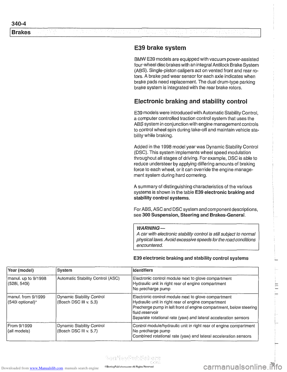
A summary of distinguishing characteristics of the various
systems is shown in the table
E39 electronic braking and
stability control systems.
For ABS, ASC and DSC system and component descriptions,
see
300 Suspension, Steering and Brakes-General.
WARNING-
A car with electronic stability control is still subject to normal
physical laws. Avoid excessive speeds for the road conditions
encountered.
E39 electronic braking and stability control systems
Year (model)
manuf. up to 911998
(528i, 540i)
manuf. from 911999
(540i optional)*
From
911 999
(ail models) System
Automatic Stability Control (ASC) Identifiers
Electronic control module next to glove compartment
Hydraulic unit in right rear of engine compartment
No precharge pump
Dynamic Stability Control
(Bosch DSC
Ill v. 5.3)
Dynamic
Stabil~ty Control
(Bosch DSC
Ill v. 5.7) Electronic
control module next to glove compartment
Hydraulic unit in right rear of engine compartment
Precharge pump in left front of engine compartment, below steering
fluid reservoir
Separate rotational rate (yaw) and lateral acceleration sensors
Control
modulelhydraulic unit in right rear of engine compartment
No precharge pump
Combined rotational rate (yaw) and lateral acceleration sensors
Page 767 of 1002
Downloaded from www.Manualslib.com manuals search engine
Brakes
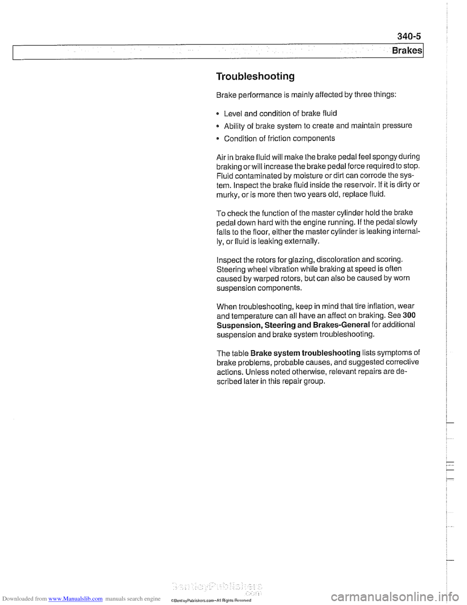
Troubleshooting
Brake performance is mainly affected by three things:
Q Level and condition of brake fluid
Ability of bralte system to create and maintain pressure
Condition of friction components
Air in bralte fluid will
make the brake pedal feel spongy during
braking
orwill increase the bralte pedal force required to stop.
Fluid contaminated by moisture or dirt can corrode the sys-
tem. lnspect the brake fluid inside the reservoir. If it is dirty or
murky, or is more then two years old, replace fluid.
To
check the function of the master cylinder hold the bralte
pedal down hard with the engine running. If the pedal slowly
falls to the floor, either the master cylinder is leaking internal-
ly, or fluid is leaking externally.
lnspect the rotors for glazing, discoloration and scoring.
Steering wheel vibration while braking at speed is often
caused by warped rotors, but can also be caused by worn
suspension components.
When troubleshooting, keep in mind that tire inflation, wear
and temperature can all have an affect on braking. See
300
Suspension, Steering and Brakes-General for additional
suspension and brake system troubleshooting.
The table Brake system troubleshooting lists symptoms of
brake problems, probable causes, and suggested corrective
actions. Unless noted otherwise, relevant repairs are de-
scribed later in this repair group.