BODY BMW 528i 1998 E39 Repair Manual
[x] Cancel search | Manufacturer: BMW, Model Year: 1998, Model line: 528i, Model: BMW 528i 1998 E39Pages: 1002
Page 724 of 1002
Downloaded from www.Manualslib.com manuals search engine
330-28
Rear Suspension
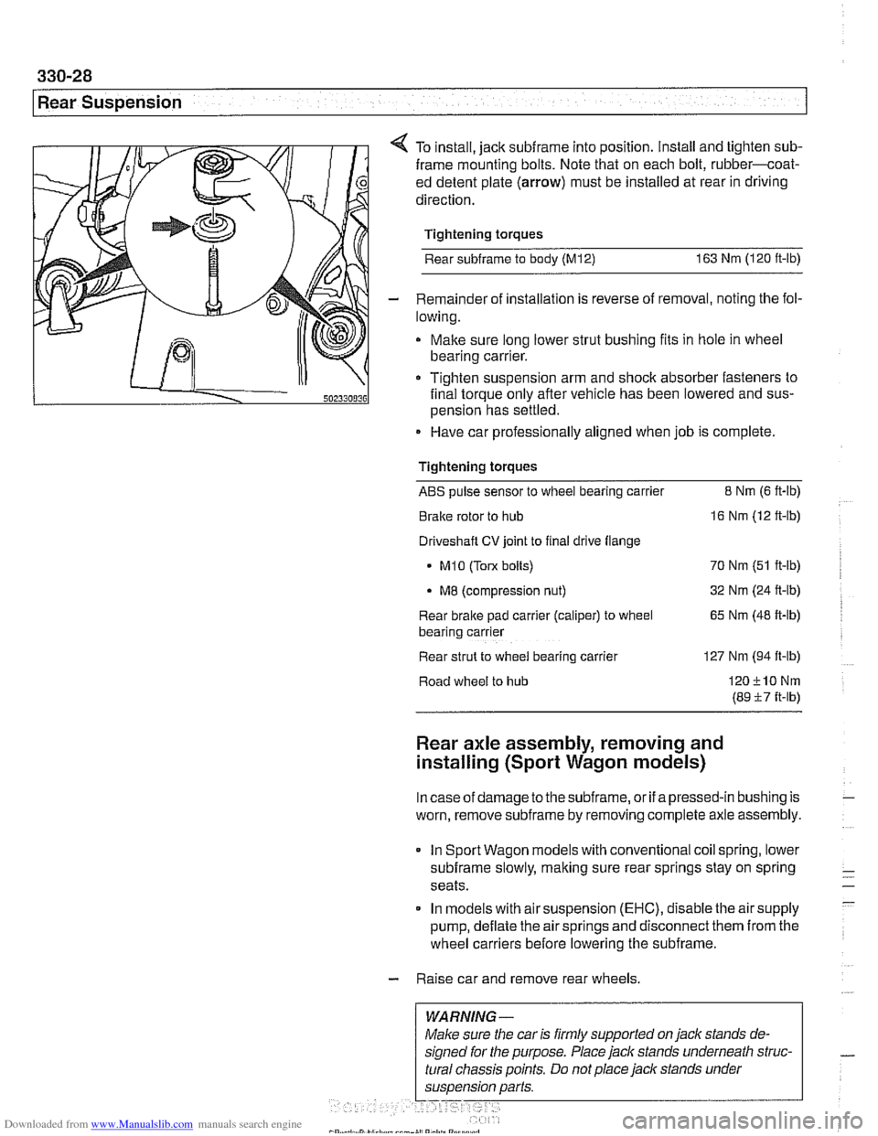
4 To install, jack subframe into position. Install and tighten sub-
frame mounting bolts. Note that on each bolt, rubber-coat-
ed detent plate
(arrow) must be installed at rear in driving
direction.
Tightening torques
Rear
subframe to body (M12) 163 Nm (120 ft-lb)
- Remainder of installation is reverse of removal, noting the fol-
lowing.
Make sure long lower strut bushing fits in hole in wheel
bearing carrier.
111 0 Tighten suspension arm and shoclc absorber fasteners to
502330036 final torque only afler vehicle has been lowered and sus-
pension has settled.
Have car professionally aligned when job is complete
Tightening torques
ABS pulse sensor to wheel bearing carrier 8 Nrn (6 ft-lb)
Brake rotor to hub
16 Nm (12 ft-lb)
Driveshaft
CV joint to final drive flange
- MI0 (Tow bolts) 70 Nm (51 ft-lb)
MB (compression nut) 32
Nm (24 ft-lb)
Rear brake pad
carrler (caliper) to wheel 65 Nm (48 ft-lb)
bear~ng carrler
Rear strut to
wheel bearlng carrler 127 Nm (94 ft-lb)
Road wheel to hub
120210Nrn
(89 57 ft-lb)
Rear axle assembly, removing and
installing (Sport Wagon models)
Incaseof damage to thesubframe, or if apressed-in bushing is
worn, remove
subframe by removing complete axle assembly.
In Sport Wagon models with conventional coil spring, lower
subframe slowly, making sure rear springs stay on spring
seats.
In models with air suspension
(EHC), disable the air supply
pump, deflate the air springs and disconnect them from the
wheel carriers before lowering the subframe.
- Raise car and remove rear wheels.
WARNING-
Page 726 of 1002
Downloaded from www.Manualslib.com manuals search engine
330-30
I Rear Suspension
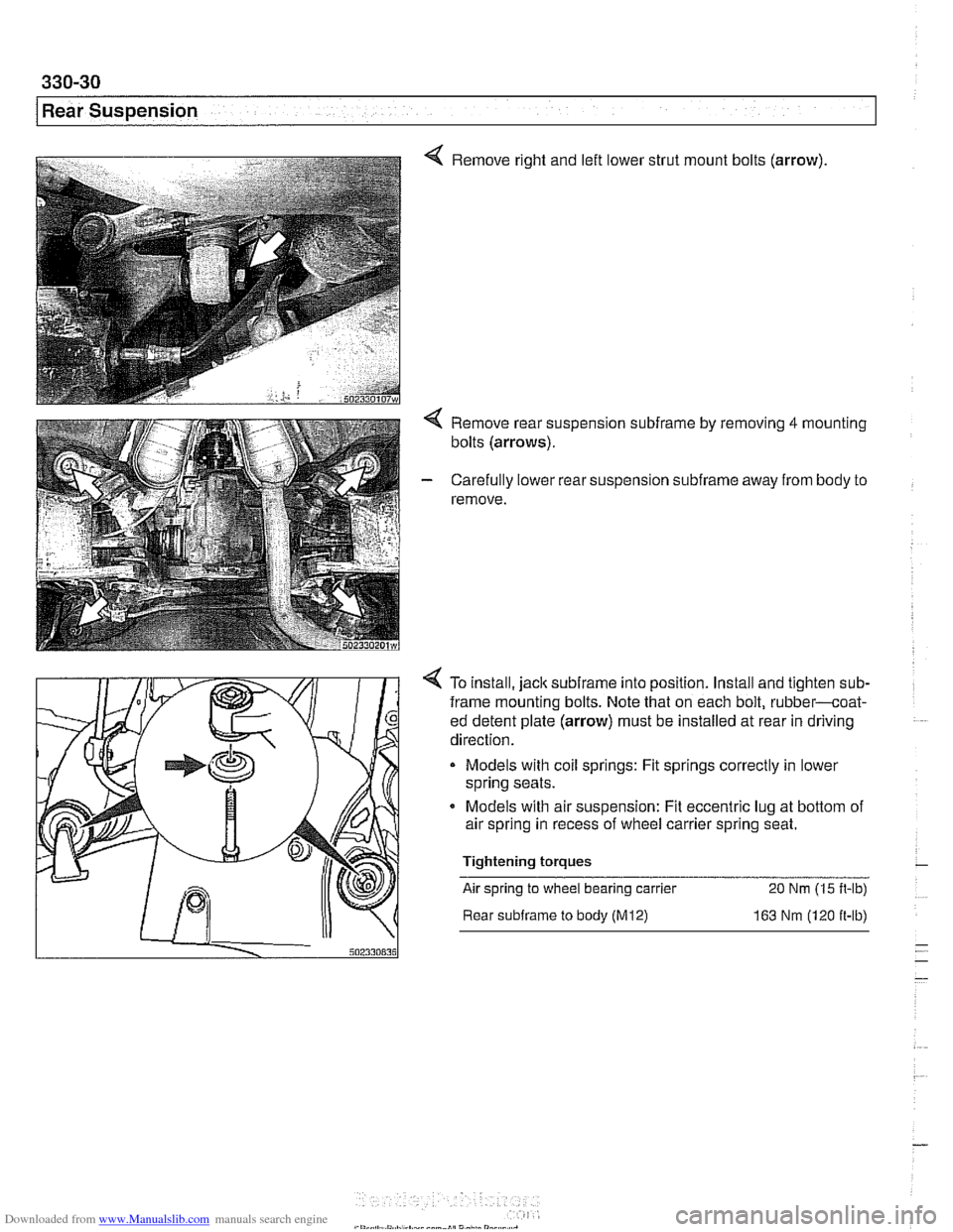
Remove right and left lower strut mount bolts (arrow).
Remove rear suspension subframe by removing 4 mounting
bolts
(arrows).
Carefully lower rear suspension subframe away from body to
remove.
To install, jack
subframe into position. Install and t~ghten sub-
frame mounting bolts. Note that on each bolt, rubber-coat-
ed detent plate
(arrow) must be installed at rear in driving
direction.
Models
w~th coil springs: Fit springs correctly in lower
spring seats.
Models with air suspension: Fit eccentric lug at bottom of
air
sprlng in recess of wheel carrier spring seat.
Tightening torques
-
Air spring to wheel bearing carrier 20 Nm (1 5 ft-lb)
Rear subframe to body (M12) 163 Nm (120 ft-lb)
-
Page 749 of 1002
Downloaded from www.Manualslib.com manuals search engine
Final Drive
Final drive, removing and installing
- Raise rear of car.
WARNING-
Make sure that the car is firmly supported on jack stands de-
signed for the purpose. Place the jaclc stands beneath struc-
tural chassis
~oints. Do not i lace iaclc stands under
( suspension barfs.
Remove exhaust system. See 180 Exhaust System.
Disconnect drive shaft from final drive. See
260 Driveshaft.
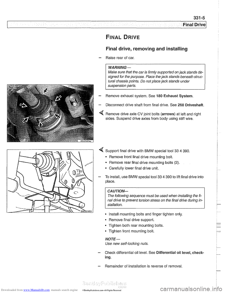
Remove drive axle CV joint bolts (arrows) at left and right
sides. Suspend drive axles from body using stiff wire.
4 Support final drive with BMW special tool 33 4 390.
* Remove front final drive mounting bolt.
Remove rear final drive mounting bolts
(2).
Carefully lower final drive unit.
- To install, use BMW special tool 33 4 390 to lift final drive into
place.
CA UTIOP&
The following sequence must be used when installing the fi-
nal drive to prevent torsion stress on the final drive during in-
Install mounting bolts and finger tighten only.
Remove final drive support.
Tighten both rear mounting bolts.
Tighten front mounting bolt.
NOTE-
Use new self-locking nuts.
- Check differential oil level. See Differential oil level, check-
ing.
- Remainder of installation is reverse of removal.
Page 754 of 1002
Downloaded from www.Manualslib.com manuals search engine
. .
Final Drive Final drive output shaft seals, replacing
- Remove exhaust system (if necessary). See 180 Exhaust
System.
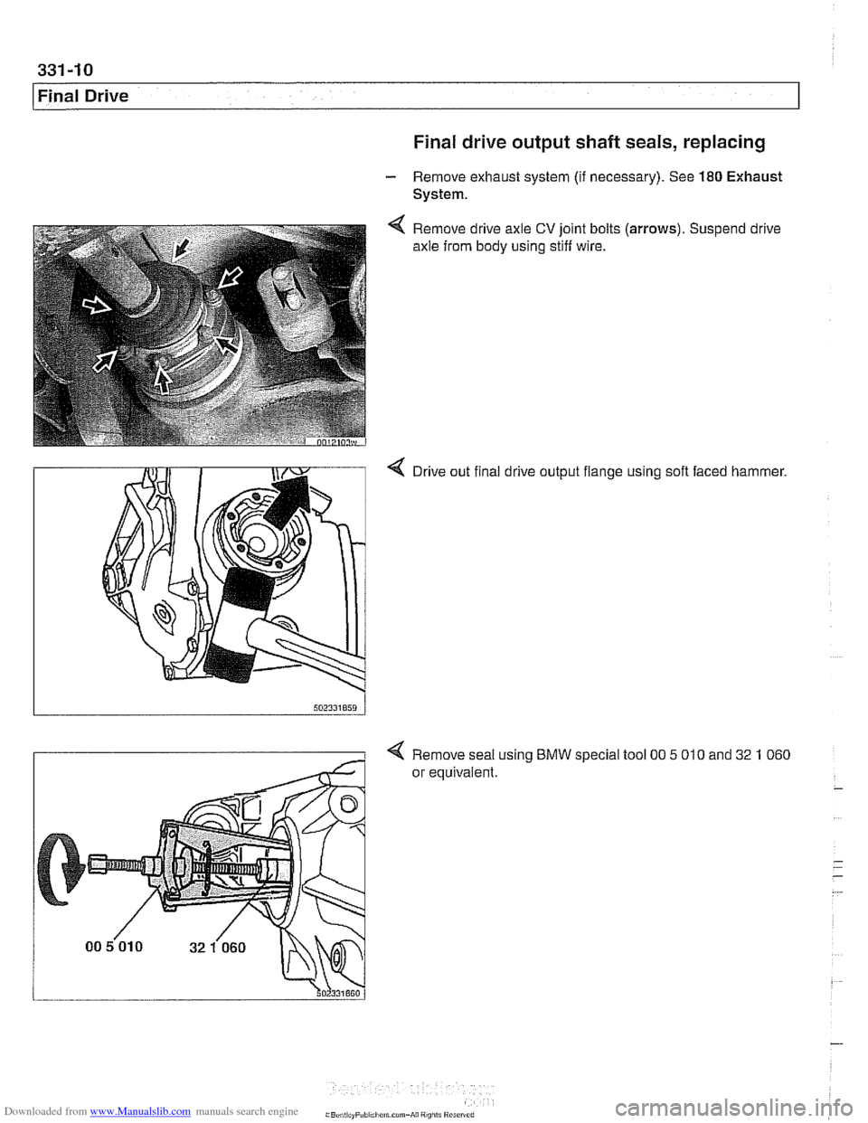
Remove drive axle
CV joint bolts
axle from body using stiff wire. (arrows).
Suspend drive
4 Drive out final drive output flange using soft faced hammer.
4 Remove seal using BMW special tool 00 5 010 and 32 1 060
or equivalent.
Page 771 of 1002
Downloaded from www.Manualslib.com manuals search engine
Brakes
Brakes, bleeding
The procedure below requires a BMW Service Tester (DIS-
pluslGTl/MoDiC).
- Determine type of traction control (ASC, DSC with precharge
pump, DSC without precharge pump). Be sure to use correct
specification brake fluid, according to application table below.
Brake fluid applications
ABS I ASC and ABS / DSC models DOT 4 brake fluid
with precharge pump (to 911998)
ABS I DSC models without precharge DOT 4 low viscosity
pump (911998 and later) brake
fluid
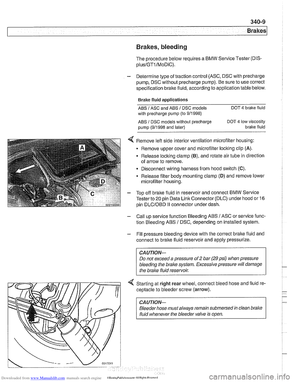
< Remove left side interior ventilation microfilter housing:
Remove upper cover and microfilter loclting clip
(A).
Release locking clamp (B), and rotate air tube in direction
of arrow to remove.
Disconnect wiring harness from hood switch
(C).
Release filter body mounting clamp (D) and remove lower
microfilter housing.
- Top off bralte fluid in reservoir and connect BMW Service
Tester to
20 pin Data Link Connector (DLC) under hood or 16
pin
DLCIOBD I1 connector under dash.
- Call up service function Bleeding ABS / ASC or service func-
tion Bleeding ABS
/ DSC, depending on installed system.
- Fill pressure bleeding device with the correct brake fluid and
connect to brake fluid reservoir and apply pressurize.
Do not exceed a pressure of
2 bar (29 psi) when pressure
bleeding the
brake system. Excessive pressure will damage
4 Starting at right rear wheel, connect bleed hose and fluid re-
ceptacle to bleeder screw (arrow).
CA UTlON-
Bleeder hose must always remain submersed in clean brake
fluid whenever the bleeder valve is open.
Page 774 of 1002
Downloaded from www.Manualslib.com manuals search engine
340-1 2
Brakes Brake pads, checking and replacing
Brake pads can be replaced without disconnecting the brake
fluid hose from the caliper or having to bleed the brakes. The
rotors can be replaced without disassembling wheel hub and
bearing. Always machine or replace rotors in pairs. Replace
pads in sets.
Front and rear brake pad replacement procedures are identical.
WARNING -
* Altllough semi-metallic andmetallic brale friction materials
in brake pads or shoes no longer contain asbestos, they
produce dangerous dust.
Treat all
brale dust as a hazardous material.
Do not create dust by grinding, sanding, or cleaning
brake friction surfaces with compressed air.
CAUTION--
Pressing caliper piston in may cause brake fluid reservoir to
overflow To prevent this, use a clean syringe to first remove
some fluid
from reservoir.
Raise car and remove wheels,
WARNING-
Make sure that the car is firmly supported on jack stands de-
signed for the purpose. Place jack stands beneath structural
chassis points. Do not place jack stands under suspension
parts.
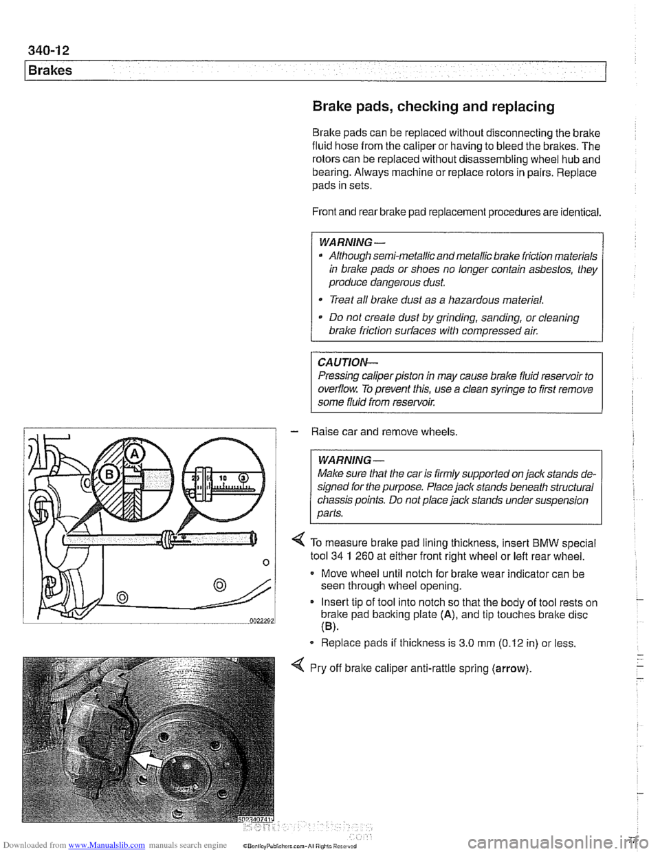
/ 4 To measure brake pad lining thickness, insert BMW special
n 1 tool 34 1 260 at either frontilght wheel or left rear wheel -
Move wheel until notch for brake wear indicator can be
seen through wheel opening.
Insert tip of tool into notch so that the body of tool rests on
brake pad backing plate
(A), and tip touches bralte disc
(B).
Replace pads if thickness is 3.0 mm (0.12 in) or less.
Pry off
bralte calipe~ , anti-rattle spring (arrow).
Page 779 of 1002
Downloaded from www.Manualslib.com manuals search engine
Brakes
Master cylinder, removing and installing
CAUTlOI\C
Brake fluid is highly corrosive and dangerous to the environ-
ment. Dispose of it properly.
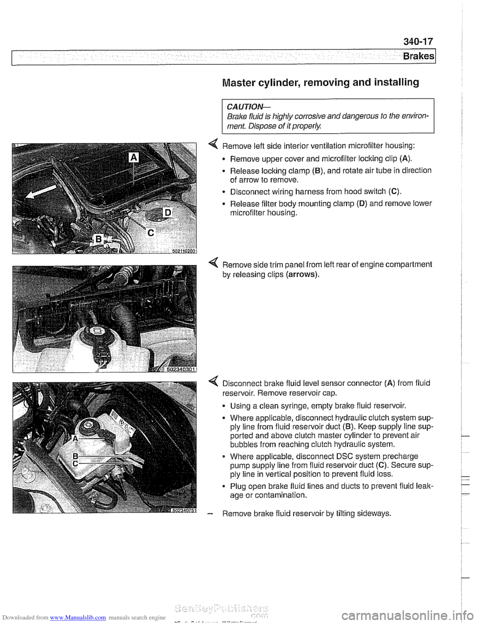
4 Remove left side interior ventilation microfilter housing:
Remove upper cover and microfilter locking clip
(A).
- Release locking clamp (B), and rotate air tube in direction
of arrow to remove.
Disconnect wiring harness from hood switch
(C).
Release filter body mounting clamp (D) and remove lower
microfilter housing.
4 Remove side trim panel from left rear of engine compartment
by releasing clips
(arrows).
4 Disconnect bralte fluid level sensor connector (A) from fluid
reservoir. Remove reservoir cap.
. Using a clean syringe, empty bralte fluid reservoir.
Where applicable, disconnect hydraulic clutch system sup-
ply line from fluid reservoir duct
(5). Keep supply line sup-
ported and above clutch master cylinder to prevent air
bubbles from reaching clutch hydraulic system.
Where applicable, disconnect DSC system precharge
pump supply line from fluid reservoir duct
(C). Secure sup-
ply line in vertical position to prevent fluid loss.
Plug open brake fluid lines and ducts to prevent fluid leak-
age or contamination.
- Remove brake fluid reservoir by tilting sideways.
Page 787 of 1002
Downloaded from www.Manualslib.com manuals search engine
340-25
Brakes
- Remove complete exhaust system as described in 180 Ex-
haust System.
- Remove center tunnel heat shield.
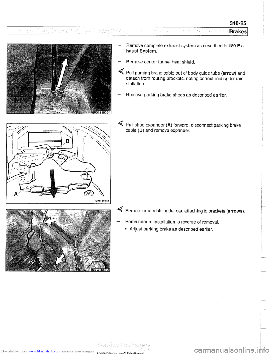
< Pull parlting brake cable out of body guide tube (arrow) and
detach from routing bracltets, noting correct routing for rein-
stallation.
- Remove parlting bralte shoes as described earlier.
4 Pull shoe expander (A) forward, disconnect parlting bralte
cable
(B) and remove expander.
4 Reroute new cable under car, attaching to bracltets (arrows).
- Remainder of installation is reverse of removal.
Adjust parking brake as described earlier.
Page 790 of 1002
Downloaded from www.Manualslib.com manuals search engine
340-28
Brakes
- Remove sensor mounting screws. Lift sensor away from
bracket.
- Installation is reverse of removal.
CAUTION-
Be sure to tighten the DSC acceleration sensor(s) and
mounting bracket, if applicable, to specified torques. The
sensor
is vibration sensitive and subject to cause DSC
malfunctions if installed improperly.
a After replacing the sensor, perform sensor adjustment
using either DIS or
MoDiC under Service Functions
menu.
Tightening
torques
Lateral acceleration I rotational rate sensor 8 Nm (6 R-ib)
to bracket
Sensor bracket to body
8 Nm (6 ft-lb)
DSC steering angle sensor, removing and
installing
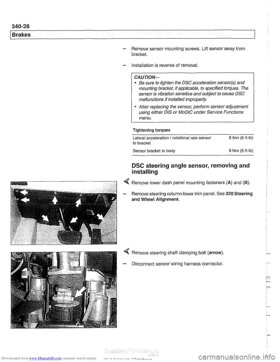
4 Remove lower dash panel mounting fasteners (A) and (5).
- Remove steering column lower trim panel. See 320 Steering
and Wheel Alignment.
Remove steering shaft clamping bolt (arrow).
Disconnect sensor wiring harness connector.
Page 794 of 1002
Downloaded from www.Manualslib.com manuals search engine
340-32
Brakes
The procedure for removing the ABS I ASC or ABS I DSC hy-
draulic unit is similar for all models. The unit is located at the
right rear of the engine compartment.
- Using a clean syringe, empty brake fluid reservoir.
CAUTION-
Brake fluid is highly corrosive and dangerous to the environ-
ment. Dispose of it
properiw
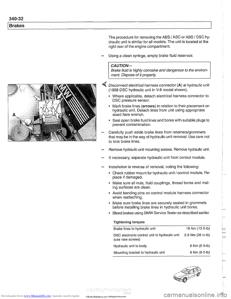
4 Disconnect electrical harness connector (A) at hydraulic unit
(1998 DSC hydraulic unit in V-8 model shown).
Where applicable, detach electrical harness connector to
DSC pressure sensor.
Mark brake lines
(arrows) in relation to their placement on
hydraulic unit. Detach lines from unit using appropriate
sized flare wrench.
Seal open brake fluid lines and bores with suitable plugs to
prevent contamination.
- Carefully push aside brake lines from retainerslgrommets
that may be in the way of hydraulic unit removal. Use care not
to
kink brake lines.
- Remove hydraulic unit mounting screws. Remove hydraulic unit.
- If necessary, separate hydraulic unit from control module.
- Installation is reverse of removal, noting the following:
Check rubber mount for hydraulic unit/control module. Re-
place if damaged.
Make sure all nuts, fluid couplings, thread bores and mat-
ing surfaces are clean.
Avoid bending pins on control module harness connector
when reattaching.
Make sure brake lines are securely seated in grommets
before installing brake lines in hydraulic unit bores.
Bleed brakes using
BMW Service Testeras described earlier.
Tightening torques Brake lines to hydraulic unit
18 Nm (13 ft-lb)
DSC electronic control unit to hydraulic unit 2.9 Nrn (26 in-lb)
(use new screws)
Hydraulic unit to body
8 Nm (6 ft-ib)
Mounting bracket to hydraulic unit 8 Nrn (6 ft-lb)