ele BMW 528i 1998 E39 Manual PDF
[x] Cancel search | Manufacturer: BMW, Model Year: 1998, Model line: 528i, Model: BMW 528i 1998 E39Pages: 1002
Page 150 of 1002
Downloaded from www.Manualslib.com manuals search engine
11 3-56
I Cvlinder Head Removal and Installation
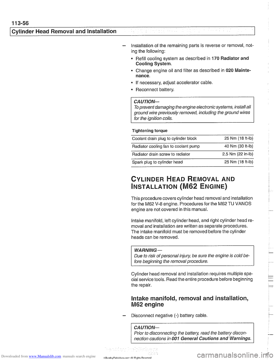
- Installation of the remaining parts is reverse or removal, not-
ing the following:
- Refill cooling system as described in 170 Radiator and
Cooling System.
Change engine oil and filter as described in
020 Mainte-
nance.
If necessary, adjust accelerator cable.
a Reconnect battery.
CAUTION- To prevent damaging the engine electronic systems, installall
ground wire previously removed, including the ground wires
for the
ionition coils.
Tightening torque Coolant drain
pluq to cylinder bloclc 25 Nm (1 8 ft-lb)
Radiator cooling fan to coolant pump 40 Nm (30 ft-lb) -
Radiator drain screw to radiator 2.5
Nm (22 in-lb)
spark plug to cylinder head 25
Nm (1 8 ft-lb)
CYLINDER MEAD REMOVAL AND
INSTALLATION (M62 ENGINE)
This procedure covers cylinder head removal and installation
for the
M62 V-8 engine. Procedures forthe M62 TU VANOS
engine are not covered in this manual.
Intake manifold, left cylinder head, and right cylinder head re-
moval and installation are written as separate procedures.
The intake manifold must be removed before the cylinder
heads can be removed.
WARNING
-
Due to risk of personal injuv be sure the engine is cold be-
fore beginning the removal procedure.
Cylinder head removal and installation requires multiple spe-
cial service tools. Read the entire procedure before beginning
the repair.
Intake manifold, removal and installation,
M62 engine
- Disconnect negative (-) battery cable.
CAUTION- Prior to disconnecting the
batterj read the baitery discon-
nection cautions
in 001 General Cautions and Warnings.
Page 151 of 1002
Downloaded from www.Manualslib.com manuals search engine
Cylinder Head Removal and Installation /
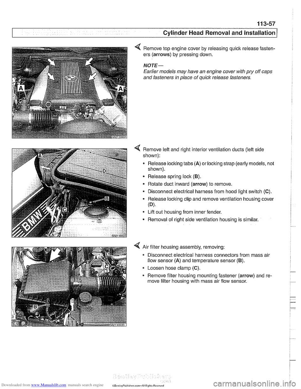
4 Remove top engine cover by releasing quick release fasten-
ers (arrows) by pressing down.
NOTE-
Earlier models may have an engine cover with pry off caps
and fasteners
In place of quick release fasteners.
4 Remove left and right interior ventilation ducts (left side
shown):
- Release locking tabs (A) or locking strap (early models, not
shown).
Release spring lock (B).
* Rotate duct inward (arrow) to remove.
Disconnect electrical harness from hood light switch (C).
Release locking clip and remove ventilation housing cover
(D).
Lift out housing from inner fender.
- Removal of right side ventilation housing is similar.
4 Air filter housing assembly, removing:
Disconnect electrical harness connectors from mass air
flow sensor (A) and temperature sensor (B).
Loosen hose clamp (C).
Remove filter housing mounting fastener (arrow) and re-
move filter housing with mass air flow sensor.
Page 153 of 1002
Downloaded from www.Manualslib.com manuals search engine
- .-
.. Cylinder Head Removal and Installation I -
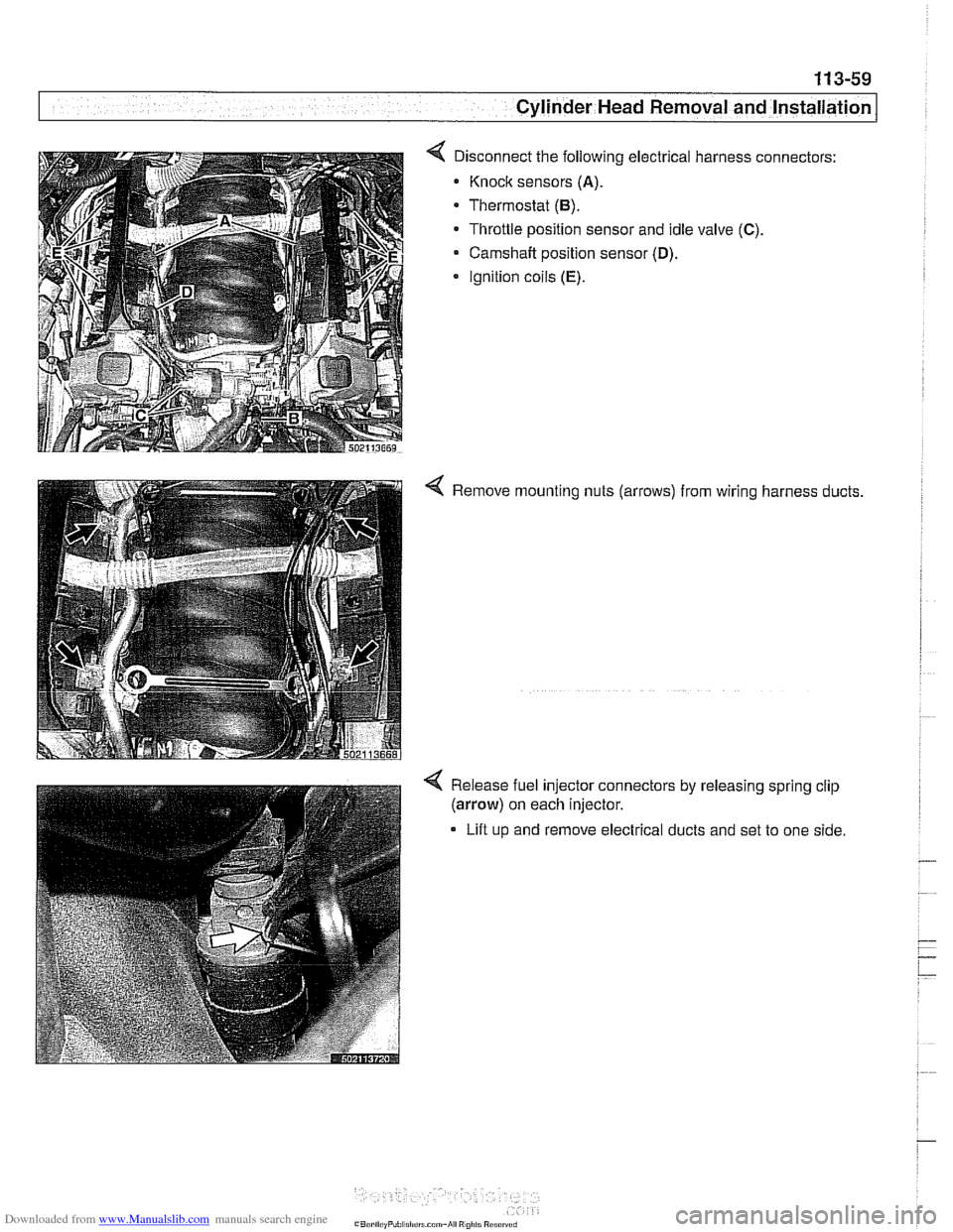
< Disconnect the following electrical harness connectors:
Knock sensors
(A).
Thermostat (6).
Throttle position sensor and idle valve (C).
Camshaft position sensor (D).
Ignition coils (E).
< Remove mounting nuts (arrows) from wiring harness ducts.
4 Release fuel injector connectors by releasing spring clip
(arrow) on each injector.
Lift up and remove electrical ducts and set to one side
Page 154 of 1002
Downloaded from www.Manualslib.com manuals search engine
1 13-60
Cylinder Head Removal and Installation
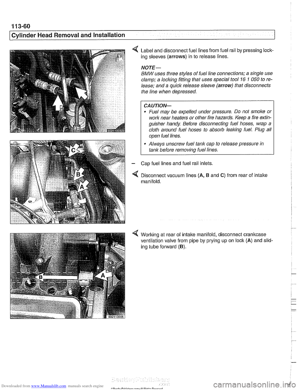
Label and disconnect fuel lines from fuel rail by pressing lock-
ing sleeves
(arrows) in to release lines.
NOTE-
BMW uses three styles of fuel line connections; a single use
clamp; a locking fitting that uses special tool
16 1 050 to re-
lease; and a quick release sleeve
(arrow) that disconnects
the line when depressed.
CAUTION-
Fuel may be expelled under pressure. Do not smoke or
work near heaters or other fire hazards. Keep a fire
exfin-
guisher handy Before disconnecting fuel hoses, wrap a
cloth around fuel hoses to absorb
leaking fuel. Plug all
I ooen fuel lines. I
Always unscrew fuel tank cap to release pressure in
tank before
removinq fuel lines.
Cap fuel lines and fuel rail inlets.
Disconnect vacuum lines
(A, B and C) from rear of intake
manifold.
Working at rear of intake manifold, disconnect crankcase
ventilation valve from pipe by prying up on lock
(A) and slid-
ing tube forward
(B).
Page 166 of 1002
Downloaded from www.Manualslib.com manuals search engine
/Cylinder Head Removal and Installation
- Remainder of installation is reverse of removal, noting the fol-
lowing:
Use new gaskets when mounting intake
manifold. Tighten
nuts finger tight first, then torque to specification in stages
working diagonally from center out.
Be sure to reinstall ignition coil ground straps at cylinders
no.
3 and no. 7. See 120 Ignition System.
Reinstall cooling fan and shroud. See
170 Radiator and
Cooling System.
Refill and bleed cooling system as described in
170 Radi-
ator and Cooling System.
Change engine oil and filter as described in
020 Mainte-
nance.
CA UTIOG
To prevent damaging engine electricalsystems, be sure to in-
stall all ground wires previously removed.
Tightening torques
Camshaft sprocket to camshaft 15
Nm (11 H-lb)
Coolant manifold to cylinder head 10 Nm (7.5 H-lb)
Cylinder head cover nuts 10 Nm (7.5 ft-lb)
Exhaust manifold to head 22 Nm (17 ft-lb)
Engine mounts to subirame 42 Nm (30 ft-lb)
Spark plugs to cylinder head 22 Nm (17 ft-lb)
Right cylinder head, removing, M62 engine
- Remove left side exhaust manifold. See 180 Exhaust Sys-
tem.
- Remove intake manifold. See Intake manifold, removal
and installation,
M62 engine.
- Drain engine coolant. See 170 Radiator and Cooling Sys-
tem.
WARNING-
Use extreme caution when draining and disposing of engine
coolant.
Coolanl is poisonous andlellial lo liumans andpels.
Pets are
altracled to coolant because of 11s sfieet smell and
fasle. Seelc medcal anenfion immed~alely if coolant is ingesl-
. .-
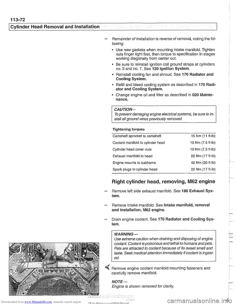
< Remove engine coolant manlold mo~nlng fasreners and
carei~lly remove manifo d.
. I
NOTE
Engine 8s slioivn removed lor clarify
Page 176 of 1002
Downloaded from www.Manualslib.com manuals search engine
1 13-82
1 Cylinder Head Removal and Installation
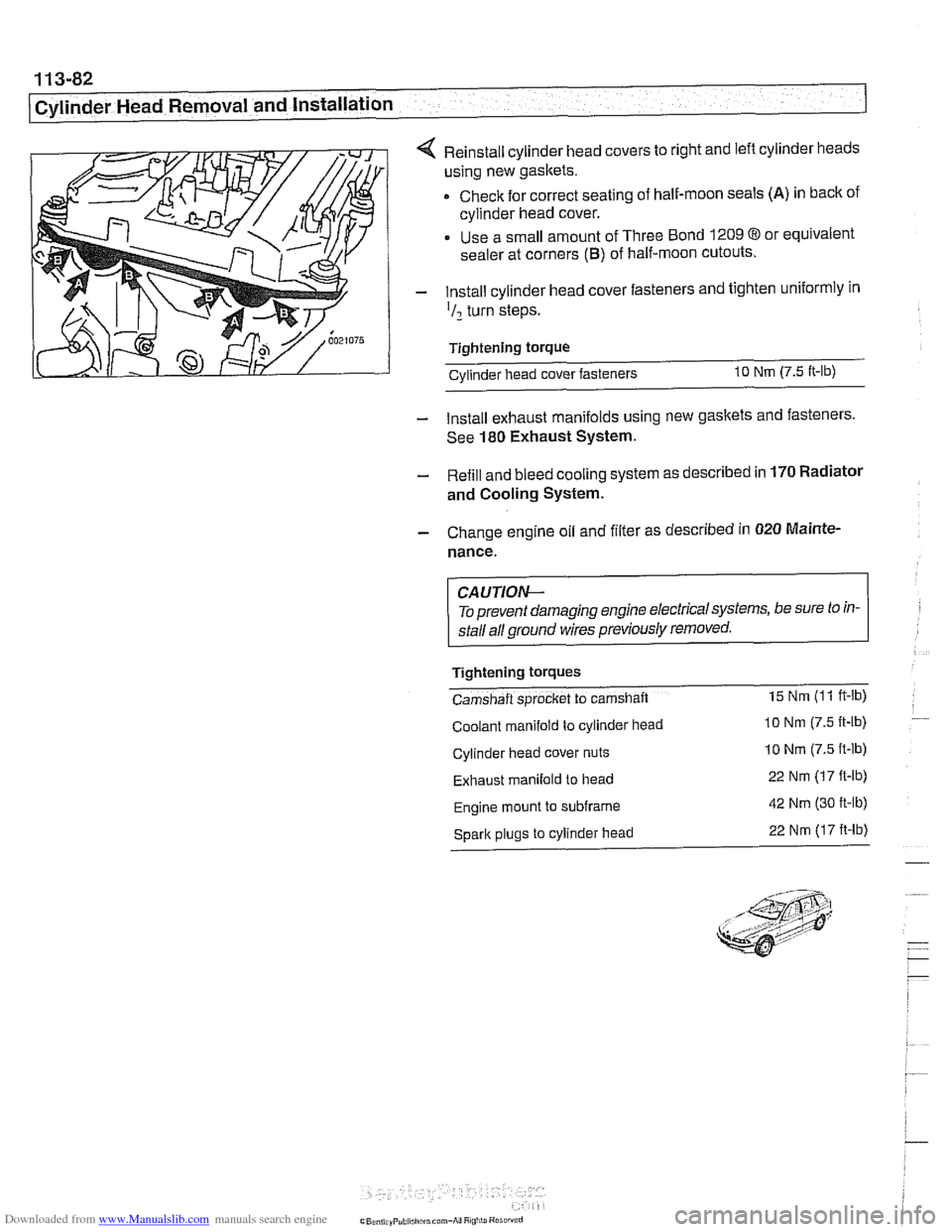
4 Reinstall cylinder head covers to right and left cylinder heads
using new gaskets.
Check for correct seating of half-moon seals
(A) in back of
cylinder head cover.
Use a small amount of Three Bond
1209 8 or equivalent
sealer at corners
(B) of half-moon cutouts.
- Install cylinder head cover fasteners and tighten uniformly in
'I2 turn steps.
Tightening torque Cvlinder head cover fasteners
10 Nm (7.5 It-lb)
- Install exhaust manifolds using new gaskets and fasteners.
See
180 Exhaust System.
- Refill and bleed cooling system as described in 170 Radiator
and Cooling System.
- Change engine oil and filter as described in 020 Mainte.
nance.
CA UTIOW-
To prevent damaging engine electricalsystems, be sure to in-
stall all ground wires previously removed.
Tightening
tOrqUeS
Camshaft sprocket to camshaft 15 Nm (1 1 ft-lb)
Coolant manifold to cylinder head lo Nm (7.5 It-lb)
Cylinder head cover nuts 10 Nm (7.5 ft-lb)
Exhaust manifold to head 22 Nm (17 ft-lb)
Engine mount to subframe 42 Nm (30 ft-lb)
Spark plugs to cylinder head 22 Nm (17 ft-lb)
Page 183 of 1002
Downloaded from www.Manualslib.com manuals search engine
Cylinder Head and valvetrain1
Hydraulic lifters, checking and replacing
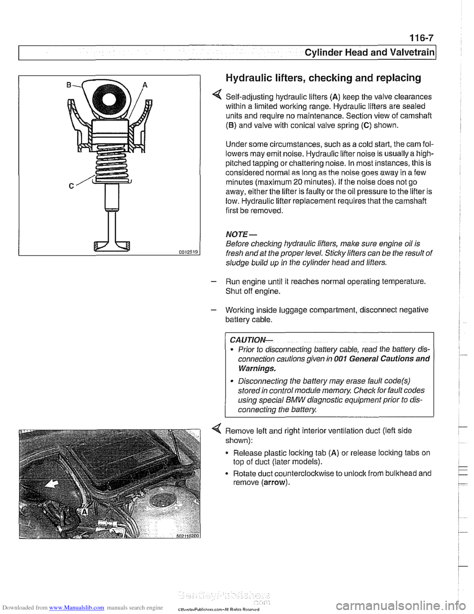
Self-adjusting hydraulic lifters (A) keep the valve clearances
within a limited working range. Hydraulic lifters are sealed
units and require no maintenance. Section view of camshaft
(6) and valve with conical valve spring (C) shown.
Under some circumstances, such as a cold start, the cam fol-
lowers may emit noise. Hydraulic lifter noise is usually a
high-
pitched tapping or chattering noise. In most instances, this is
considered normal as long as the noise goes away in a few
minutes (maximum
20 minutes). If the noise does not go
away, either the lifter is faulty or the oil pressure to the lifter is
low. Hydraulic lifter replacement requires that the camshaft
first be removed.
NOTE-
Before checking hydraulic lifters, male sure engine oil is
fresh and at the proper level.
Sticky lifters can be the result of
sludge build up in the cylinder head and lifters.
- Run engine until it reaches normal operating temperature.
Shut off engine.
- Working inside luggage compartment, disconnect negative
battery cable.
CAUTION-
Prior to disconnecting battery cable, read the baltery dls-
connection cautions given In 001 General Cautions and
Warnings.
Disconnecting the battery may erase fault
code(s)
stored in control module memory Check for fault codes
4 Remove left and right interior ventilation duct (left side
shown):
Release plastic locking tab
(A) or release loclting tabs on
top of duct (later models).
Rotate duct counterclockwise to
unloclt from bulithead and
remove (arrow).
Page 184 of 1002
Downloaded from www.Manualslib.com manuals search engine
Cylinder Head and Valvetrain
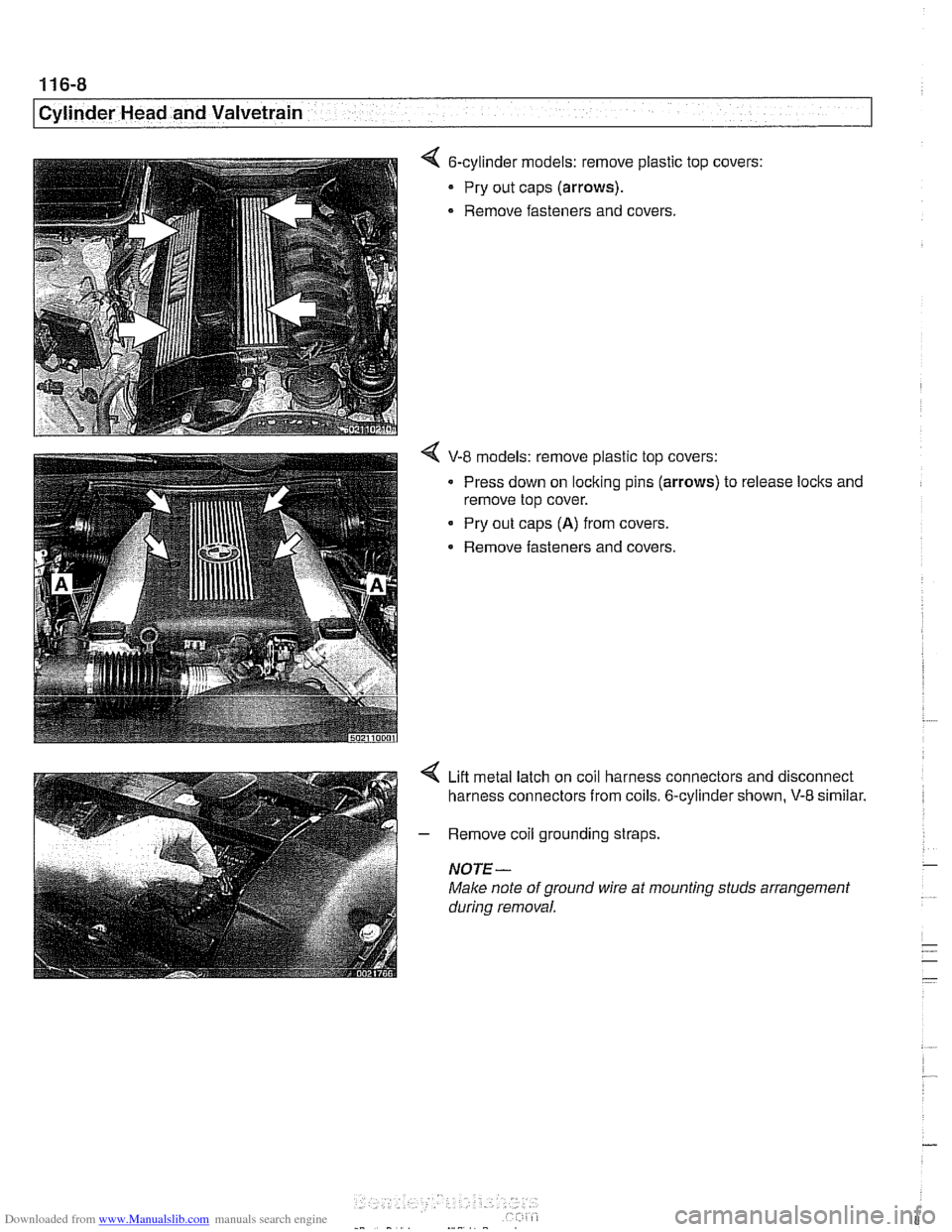
&cylinder models: remove plastic top
- Pry out caps (arrows).
- Remove fasteners and covers. covers:
4 V-8 models: remove plastic top
covers:
Press down on locking pins
(arrows) to release locks and
remove top cover.
Pry out caps
(A) from covers.
Remove fasteners and covers.
4 Lift metal latch on coil harness connectors and disconnect
harness connectors from coils. 6-cylinder shown,
V-8 similar.
- Remove coil grounding straps.
NOTE-
Make note of ground wire at mounting studs arrangement
during removal.
- -- -
-
Page 185 of 1002
Downloaded from www.Manualslib.com manuals search engine
11 6-9
Cvlinder Head and valvetrain1
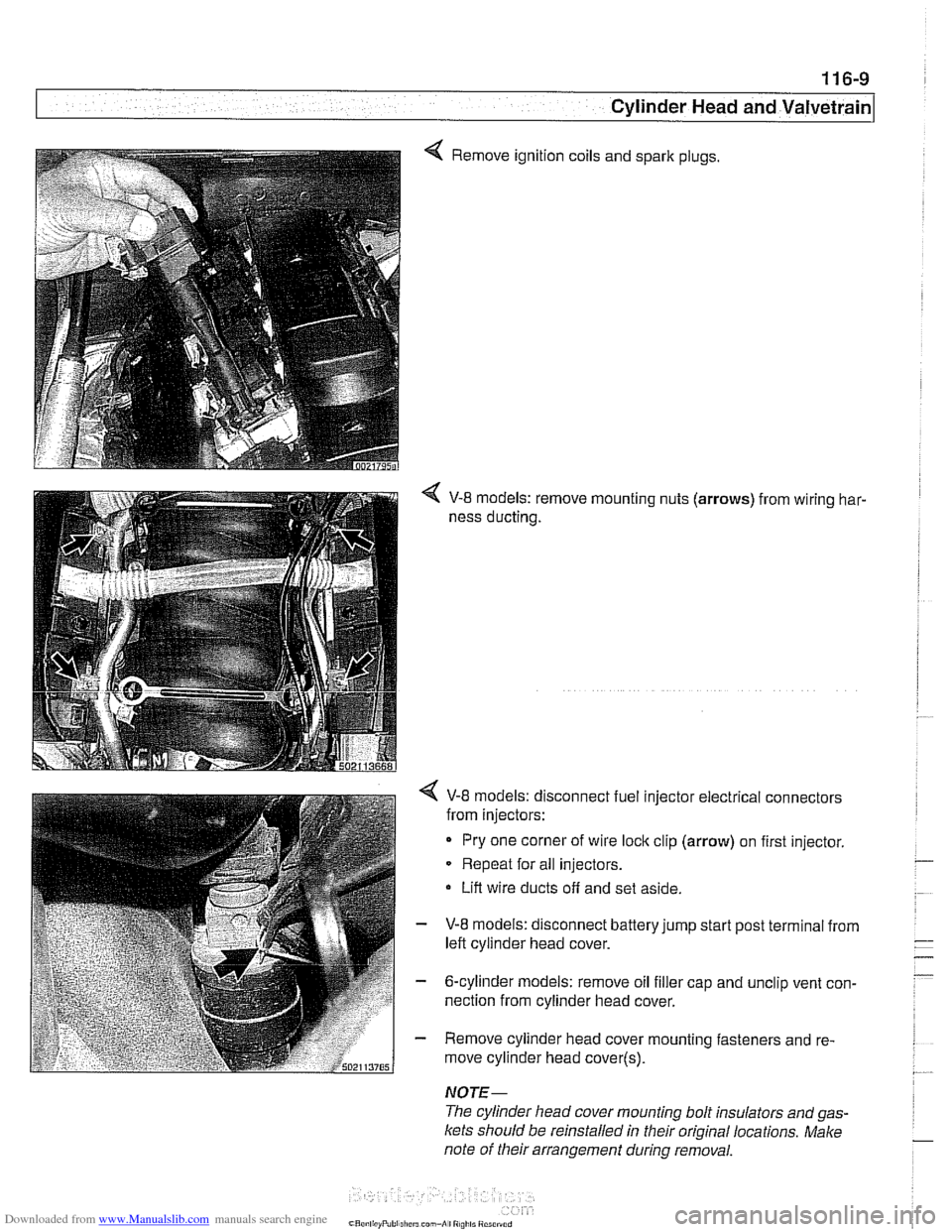
4 Remove ignition coils and spark plugs.
V-8 models: remove mounting nuts (arrows) from wiring har-
ness ducting.
< V-8 models: disconnect fuel injector electrical connectors
from injectors:
Pry one corner of wire
loclc clip (arrow) on first injector.
Repeat for all injectors.
Lift wire ducts off and set aside.
- V-8 models: disconnect battery jump start post terminal from
left cylinder head cover.
- 6-cylinder models: remove oil filler cap and unclip vent con-
nection from cylinder head cover.
- Remove cylinder head cover mounting fasteners and re-
move cylinder head cover(~).
NOTE-
The cylinder head cover mounting bolt insulators and gas-
Icets should be reinstalled in their original locations. Make
note of their arrangement
during removal.
Page 192 of 1002
Downloaded from www.Manualslib.com manuals search engine
.
Cylinder Head and Valvetrain
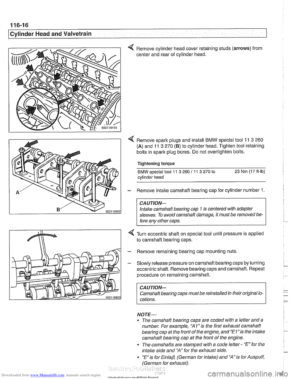
< Remove cylinder head cover retaining studs (arrows) from
center and rear of cylinder head.
< Remove spark plugs and install BMW special tool 11 3 260
(A) and 11 3 270 (6) to cylinder head. Tighten tool retaining
bolts in spark plug bores. Do not overtighten bolts.
Tightening
torque
BMW special tool 11 3 260 I1 1 3 270 to 23 Nm (17 It-lb)
cylinder head
- Remove intake camshaft bearing cap for cylinder number 1.
CA UTIOG
Intake camshaft bearing cap 1 is centered with adapter
sleeves. To avoid
can~sllaft daniage, it must be removed bs-
fore any other caps.
Turn eccentric shaft on special tool until pressure is applied
to camshaft bearing caps.
- Remove remaining bearing cap mounting nuts
- Slowly release pressure on camshaft bearing caps by turning
eccentric shaft. Remove bearing caps and camshaft. Repeat
procedure on remaining camshaft.
CAUTION-
Camshaft bearing caps must be reinstalled in their original lo-
cations.
NOTE-
The camshaft bearing caps are coded with a letter anda
number. For example,
'XI" is the first exhaust camshaft
bearing cap at the front of the engine, and
"El "is the intalce
camshaft bearing cap at the front of the engine.
0 The camshafts are stamped with a code letter - "E" for the
intake side and 'MA" for the exhaust side.
0 "E is for Einlap, (German for intake) and 'XA"is for Auspuff,
(German for exhaust).