ele BMW 528i 1998 E39 Workshop Manual
[x] Cancel search | Manufacturer: BMW, Model Year: 1998, Model line: 528i, Model: BMW 528i 1998 E39Pages: 1002
Page 306 of 1002
Downloaded from www.Manualslib.com manuals search engine
I Camshaft Timins Chain
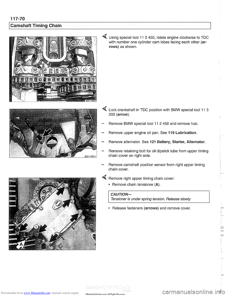
4 Using special tool 11 2 450, rotate engine clocltwise to TDC
with number one cylinder cam lobes facing each other (ar-
rows)
as shown.
4 Lock crankshaft in TDC position with BMW special tool 11 3
200 (arrow).
- Remove BMW special tool 11 2 450 and remove hub.
- Remove upper engine oil pan. See 119 Lubrication.
- Remove alternator. See 121 Battery, Starter, Alternator.
- Remove retaining bolt for oil dipstick tube from upper timing
chain cover on right side.
- Remove camshaft position sensor from right upper timing
chain cover.
< Remove right upper timing chain cover:
Remove chain tensioner
(A).
CAUTIOG
Tensioner is under spring tension. Release slowly. 1
Release fasteners (arrows) and remove cover
Page 307 of 1002
Downloaded from www.Manualslib.com manuals search engine
Camshaft Timing chain1
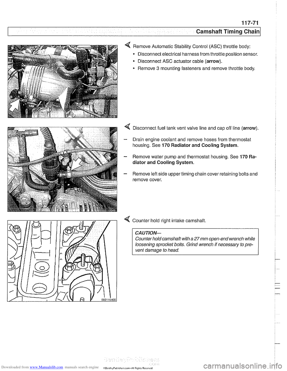
< Remove Automatic Stability Control (ASC) throttle body:
Disconnect electrical harness from throttle position sensor.
Disconnect ASC actuator cable (arrow).
Remove
3 mounting fasteners and remove throttle body.
4 Disconnect fuel tank vent valve line and cap off line (arrow).
- Drain engine coolant and remove hoses from thermostat
housing. See
170 Radiator and Cooling System.
- Remove water pump and thermostat housing. See 170 Ra-
diator and Cooling System.
- Remove left side upper timing chain cover retaining bolts and
remove cover.
4 Counter hold right intake camshaft
CAUTION-
Counter hold camshaft with a 27mm open-end wrench while
loosening sprocket bolts. Grind wrench if necessary to pre-
vent damage to head.
Page 312 of 1002
Downloaded from www.Manualslib.com manuals search engine
1 17-76
/camshaft Timing Chain
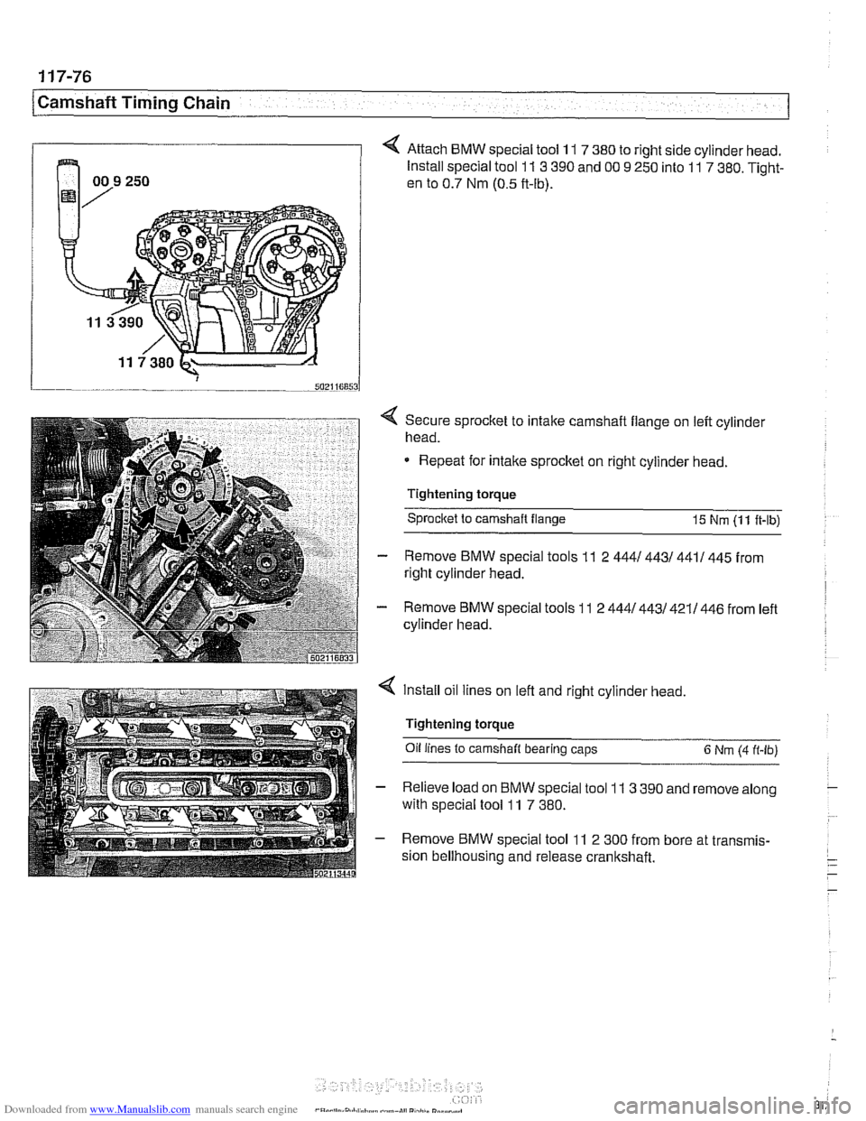
4 Attach BMW special tool 11 7 380 to right side cylinder head.
Install special tool
11 3 390 and 00 9 250 into 11 7 380. Tight-
en to 0.7 Nm (0.5 ft-lb).
4 Secure sprocket to intake camshaft flange on left cylinder
head.
Repeat for intake sprocket on right cylinder head.
Tightening torque Sprocltet to camshaft flange
15 Nm (1 1 ft-lb)
- Remove BMW special tools 11 2 4441 4431 4411 445 from
right cylinder head.
- Remove BMW special tools 11 2 4441443/421/446 from left
cylinder head.
4 Install oil lines on left and right cylinder head,
Tightening torque
Oil
lines to camshaft bearing caps 6 Nm (4 ft-lb)
- Relieve load on BMW special tool 11 3 390 and remove along
with special tool
11 7 380.
- Remove BMW special tool 11 2 300 from bore at transmis-
sion bellhousing and release crankshaft.
Page 314 of 1002
Downloaded from www.Manualslib.com manuals search engine
[camshaft Timina Chain
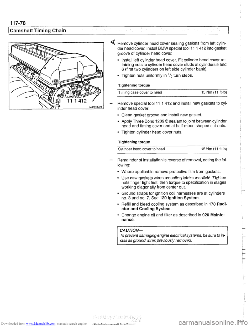
< Remove cylinder head cover sealing gaskets from lefl cylin-
der head cover. Install
BMW special tool 11 1 412 into gasket
groove of cylinder head cover.
Install lefl cylinder head cover. Fit cylinder head cover re-
taining nuts to cylinder head cover studs at cylinders
5 and
6 (first two cylinders on left side cylinder bank).
Tighten nuts uniformly in
'I2 turn steps
Tightening torque
Timing case cover to head
15 Nm (1 1 ft-lb)
- Remove special tool 11 1 41 2 and install new gaskets to cyl-
inder head cover:
Clean gasket groove and install new gasket.
Apply Three Bond
12098sealant tojoint between cylinder
head and timing cover and at half-moon shaped cut-outs.
Tighten cylinder head cover nuts.
Tightening torque Cylinder head cover to head
I5 Nm (1 1 ft-lb)
- Remainder of installation is reverse of removal, noting the fol-
lowing:
Where applicable remove protective film from gaskets.
Use new gaskets when mounting intake manifold. Tighten
nuts finger tight first, then torque to specification in stages
worlting diagonally from center out.
Ground straps for ignition coil harnesses are at cylinders
no.
3 and no. 7. See 120 Ignition System.
Refill and bleed cooling system as described in
170 Radi-
ator and Cooling System.
Change engine oil and filter as described in
020 Mainte-
nance.
CAUTIOI\C
To prevent damaging engine electrical systems, be sure to in-
stall ail ground wires previously removed.
Page 315 of 1002
Downloaded from www.Manualslib.com manuals search engine
Camshaft Timing chain/
Camshaft timing, checking and adjusting
(M62 engine)
WARNING -
Allow engine to cool before beginning this procedure. 1
- Working inside luggage compartment, disconnect negative
battery cable.
CAUTIOI\C
Prior to disconnecting battery cable, read the battery discon-
nection cautions given
in 001 General Cautions and
Warninss.
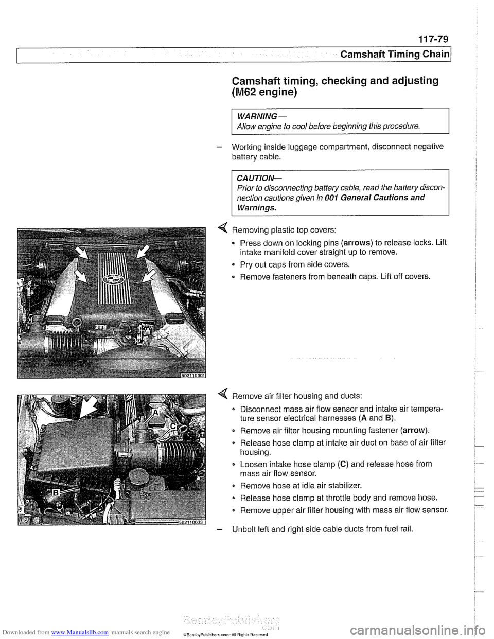
4 Removing plastic top covers:
Press down on locking pins (arrows) to release locks. Lift
intake manifold cover straight up to remove.
Pry out caps from side covers.
Remove fasteners from beneath
caDs. Lift off covers.
4 Remove air filter housing and ducts:
Disconnect mass air flow sensor and intake air tempera-
ture sensor electrical harnesses
(A and B).
Remove air filter housing mounting fastener (arrow).
Release hose clamp at intake air duct on base of air filter
housing.
Loosen intake hose clamp
(C) and release hose from
mass air flow sensor.
Remove hose at idle air stabilizer.
Release hose clamp at throttle body and remove hose.
Remove upper air filter housing with mass air flow sensor.
- Unbolt left and right side cable ducts from fuel rail.
Page 316 of 1002
Downloaded from www.Manualslib.com manuals search engine
Camshaft Timing Chain LL. .- - - - I
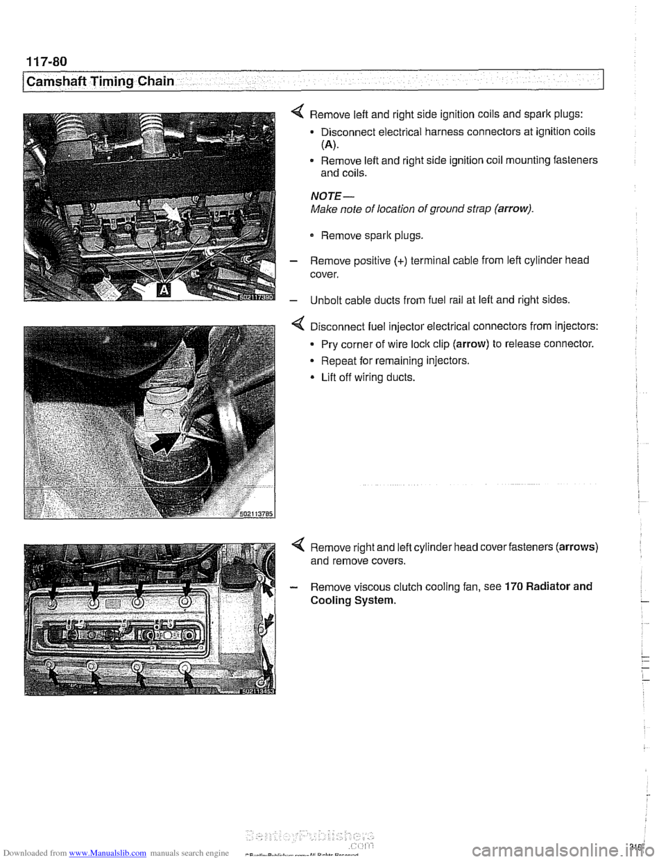
4 Remove left and right side ignition coils and spark plugs:
- Disconnect electrical harness connectors at ignition coils
(A).
Remove left and right side ignition coil mounting fasteners
and coils.
NOTE-
Make note of location of ground strap (arrow).
Remove sparlc plugs.
- Remove positive (+) terminal cable from left cylinder head
cover.
- Unbolt cable ducts from fuel rail at left and right sides.
Disconnect fuel injector electrical connectors from injectors:
Pry corner of wire
loclc clip (arrow) to release connector.
Repeat for remaining injectors.
* Lift off wiring ducts.
Page 324 of 1002
Downloaded from www.Manualslib.com manuals search engine
-
I Lubrication System - I
Oil pressure, checking
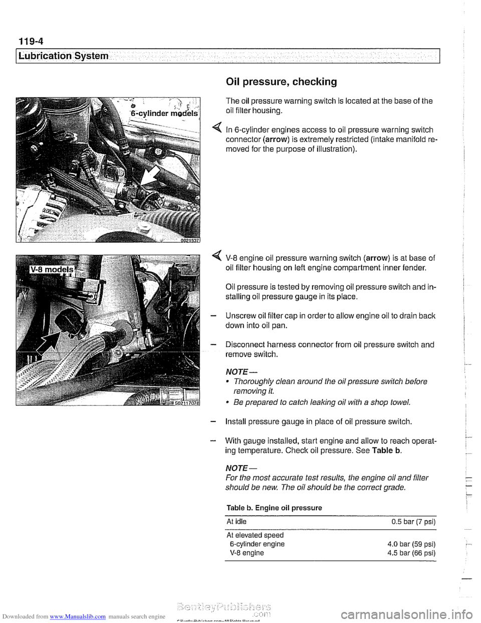
The oil pressure warning switch is located at the base of the
oil filter housing.
In 6-cylinder engines access to oil pressure warning switch
connector (arrow) is extremely restricted (intake manifold re.
moved for the purpose of illustration).
V-8 engine oil pressure warning switch (arrow) is at base of
oil filter housing on left engine compartment inner fender.
Oil pressure is tested by removing oil pressure switch and in-
stalling oil pressure gauge in its place.
Unscrew oil filter cap in order to allow engine oil to drain back
down into oil pan.
Disconnect harness connector from oil pressure switch and
remove switch.
NOJE-
Thoroughly clean around the oil pressure switch before
removing it.
Be prepared to catch leaking oil with a shop towel.
- Install pressure gauge in place of oil pressure switch,
- With gauge installed, start engine and allow to reach operat-
ing temperature. Check oil pressure. See Table b.
NOJE-
For the most accurate test results, the engine oil and filter
should be new. The oil should be the correct grade.
Table b. Engine oil pressure
At idle 0.5 bar (7 psi)
At elevated speed
6-cylinder engine 4.0 bar
(59 psi)
V-8 engine 4.5 bar (66 psi)
Page 325 of 1002
Downloaded from www.Manualslib.com manuals search engine
. .- -
L
- --
- - -. - -- Lubrication ~~stern
- Remove pressure gauge and reinstall pressure switch with
new sealing washer.
Tightening torque
Oil pressure switch to oil filter housing 27 Nm (20 ft-lb)
If testing shows low oil pressure, one or more of the following
conditions may be indicated:
Worn or faulty oil pump or faulty pump pressure relief valve
Worn or damaged engine bearings
Severe engine wear
Any of these conditions indicate the need for major repairs.
Oil pressure warning system, testing
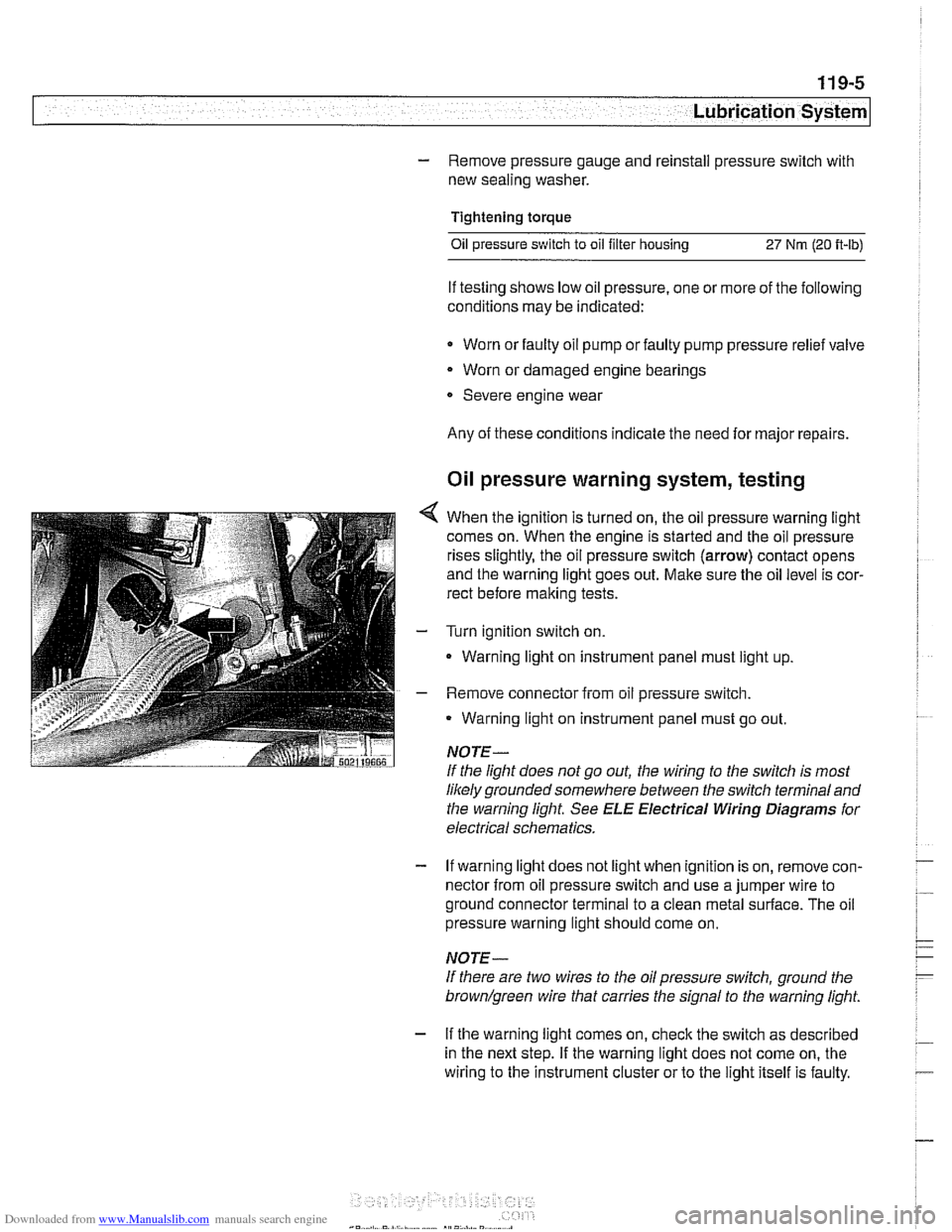
4 When the ignition is turned on, the oil pressure warning light
comes on. When the engine is started and the oil pressure
rises slightly, the oil pressure switch (arrow) contact opens
and the warning light goes out. Make sure the oil level is cor-
rect before making tests.
- Turn ignition switch on.
- Warning light on instrument panel must light up
- Remove connector from oil pressure switch.
Warning light on instrument panel must go out.
NOTE-
If the light does not go out, the wiring to the switch is most
likely grounded somewhere between the switch terminaland
the warning light See
ELE Electrical Wiring Diagrams for
electrical schematics.
- If warning light does not light when ignition is on, remove con-
nector from oil pressure switch and use a jumper wire to
ground connector terminal to a clean metal surface. The oil
pressure warning light should come on.
NOTE-
If there are two wires to the oil pressure switch, ground the
brown/green wire that carries the signal to the warning light.
- If the warning light comes on, check the switch as described
in the next step. If the warning light does not come on, the
wiring to the instrument cluster or to the light itself is faulty.
Page 331 of 1002
Downloaded from www.Manualslib.com manuals search engine
Lubrication system/
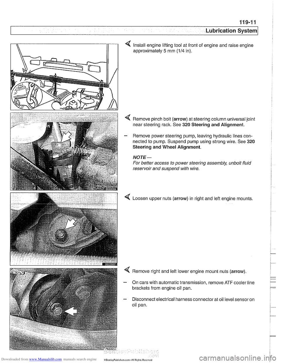
4 Install engine lifting tool at front of engine and raise engine
approximately
5 mm (114 in).
< Remove pinch bolt (arrow) at steering column universal joint
near steering rack. See
320 Steering and Alignment.
- Remove power steering pump, leaving hydraulic lines con-
nected to pump. Suspend pump using strong wire. See
320
Steering and Wheel Alignment.
NOTE-
For better access to power steering assembly, unbolt fluid
reservoir and suspend with wire.
Loosen upper nuts (arrow) in right and lefl engine mounts,
< Remove right and left lower engine mount nuts (arrow)
- On cars with automatic transmission, remove ATF cooler line
brackets from engine oil pan.
- Disconnect electrical harness connector at oil level sensor on
oil pan.
Page 334 of 1002
Downloaded from www.Manualslib.com manuals search engine
.
[Lubrication System
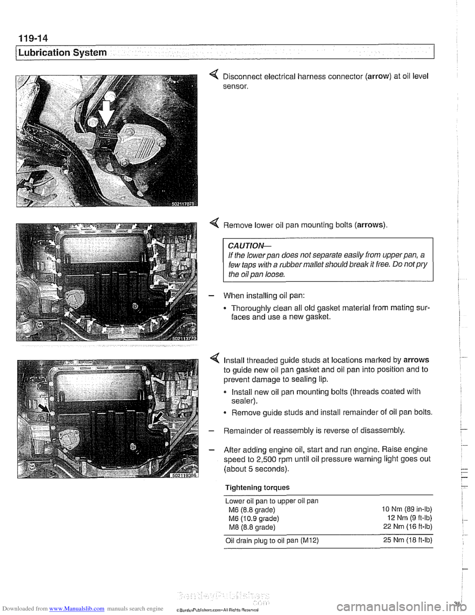
< Disconnect electrical harness connector (arrow) at oil level
sensor.
< Remove lower oil pan mounting bolts (arrows)
CAUTIOI\C
If the lowerpan does not separate easily from upperpan, a
few taps with a rubber mallet should break it free. Do
notpry
the oil pan loose.
- When installing oil pan:
Thoroughly clean all old
gasltet material from mating sur-
faces and use a new gasket.
4 Install threaded guide studs at locations marked by arrows
to guide new oil pan
gasltet and oil pan into position and to
prevent damage to sealing lip.
- Install new oil pan mounting bolts (threads coated with
sealer).
Remove guide studs and install remainder of oil pan bolts.
- Remainder of reassembly is reverse of disassembly
- After adding engine oil, start and run engine. Raise engine
speed to 2,500 rpm until oil pressure warning light goes out
(about 5 seconds).
Tightening torques Lower oil pan to upper
oil pan
M6 (8.8 grade) 10 Nm (89 in-lb)
M6 (10.9 grade) 12 Nm (9 ft-lb)
M8 (8.8 grade) 22 Nm (16 ft-lb)
Oil drain plug to oil pan (M12) 25 Nm (18 ft-lb)