start electrical BMW 528i 1999 E39 User Guide
[x] Cancel search | Manufacturer: BMW, Model Year: 1999, Model line: 528i, Model: BMW 528i 1999 E39Pages: 1002
Page 92 of 1002
Downloaded from www.Manualslib.com manuals search engine
11 0-20
Engine Removal and Installation
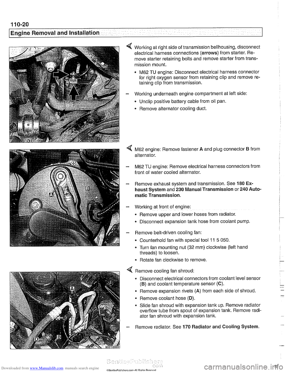
Working at right side of transmission bellhousing, disconnect
electrical harness connections (arrows) from starter. Re-
move starter retaining bolts and remove starter from trans-
mission mount.
M62 TU engine: Disconnect electrical harness connector
for right oxygen sensor from retaining clip and remove re-
taining clip from transmission.
- Working underneath engine compartment at left side:
Unclip positive battery cable from oil pan.
. Remove alternator cooling duct.
4 M62 engine: Remove fastener A and plug connector B from
alternator.
- M62 TU engine: Remove electrical harness connectors from
front of water cooled alternator.
- Remove exhaust system and transmission. See 180 Ex-
haust System and 230 Manual Transmission or 240 Auto-
matic Transmission.
- Working at front of engine:
Remove upper and lower hoses from radiator.
D~sconnect expansion tank hose from coolant pump.
- Remove belt-driven cooling fan:
Counterhold fan with special tool
11 5 050.
Turn fan mounting nut (32 mm) clockwise (left hand
threads) to loosen.
Rotate fan clockwise to remove.
Remove cooling fan shroud:
Disconnect electrical connectors from coolant level sensor
(B) and coolant temperature sensor (C).
. Remove expansion rivets (A) from each side of shroud
Remove coolant hose
(D).
Slide fan shroud with expansion tank up. Remove radiator
overflow tube from spout of expansion tank. Remove radi-
ator fan shroud with expansion tank.
Remove radiator. See
170 Radiator and Cooling System.
Page 185 of 1002
Downloaded from www.Manualslib.com manuals search engine
11 6-9
Cvlinder Head and valvetrain1
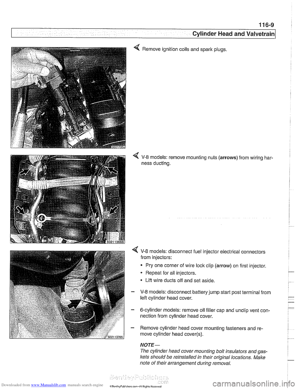
4 Remove ignition coils and spark plugs.
V-8 models: remove mounting nuts (arrows) from wiring har-
ness ducting.
< V-8 models: disconnect fuel injector electrical connectors
from injectors:
Pry one corner of wire
loclc clip (arrow) on first injector.
Repeat for all injectors.
Lift wire ducts off and set aside.
- V-8 models: disconnect battery jump start post terminal from
left cylinder head cover.
- 6-cylinder models: remove oil filler cap and unclip vent con-
nection from cylinder head cover.
- Remove cylinder head cover mounting fasteners and re-
move cylinder head cover(~).
NOTE-
The cylinder head cover mounting bolt insulators and gas-
Icets should be reinstalled in their original locations. Make
note of their arrangement
during removal.
Page 258 of 1002
Downloaded from www.Manualslib.com manuals search engine
Camshaft Timing Chain
VANOS timing, checking and adjusting
(M52 engine)
NOTE-
* Special BMW service tools are required to remove and in-
stall the VANOS control unit. Read the procedure through
before starting the job.
If the camshafts are not properly timed, the pistons can
contact the valves.
- Disconnect negative (-) cable from battery.
CAUTIOG Disconnecting the battery may erase
faultcode(s) storedin
control module memory. Prior to disconnecting the battery,
checlc for fault codes using special BMW diagnostic equip-
ment.
Prior to disconnecting the battery, read the battery dis-
connection cautions given in
001 General Cautions
and Warnings.
- Remove viscous clutch cooling fan. See 170 Radiator and
Cooling
System.
CAUTIOG The radiator cooling fan nut
(32 mm wrench) has left-hand
threads.
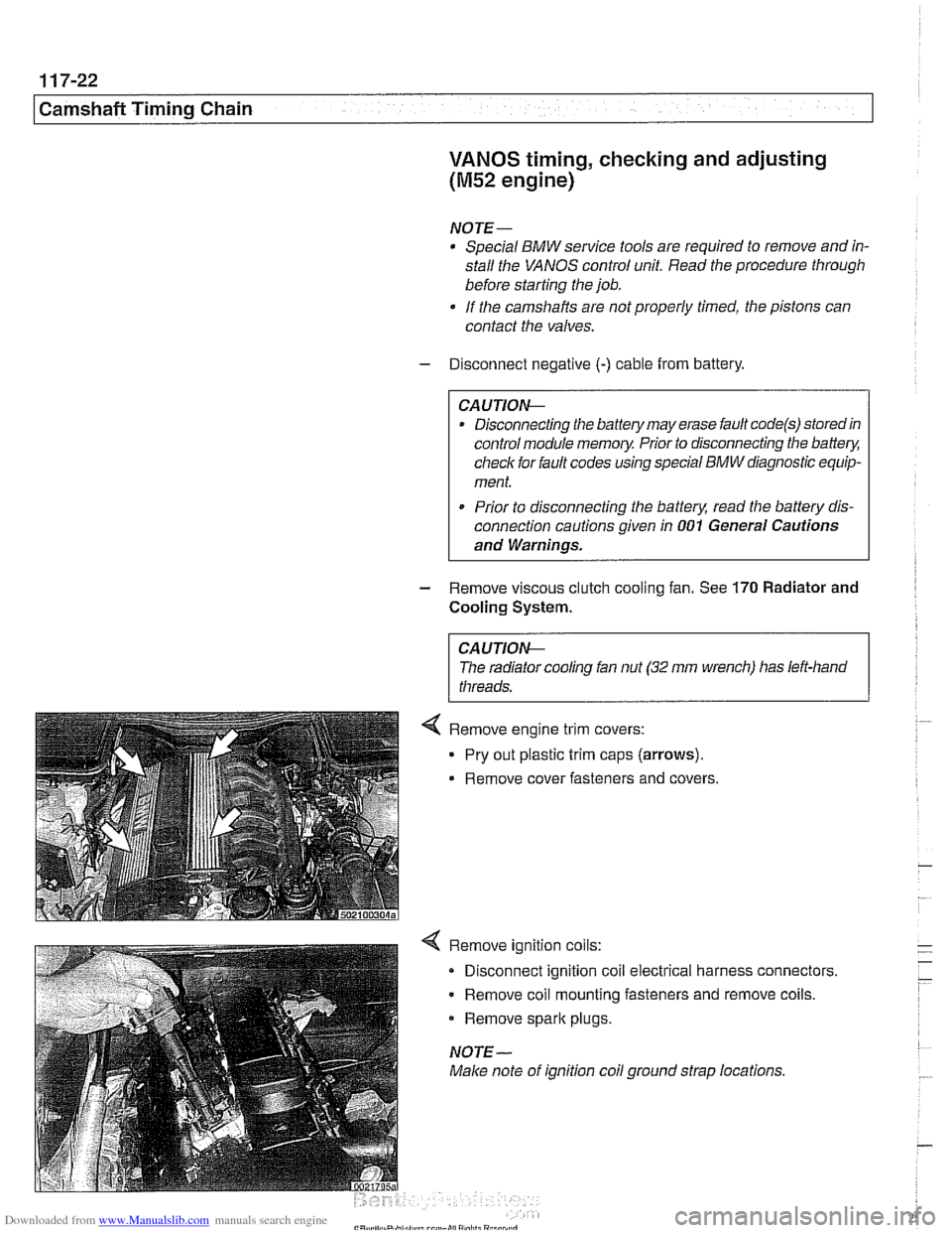
4 Remove ignition coils:
Disconnect ignition coil electrical harness connectors.
Remove coil mounting fasteners and remove coils.
Remove
spark plugs.
NOTE-
Make note of ignition coil ground strap locations.
Page 325 of 1002
Downloaded from www.Manualslib.com manuals search engine
. .- -
L
- --
- - -. - -- Lubrication ~~stern
- Remove pressure gauge and reinstall pressure switch with
new sealing washer.
Tightening torque
Oil pressure switch to oil filter housing 27 Nm (20 ft-lb)
If testing shows low oil pressure, one or more of the following
conditions may be indicated:
Worn or faulty oil pump or faulty pump pressure relief valve
Worn or damaged engine bearings
Severe engine wear
Any of these conditions indicate the need for major repairs.
Oil pressure warning system, testing
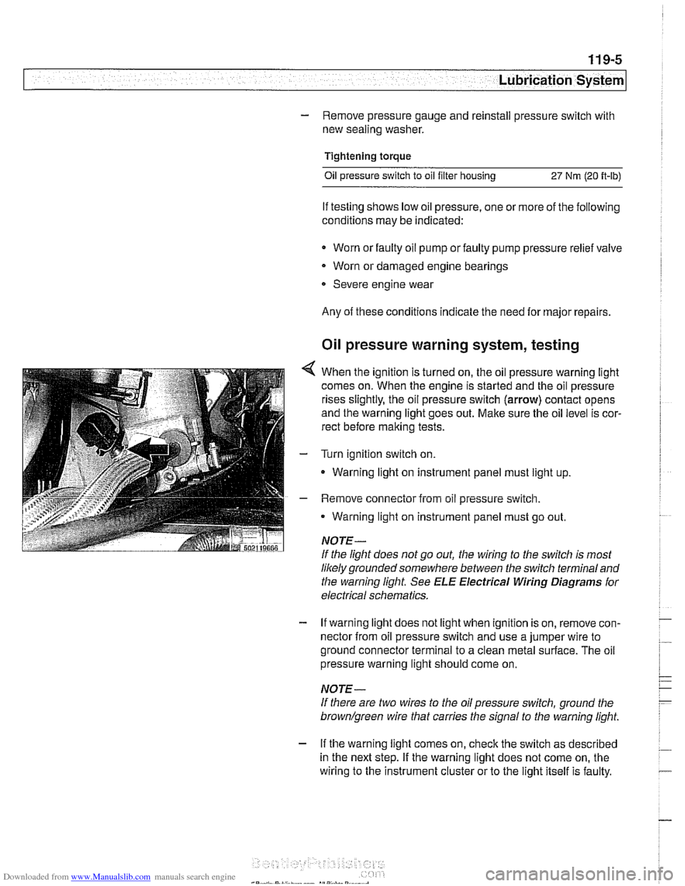
4 When the ignition is turned on, the oil pressure warning light
comes on. When the engine is started and the oil pressure
rises slightly, the oil pressure switch (arrow) contact opens
and the warning light goes out. Make sure the oil level is cor-
rect before making tests.
- Turn ignition switch on.
- Warning light on instrument panel must light up
- Remove connector from oil pressure switch.
Warning light on instrument panel must go out.
NOTE-
If the light does not go out, the wiring to the switch is most
likely grounded somewhere between the switch terminaland
the warning light See
ELE Electrical Wiring Diagrams for
electrical schematics.
- If warning light does not light when ignition is on, remove con-
nector from oil pressure switch and use a jumper wire to
ground connector terminal to a clean metal surface. The oil
pressure warning light should come on.
NOTE-
If there are two wires to the oil pressure switch, ground the
brown/green wire that carries the signal to the warning light.
- If the warning light comes on, check the switch as described
in the next step. If the warning light does not come on, the
wiring to the instrument cluster or to the light itself is faulty.
Page 334 of 1002
Downloaded from www.Manualslib.com manuals search engine
.
[Lubrication System
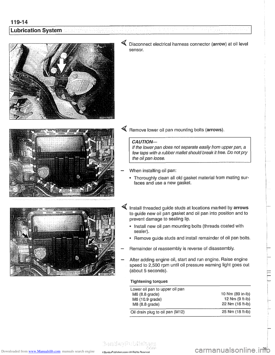
< Disconnect electrical harness connector (arrow) at oil level
sensor.
< Remove lower oil pan mounting bolts (arrows)
CAUTIOI\C
If the lowerpan does not separate easily from upperpan, a
few taps with a rubber mallet should break it free. Do
notpry
the oil pan loose.
- When installing oil pan:
Thoroughly clean all old
gasltet material from mating sur-
faces and use a new gasket.
4 Install threaded guide studs at locations marked by arrows
to guide new oil pan
gasltet and oil pan into position and to
prevent damage to sealing lip.
- Install new oil pan mounting bolts (threads coated with
sealer).
Remove guide studs and install remainder of oil pan bolts.
- Remainder of reassembly is reverse of disassembly
- After adding engine oil, start and run engine. Raise engine
speed to 2,500 rpm until oil pressure warning light goes out
(about 5 seconds).
Tightening torques Lower oil pan to upper
oil pan
M6 (8.8 grade) 10 Nm (89 in-lb)
M6 (10.9 grade) 12 Nm (9 ft-lb)
M8 (8.8 grade) 22 Nm (16 ft-lb)
Oil drain plug to oil pan (M12) 25 Nm (18 ft-lb)
Page 353 of 1002
Downloaded from www.Manualslib.com manuals search engine
Lnition switch
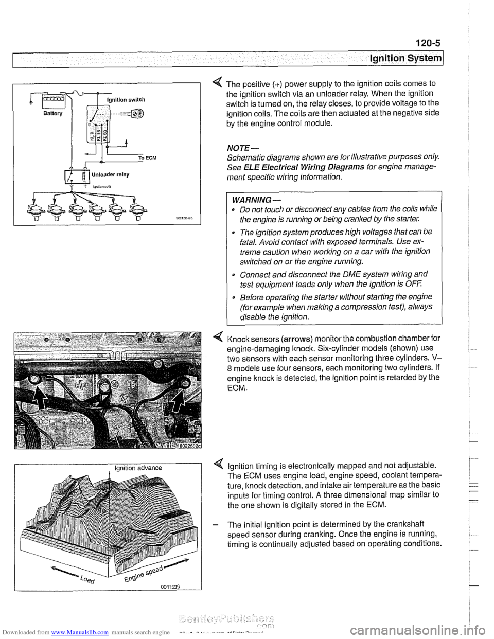
4 The positive (+) power supply to the ignition coils comes to
the ignition switch via an unloader relay. When the ignition
switch is turned on, the relay closes, to provide voltage to the
ignition coils. The coils are then actuated at the negative side
by the engine control module.
NOTE-
Schematic diagrams shown are for illustrative purposes only.
See ELE Electrical Wiring Diagrams for engine manage-
ment specific wiring information.
WARNING- Do not touch or disconnect any cables from the coils while
the engine is running or being cranked by the starter:
The ignition system produces high voltages that can be
fatal. Avoid contact with exposed terminals. Use ex-
treme caution when
working on a car with the ignition
switched on or the engine running.
* Connect and disconnect the DME system wiring and
test equipment leads only when the ignition is
OFF
Before operating the starter without starting the engine
(for example when
making a compression test), always
disable the ignition.
4 Knock sensors (arrows) monitor the combustion chamber for
engine-damaging knock. Six-cylinder models (shown) use
two sensors with each sensor monitoring three cylinders.
V-
8 models use four sensors, each monitoring two cylinders. If
engine
knock is detected, the ignition point is retarded by the
ECM.
I Ignition advance Ignition timing is electronically mapped and not adjustable.
The ECM uses engine load, engine speed, coolant tempera-
ture, knock detection, and intake air temperature as the basic
inputs for timing control.
A three dimensional map similar to
the one shown is digitally stored in the ECM.
- The initial ignition point is determined by the crankshaft
speed sensor during cranking. Once the engine is running.
timing is continually adjusted based on operating conditions.
Page 359 of 1002
Downloaded from www.Manualslib.com manuals search engine
Ignition System
- Turn ignition on and check for battery voltage,
If battery voltage is not present,
checlt wire between termi-
nal
15 and the unloader relay. See ELE Electrical Wiring
Diagrams.
- Turn ignition off.
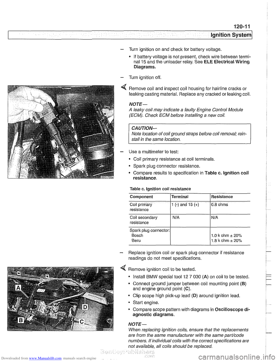
Remove coil and inspect coil housing for hairline
cracks or
leaking casting material. Replace any
cracked or leaking coil.
NOTE-
A leaky coil may indicate a faulty Engine Control Module
(ECM). Check ECM before installing a new coil.
CAUTION-
Note location of coilground straps before coil removal; rein-
stall in the same location.
Use a multimeter to test:
Coil primary resistance at coil terminals.
Sparlt plug connector resistance.
* Compare results to specification in Table c. lgnition coil
resistance.
Table c. Ignition coil resistance
Coil secondary
resistance
Spark plug connector:
Bosch 1 .O I( ohm t 20%
1.8 ir ohm t 20%
Component
Co~l prlmary
resistance
- Replace ignition coil or sparlt plug connector if resistance
readings do not meet specifications.
4 Remove ignition coil to be tested.
Install
BMW special tool 12 7 030 (A) on coil to be tested.
Connect ground jumper between coil mounting point
(B)
and engine ground point (C).
Clip scope high pick-up lead (D) around ignition lead.
Start engine.
Compare scope pattern with diagrams in Oscilloscope
di-
agnostic diagrams.
NOTE-
When replacing ignition coils, ensure that the replacements
Terminal
1 (-) and 15 (+)
are
from the same manufacturer with the same partlcode
numbers. If individual coils with the correct specifications are
not available. all coils should be
re~laced.
Resistance
0.8 ohms
Page 361 of 1002
Downloaded from www.Manualslib.com manuals search engine
ignition System
Crankshaft speed sensor, replacing (M62 and M62TU
engines)
The crankshaft speed sensor reads a toothed pulse wheel
mounted on the flywheel.
If the Engine Control Module(ECM)
does not receive an impulse signal from the crankshaft speed
sensor during
cranking, the engine will not start. If the OBD II
system misfire detection protocol detects a catalyst damag-
ing fault due to a malfunction in the crankshaft speed sensor
components, the Check Engine light (Malfunction
Indicator
Light or MIL) will be Illuminated.
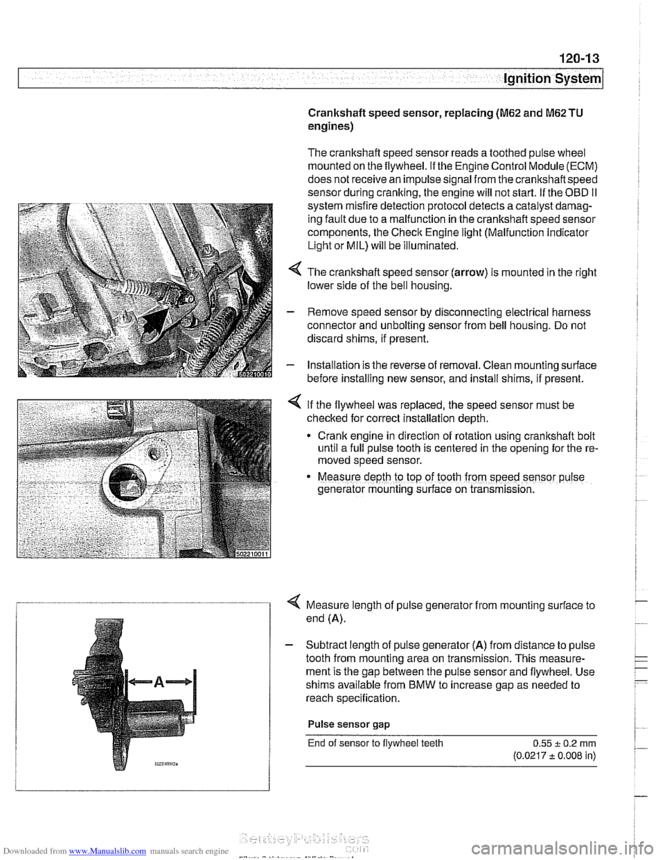
4 The crankshaft speed sensor (arrow) is mounted in the right
lower side of the bell housing.
- Remove speed sensor by disconnecting electrical harness
connector and unbolting sensor from bell housing. Do not
discard shims, if present.
- Installation is the reverse of removal. Clean mounting surface
before installing new sensor, and install shims, if present.
< If the flywheel was replaced, the speed sensor must be
checked for correct installation depth.
* Crank engine in direction of rotation using crankshaft bolt
until a full pulse tooth is centered in the opening for the re-
moved speed sensor.
Measure depth ro top of tooth from speed sensor p~lse
generator mounting s~rface on transmission.
4 Measure length of pulse generator from mounting surface to
end (A).
- Subtract length of pulse generator (A) from distance to pulse
tooth from mounting area on transmission. This measure-
ment is the gap between the pulse sensor and flywheel. Use
shims available from BMW to increase gap as needed to
reach specification.
Pulse sensor
gap
End of sensor to flywheel teeth 0.55 + 0.2 rnrn
(0.0217 t 0.008 in)
Page 367 of 1002
Downloaded from www.Manualslib.com manuals search engine
121-1
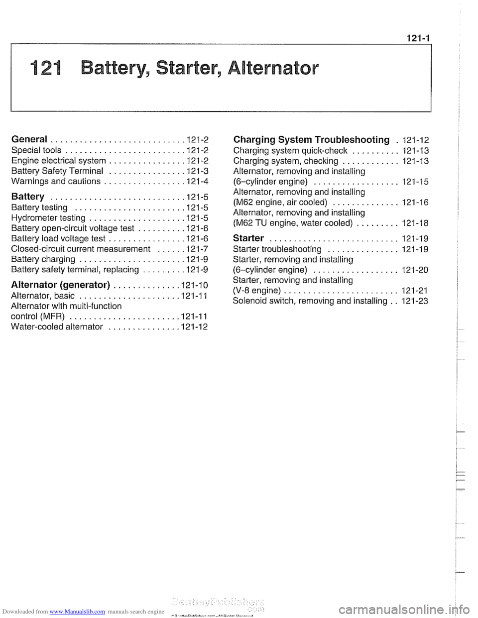
121 Battery. Starter. Alternator
General ........................... .I2 1.2
Special tools ........................ .I2 1.2
Engine electrical system ............... .I2 1.2
Battery Safety Terminal ............... .I2 1.3
Warnings and cautions ................. 121 -4
Battery ............................ 121-5
Battery testing ...................... .I2 1.5
Hydrometer testing ................... .I2 1.5
Battery open-circuit voltage test ......... .I2 1.6
Battery load voltage test ................ 121 -6
Closed-circuit current measurement ..... .I2 1.7
Battery charging ...................... 121 -9
Battery safety terminal, replacing ......... 121-9
Alternator (generator) ............. .I2 1.10
Alternator. basic .................... .I2 1.11
Alternator with multi-function
control (MFR)
...................... .I2 1.11
Water-cooled alternator ............... 121 -12
Charging System Troubleshooting . 121-12
Charging system quick-check .......... 121-13
Charging system. checking ............ 121-13
Alternator. removing and installing
(6-cylinder engine)
.................. 121 -1 5
Alternator. removing and installing
(M62 engine. air cooled)
.............. 121-16
Alternator. removing and installing
(M62 TU engine. water cooled) ......... 121-1 8
Starter ........................... 121 -1 9
Starter troubleshooting ............... 121 -1 9
Starter. removing and installing
(6-cylinder engine)
.................. 121-20
Starter. removing and installing
(V-8 engine)
........................ 121 -21
Solenoid switch. removing and installing . . 121-23
Page 368 of 1002
Downloaded from www.Manualslib.com manuals search engine
- -
Battery, Starter, Alternator
This section covers the battery, alternator, starter and associ-
ated components of the electrical system.
Troubleshooting information
forthese components isfound in
Table a. Battery, alternator and starter troubleshooting.
For additional electrical troubleshooting information, see
600 Electrical System-General.
Special tools
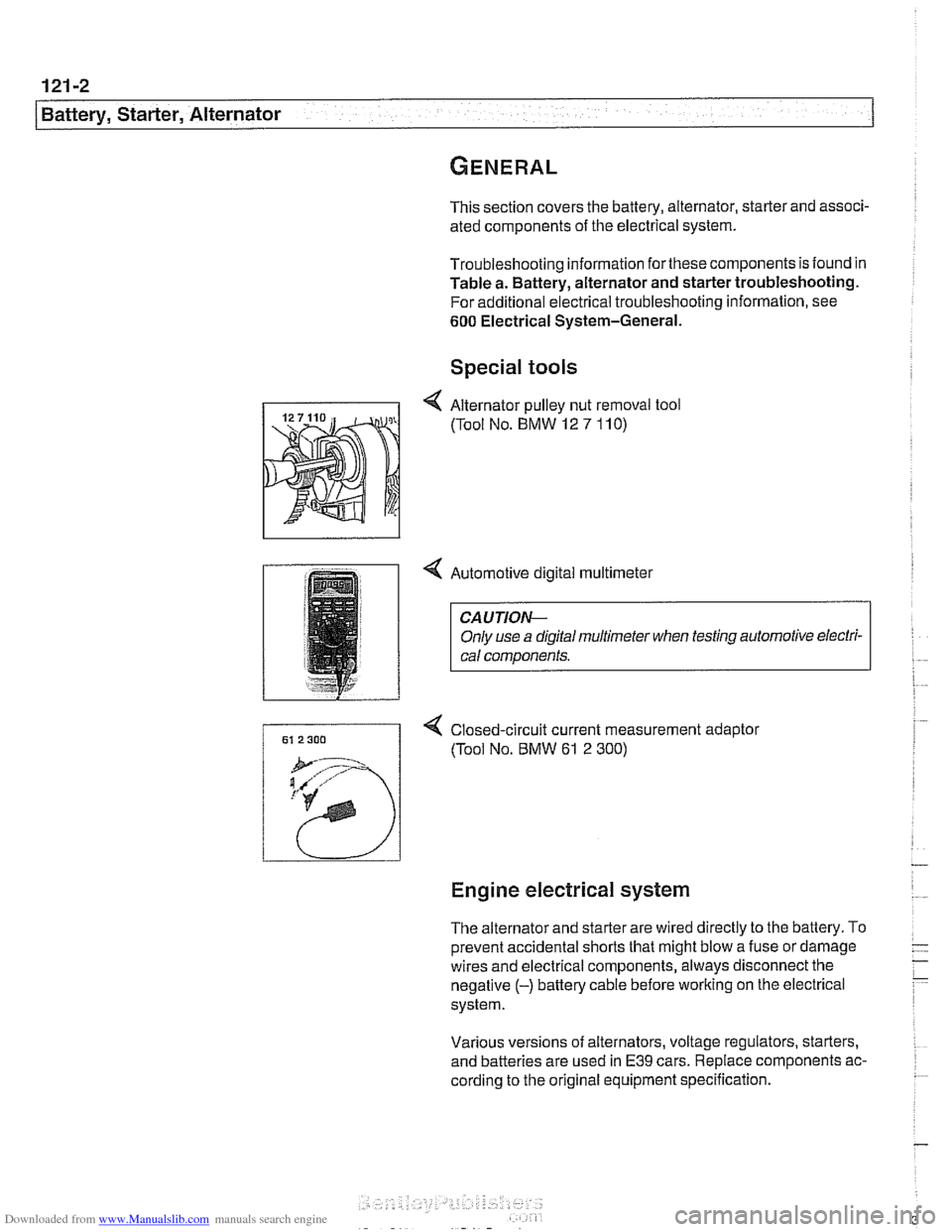
4 Automotive digital multimeter
CAUTION-
Only use a digital multirneter when testing automotive electri- I) cal components.
4 Closed-circuit current measurement adaptor
(Tool No.
BMW 61 2 300)
Engine electrical system
The alternator and starter are wired directly to the battery. To
prevent accidental shorts that might blow a fuse or damage
wires and electrical components, always disconnect the
negative
(-) battery cable before working on the electrical
system.
Various versions of alternators, voltage regulators, starters,
and batteries are used in
E39 cars. Replace components ac-
cording to the original equipment specification.