temp sensor BMW 528i 1999 E39 User Guide
[x] Cancel search | Manufacturer: BMW, Model Year: 1999, Model line: 528i, Model: BMW 528i 1999 E39Pages: 1002
Page 270 of 1002
Downloaded from www.Manualslib.com manuals search engine
1 17-34
1 Camshaft Timing Chain
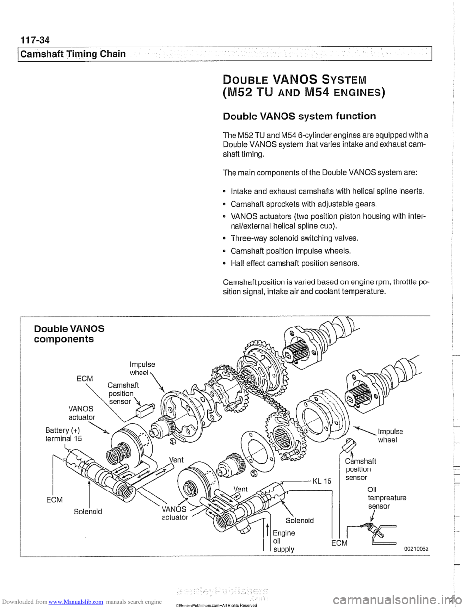
DOUBLE VAMOS SYSTEM
(M52 TU AND M54 ENGINES)
Double VANOS system function
The M52TU and M54 6-cylinder engines are equipped with a
Double VANOS system that varies intake and exhaust cam-
shaft timing.
The main components of the Double VANOS system are:
lntalte and exhaust camshafts with helical spline inserts.
Camshaft sprockets with adjustable gears.
VANOS actuators (two position piston housing with
inter-
nallexternal helical spline cup).
Three-way solenoid switching valves.
Camshaft position impulse wheels.
Hall effect camshaft position sensors.
Camshaft position
IS varied based on engine rpm, throttle po-
sition signal, intake air and coolant temperature.
Page 303 of 1002
Downloaded from www.Manualslib.com manuals search engine
Camshaft Timing chain1
- Disconnect negative cable (-) from battery.
CAUTION-
Prior to disconnecting the battery, read the battery discon-
nection cautions given
in 001 General Cautions and
Warnings.
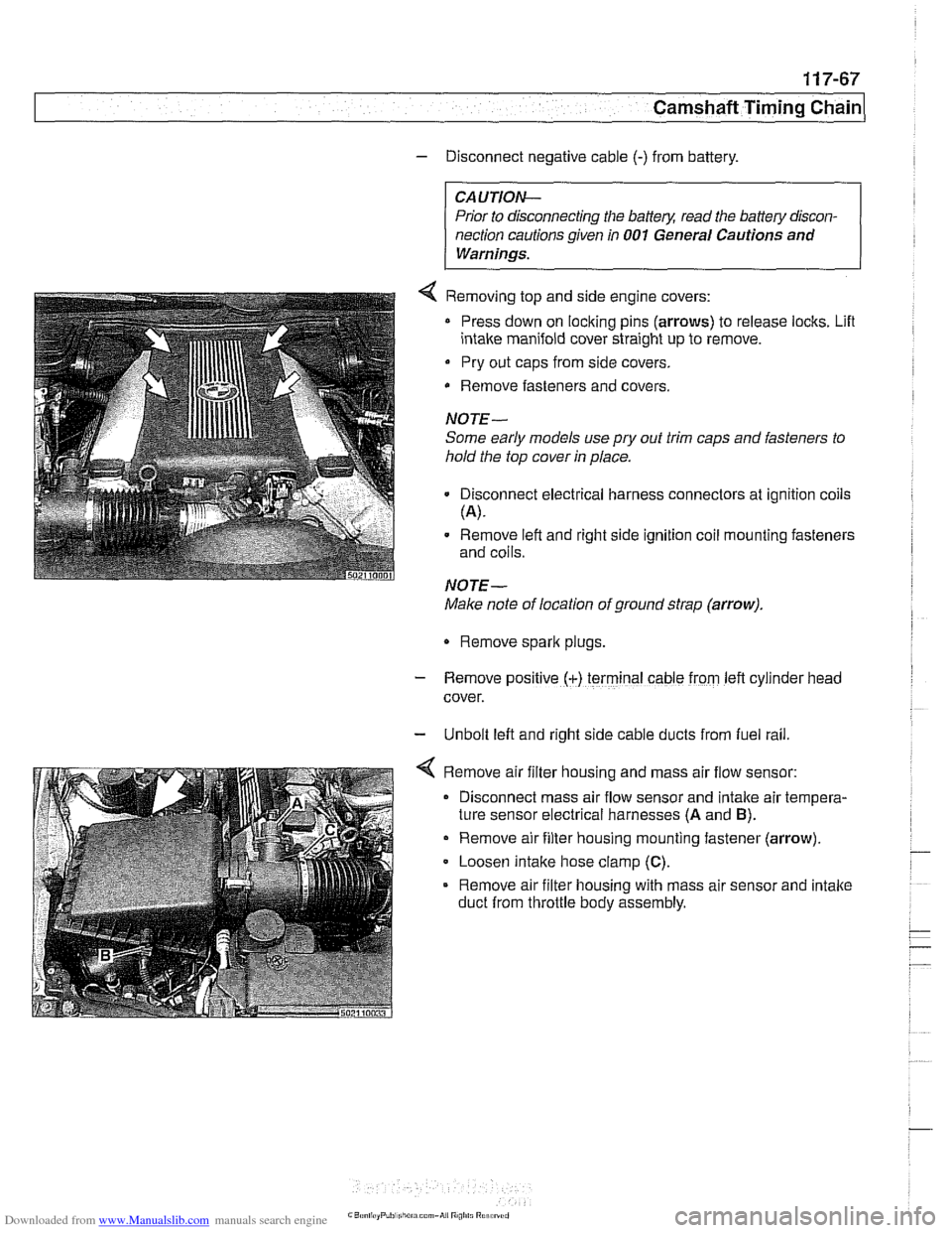
4 Removing top and side engine covers:
Press down on locking pins (arrows) to release locks. Lifl
intake manifold cover straight up to remove.
Pry out caps from side covers.
Remove fasteners
and covers.
NOTE-
Some early models use
pry out trim caps and fasteners to
hold the top cover in place.
Disconnect electrical harness connectors at ignition coils
(A).
Remove left and right side ignition coil mounting fasteners
and coils.
NOTE-
Make note of location of ground strap (arrow).
Remove spark plugs.
- Remove posltlve (+) terminal cable from left cylrnder head
cover.
- Unbolt left and right side cable ducts from fuel rail
Remove air filter housing and mass air flow sensor:
Disconnect mass air flow sensor and intake air tempera-
ture sensor electrical harnesses
(A and B).
Remove air filter housing mounting fastener (arrow)
Loosen intake hose clamp
(C).
Remove air filter housing with mass air sensor and intake
duct from throttle body assembly.
Page 315 of 1002
Downloaded from www.Manualslib.com manuals search engine
Camshaft Timing chain/
Camshaft timing, checking and adjusting
(M62 engine)
WARNING -
Allow engine to cool before beginning this procedure. 1
- Working inside luggage compartment, disconnect negative
battery cable.
CAUTIOI\C
Prior to disconnecting battery cable, read the battery discon-
nection cautions given
in 001 General Cautions and
Warninss.
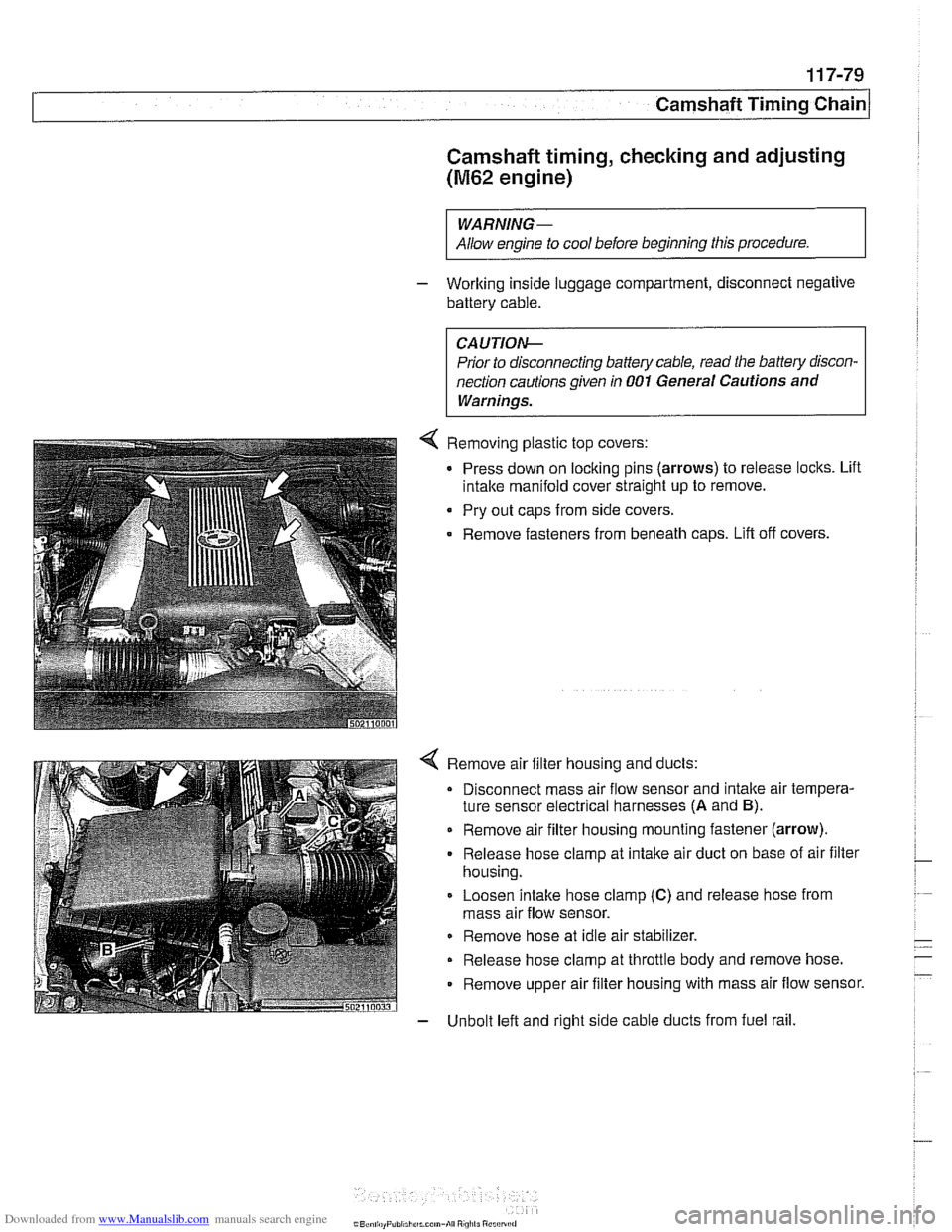
4 Removing plastic top covers:
Press down on locking pins (arrows) to release locks. Lift
intake manifold cover straight up to remove.
Pry out caps from side covers.
Remove fasteners from beneath
caDs. Lift off covers.
4 Remove air filter housing and ducts:
Disconnect mass air flow sensor and intake air tempera-
ture sensor electrical harnesses
(A and B).
Remove air filter housing mounting fastener (arrow).
Release hose clamp at intake air duct on base of air filter
housing.
Loosen intake hose clamp
(C) and release hose from
mass air flow sensor.
Remove hose at idle air stabilizer.
Release hose clamp at throttle body and remove hose.
Remove upper air filter housing with mass air flow sensor.
- Unbolt left and right side cable ducts from fuel rail.
Page 335 of 1002
Downloaded from www.Manualslib.com manuals search engine
... . . Lubrication sy=
Upper oil pan, removing and installing (V-8)
The engine oil pan removal procedure requires that the en-
gine be supported from the top and the front suspension
sub-
frame be lowered.
- Disconnect negative (-) battery cable
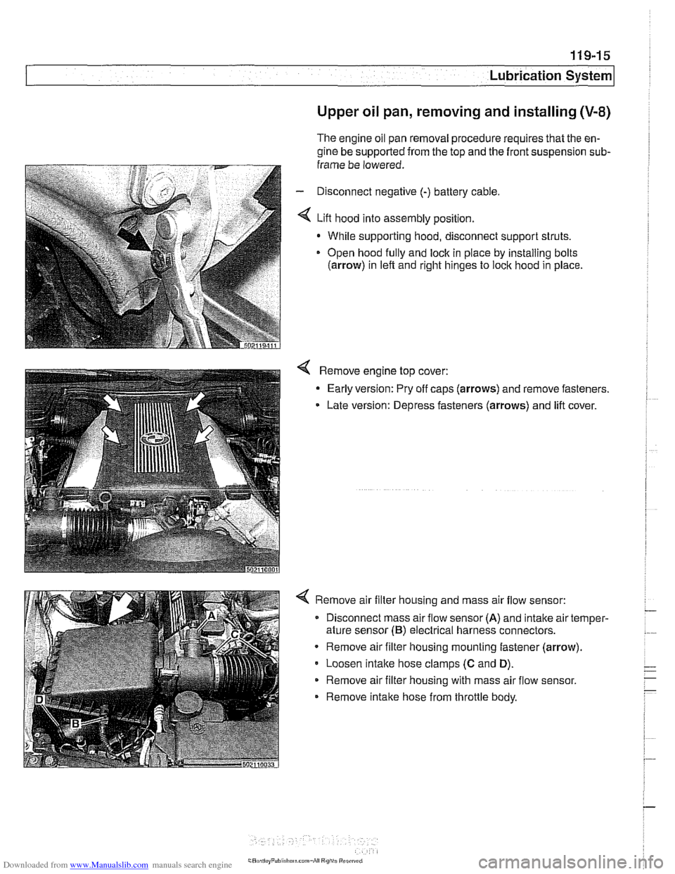
4 Lift hood into assembly position.
- While supporting hood, disconnect support struts.
Open hood
fully and lock in piace by installing bolts
(arrow) in left and right hinges to lock hood in place
4 Remove engine top cover:
- Early version: Pry off caps (arrows) and remove fasteners.
Late version: Depress fasteners (arrows) and lift cover.
4 Remove air filter housing and mass air flow sensor:
Disconnect mass air flow sensor
(A) and intake air temper-
ature sensor
(B) electrical harness connectors.
Remove air filter housing mounting fastener (arrow)
Loosen
intake hose clamps (C and D).
Remove air filter housing with mass air flow sensor.
Remove intake hose from throttle body.
Page 353 of 1002
Downloaded from www.Manualslib.com manuals search engine
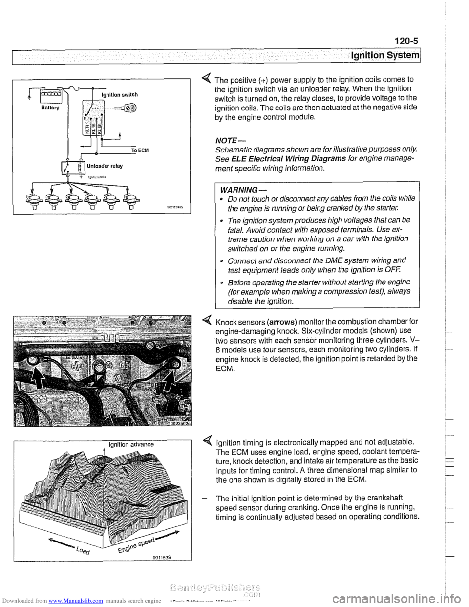
Lnition switch
4 The positive (+) power supply to the ignition coils comes to
the ignition switch via an unloader relay. When the ignition
switch is turned on, the relay closes, to provide voltage to the
ignition coils. The coils are then actuated at the negative side
by the engine control module.
NOTE-
Schematic diagrams shown are for illustrative purposes only.
See ELE Electrical Wiring Diagrams for engine manage-
ment specific wiring information.
WARNING- Do not touch or disconnect any cables from the coils while
the engine is running or being cranked by the starter:
The ignition system produces high voltages that can be
fatal. Avoid contact with exposed terminals. Use ex-
treme caution when
working on a car with the ignition
switched on or the engine running.
* Connect and disconnect the DME system wiring and
test equipment leads only when the ignition is
OFF
Before operating the starter without starting the engine
(for example when
making a compression test), always
disable the ignition.
4 Knock sensors (arrows) monitor the combustion chamber for
engine-damaging knock. Six-cylinder models (shown) use
two sensors with each sensor monitoring three cylinders.
V-
8 models use four sensors, each monitoring two cylinders. If
engine
knock is detected, the ignition point is retarded by the
ECM.
I Ignition advance Ignition timing is electronically mapped and not adjustable.
The ECM uses engine load, engine speed, coolant tempera-
ture, knock detection, and intake air temperature as the basic
inputs for timing control.
A three dimensional map similar to
the one shown is digitally stored in the ECM.
- The initial ignition point is determined by the crankshaft
speed sensor during cranking. Once the engine is running.
timing is continually adjusted based on operating conditions.
Page 363 of 1002
Downloaded from www.Manualslib.com manuals search engine
120-15
Ignition system1
Exhaust camshaft position sensor, replacing
(M52 TU and M54 engines)
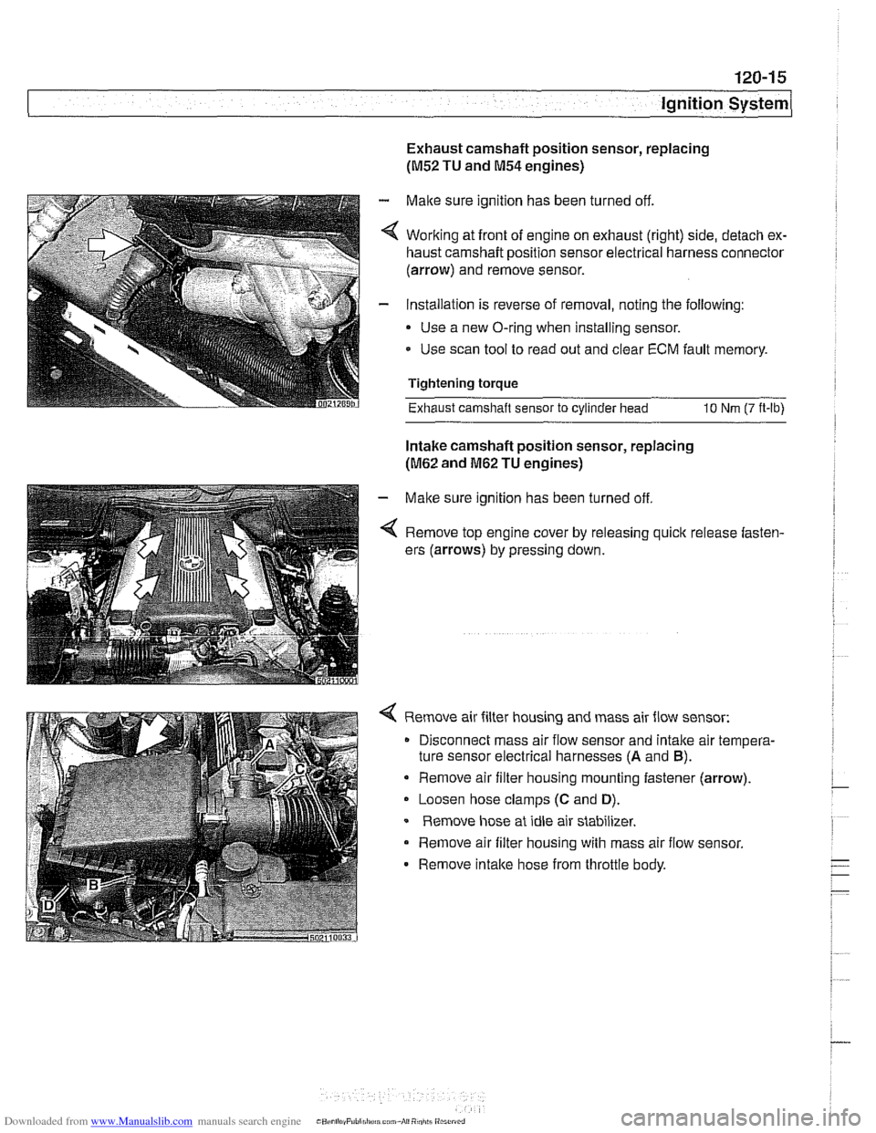
- Make sure ignition has been turned off.
4 Working at front of engine on exhaust (right) side, detach ex-
haust camshaft position sensor electrical harness connector
(arrow) and remove sensor.
- Installation is reverse of removal, noting the following:
Use a new O-ring when installing sensor.
- Use scan tool to read out and clear ECM fault memory.
Tightening torque
Exhaust camshaft sensor
to cylinder head 10 Nm (7 ft-lb)
Intake camshaft position sensor, replacing
(M62 and M62 TU engines)
- Make sure ignition has been turned off
4 Remove top engine cover by releasing quick release fasten-
ers (arrows) by pressing down.
4 Remove air filter housing and mass air flow sensor:
Disconnect mass air flow sensor and
intalte air tempera-
ture sensor electrical harnesses
(A and B).
Remove air filter housing mounting fastener (arrow).
Loosen hose clamps
(C and D).
Remove hose at idle air stabilizer.
Remove air filter housing with mass air flow sensor.
- Remove intalte hose from throttle body.
Page 379 of 1002
Downloaded from www.Manualslib.com manuals search engine
Battery, Starter, ~lternatorl
Charging system quick-check
Use a digital multimeter to measure voltage across the bat-
tery terminals with key off and then again with engine running.
Battery voltage should be about 12.6 volts with key off and be-
tween 13.5 and 14.5 volts with engine running.
NOTE-
The regulated voltage (engine running) should be between
13.2 and 14.5, depending on temperature andoperating con-
ditions.
If the voltage is higher than 14.8, the voltage regula-
tor or
mulitfunction controller is most likely faulty
Check for clean and tight battery cables. Check ground cable
running from negative
(-) battery terminal to chassis and
ground cable running from engine to chassis. Check alterna-
tor drive belt condition and tension.
Charging system, checking
CAUTIOI\C
* Do not disconnect the battery while the engine is running.
Damage to the alternator and/or engine electronic systems
may result.
Only use a digital multimeter when testing charging
system components.
--7
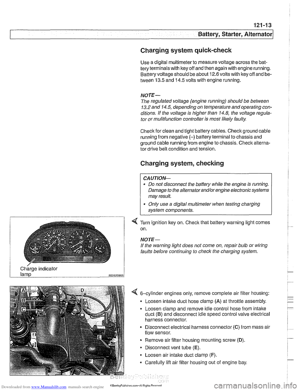
4 Turn ignition key on. Check that battery warning light comes
on.
NOTE-
If the warning light does not come on, repair bulb or wiring
faults before continuing to checlc the charging system.
/ Charge indicator
502820805
4 6-cylinder engines only, remove complete air filter housing:
Loosen
intake duct hose clamp (A) at throttle assembly.
Loosen clamp and remove idle control hose from intake
duct
(B) and disconnect idle speed control valve electrical
harness connector.
Disconnect electrical harness connector
(C) from mass air
flow sensor.
Remove air filter housing mounting screw
(D).
Disconnect vent tube (E).
Loosen air intake duct clamp (F).
Carefully lift air filter housing out of engine bay.
Page 391 of 1002
Downloaded from www.Manualslib.com manuals search engine
130-1
130 Fuel injection
General ........................... .I3 0.2
Tools and test equipment .............. .I3 0.3
Warnings and cautions ................ .I3 0.5
Fuel Supply ....................... .I3 0.6
Relieving system fuel pressure .......... .I3 0.6
Siemens MS 41 . 1. ................... 1 30-7
ECM relay. testing .................... .I3 0.7
Mass air flow (MAF) sensor.
checking and replacing
................ .I3 0.9
Engine coolant temperature (ECT) sensor.
testing and replacing
.................. 130-10
Intake air temperature (IAT) sensor.
testing and replacing
................. .I3 0.1 1
Throttle position sensor (TPS).
testing and replacing
.................. 130-1 2
ldle speed control valve.
checking and replacing
............... .I3 0.1 3
Fuel injectors. checking and replacing .... 130-15
Evaporative emissions. overview ....... .I3 0.1 6
Secondary air injection. overview ....... .I3 0-17
Engine control module (ECM).
removing and installing
................ 130-18
Siemens MS 41.1 ECM pin assignments . .I3 0.19
Siemens MS 42.0 and MS 43.0. ..... .I3 0.23
ECM relay. testing ................... .I3 0.27
Mass air flow (MAF) sensor.
checking and replacing
............... .I3 0.28
Engine coolant temperature (ECT) sensor.
testing and replacing
................. .I3 0.30
Intake air temperature (IAT) sensor.
testing and replacing
................. .I3 0.31
MS 42.0 throttle valve assembly. replacing . 130-32
MS 43.0 throttle valve assembly. replacing . 130-35
Throttle cable. adjusting (MS 42.0) ...... .I3 0.38
ldle speed control valve. checking
and replacing
....................... .I3 0.38
Evaporative emissions control diagrams . . 130- 39
Evaporative emissions control.
(MS
42.0 and MS 43.0). .............. .I3 0.39
Engine control module (ECM).
removing and installing
................ 130-40
Siemens MS 42.0 and MS 43.0
ECM pin assignments ................. 130-41
Bosch M5.2 (M62 up to 911997)
BOSC~ M5.2.1 (M62 911997 to 911998) 130-46
M5.2 system features ................. 130-47
M5.2.1 system features ............... 130-47
ECM relay. testing ................... 130-49
Oxygen sensors. checking ............. 130-51
Fuel injectors. checking and replacing .... 130-52
Mass air flow (MAF) sensor. replacing .... 130-53
ldle speed control valve. testing
and replacing
....................... 130-54
Throttle position sensor (TPS).
testing and replacing
................. 130-55
Engine coolant temperature (ECT) sensor.
testing and replacing
................. 130-55
Intake air temperature (IAT) sensor.
testing and replacing
................. 130-57
Auxiliary throttle valve (ADS) (M62 and
M62 TU engine). replacing ..... 130-57
Evaporative system pressure
leak diagnosis. overview
(5.2.1 only) ..... 130-58
Bosch 5.2 ECM pin assignments
(M62 UP to 911 997) ................... 130-59
~osch 5.2.1 ECM pin assignments
(M62 911 997 to 911 998) ............... 130-62
BOSC~ ME 7.2 ..................... 1 30-66
ME 7.2 system overview ............... 130-67
EDK adaptation ..................... 130-69
ECM relay. checking .................. 130-69
Engine coolant temperature
(ECT) sensor. testing
................. 130-71
Engine coolant temperature
(ECT) sensor. replacing
............... 130-71
Oxygen sensors. replacing ............. 130-72
Fuel injectors. removing and installing .... 130-72
Mass air flow (MAF) sensor.
removing and installing
................ 130-73
Evaporative system pressure
leak diagnosis. overview
............... 130-74
Secondary air injection. overview ........ 130-75
Bosch ME 7.2 ECM pin assignments .... 130-76
Page 399 of 1002
Downloaded from www.Manualslib.com manuals search engine
Fuel Injection I
Mass air flow (MAF) sensor,
checking and replacing
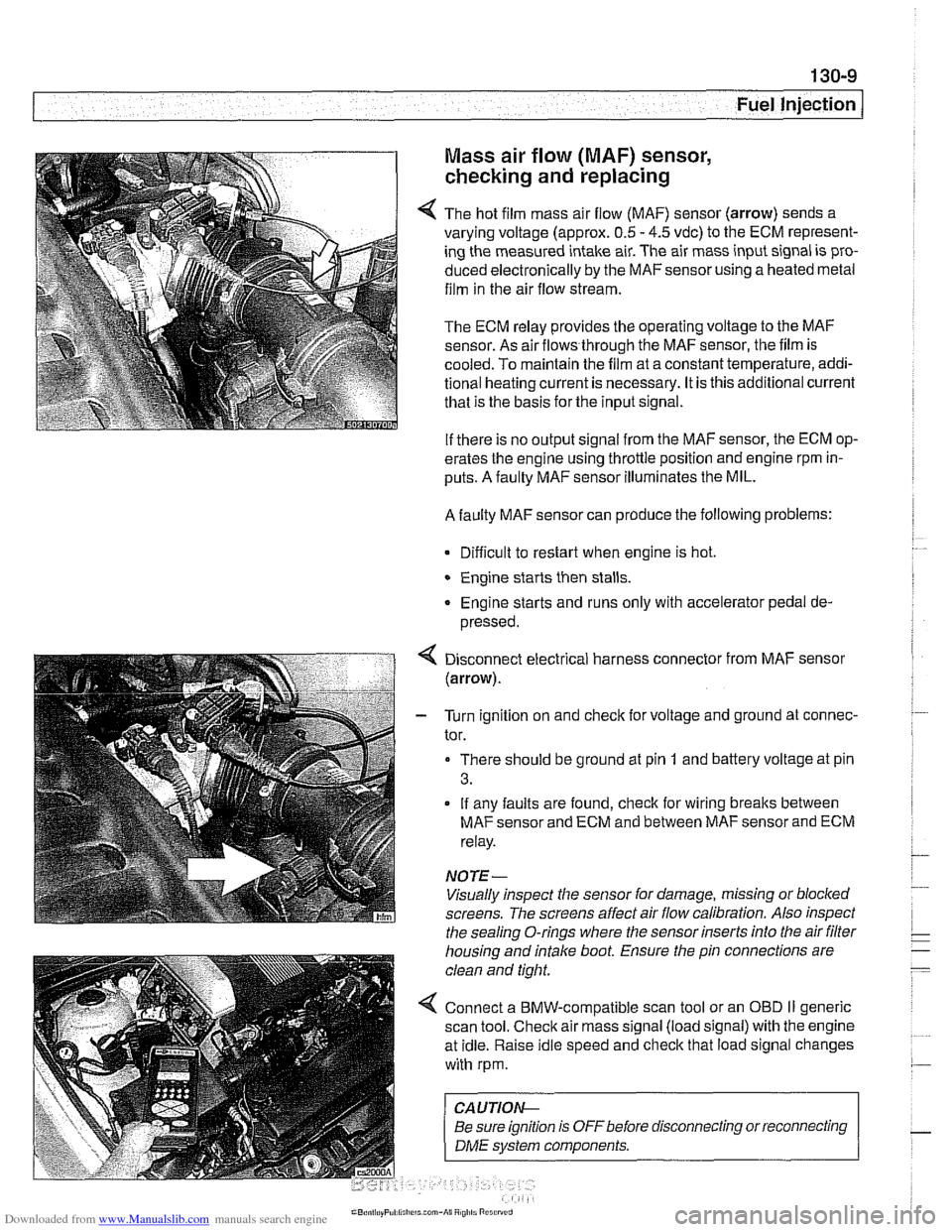
4 The hot film mass air flow (MAF) sensor (arrow) sends a
varying voltage (approx.
0.5 - 4.5 vdc) to the ECM represent-
ing the measured intake air. The air mass input signal is pro-
duced electronically by the
MAFsensorusing a heated metal
film in the air flow stream.
The ECM relay provides the operating voltage to the MAF
sensor. As air flows through the MAF sensor, the film is
-
cooled. To maintain the film at a constant temperature, addi-
tional heating current is necessary. It is this additional current
that is the basis for the input signal.
If there is no output signal from the MAF sensor, the ECM op-
erates the engine using throttle position and engine rpm in-
puts. A faulty MAF sensor illuminates the MIL.
A faulty MAF sensor can produce the following problems:
Difficult to restart when engine is hot.
Engine starts then stalls.
Engine starts and runs only with accelerator pedal de-
pressed.
Disconnect electrical harness connector from MAF sensor
(arrow).
- Turn ignition on and check for voltage and ground at connec-
tor.
There should be ground at pin
1 and battery voltage at pin
3.
If any faults are found, check for wiring breaks between
MAF sensor and ECM and between MAF sensor and ECM
relay.
NOTE-
Visually inspect the sensor for damage, missing or blocked
screens. The screens affect air flow calibration. Also inspect
the sealing O-rings where the sensor inserts into the air
filter
housing and intake boot. Ensure the pin connections are
clean and tight.
4 Connect a BMW-compatible scan tool or an OBD II generic
scan tool. Check air mass signal (load signal) with the engine
at idle. Raise idle speed and check that load signal changes
with rpm.
CA UTIOI\C
Be sure ignition is OFFbefore disconnecting or reconnecting r
1 DME svstem components. 1
Page 400 of 1002
Downloaded from www.Manualslib.com manuals search engine
130-1 0
Fuel Injection
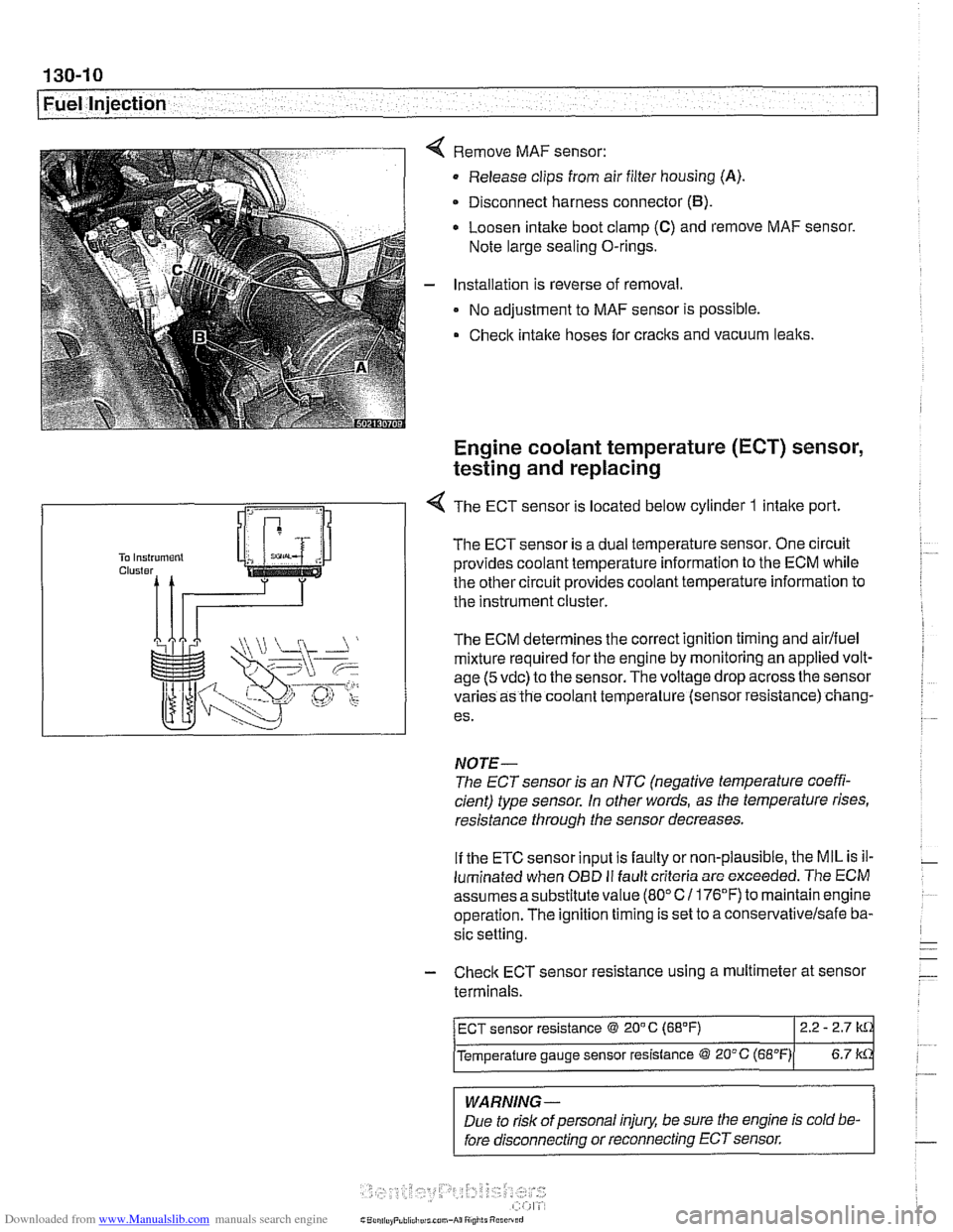
Remove MAF sensor:
Release clips from air filter housing
(A).
Disconnect harness connector (B).
Loosen intake boot clamp (C) and remove MAF sensor.
Note large sealing O-rings.
Installation is reverse of removal.
No adjustment to MAF sensor is possible.
Check intake hoses for cracks and vacuum leaks.
Engine coolant temperature (ECT) sensor,
testing and replacing
R
1 -4 The ECT sensor is located below cylinder 1 intake port
The ECT sensor is a dual temperature sensor. One circuit
provides coolant temperature information to the ECM while
the other circuit provides coolant temperature information to
the instrument cluster.
The ECM determines the correct ignition timing and
airlfuel
mixture required for the engine by monitoring an applied volt-
age
(5 vdc) to the sensor. The voltage drop across the sensor
varies as the coolant temperature (sensor resistance) chang-
es.
NOTE-
The ECT sensor is an NTC (negative temperature coeffi-
cient) type sensor. in other words, as the temperature rises,
resistance through the sensor decreases.
If the ETC sensor input is faulty or non-plausible, the MIL is il-
luminated when
OED II fault criteria are exceeded. The ECM
assumes asubstitute value
(80°C1 176°F) to maintainengine
operation. The ignition timing is set to a
conse~ativelsafe ba-
sic setting.
- Check ECT sensor resistance using a multimeter at sensor
terminals.
-
WARNING -
Due to risk of personal injury, be sure the engine is cold be-
fore disconnecting or reconnecting ECT sensor.
ECT sensor resistance @ 20" C (68°F) 2.2 - 2.7
Temperature gauge sensor resistance @ 20°C (~B"F)( 6.7 k