Fuel injector BMW 528i 1999 E39 Owner's Manual
[x] Cancel search | Manufacturer: BMW, Model Year: 1999, Model line: 528i, Model: BMW 528i 1999 E39Pages: 1002
Page 406 of 1002
Downloaded from www.Manualslib.com manuals search engine
I Fuel Injection
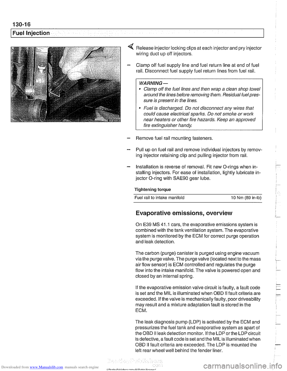
Release injector locking clips at each injector and pry injector
wiring duct up off injectors.
Clamp off fuel supply line and fuel return line at end of fuel
rail. Disconnect fuel supply fuel return lines from fuel rail.
WARNING -
Clamp off the fuel lines and then wrap a clean shop towel
around the lines before removing them. Residual
fuelpres-
sure is present in the lines.
Fuel is discharged. Do not disconnect any wires that
could cause electrical
sparks. Do not smoke or work
near heaters or other fire hazards. Keep an approved
I fire extinguisher handy. I
- Remove fuel rail mounting fasteners
- Pull up on fuel rail and remove individual injectors by remov-
ing injector retaining clip and pulling injector from rail.
- Installation is reverse of removal. Fit new O-rings when in-
stalling injectors. For ease of installation, lightly lubricate in-
jector O-ring with
SAE9O gear lube.
Tightening torque Fuel rail to
intake manifold 10 Nm (89 in-lb)
Evaporative emissions, overview
On E39 MS 41 .I cars, the evaporative emissions system is
combined with the tank ventilation system. The evaporative
system is monitored by the ECM for correct purge operation
and leak detection.
The carbon (purge) canister is purged using engine vacuum
via the
purgevalve.The purgevalve (located nextto the mass
airflow sensor) is ECM controlled and regulates the purge
flow into the intake manifold. The valve is powered open and
closed by an internal spring.
If the evaporative emission valve circuit is faulty, a fault code
is set and the MIL is illuminated when OBD
II fault criteria are
exceeded. If the valve is mechanically faulty, poor driveability
may result and a mixture adaptation fault is stored in the
ECM.
The leak diagnosis pump (LDP) is activated by the ECM and
pressurizes the fuel tank and evaporative system as apart of
theOED I1 leakdetection monitor. If the LDP orthe LDP circuit
is defective, afault code is set and the MIL is illuminated when
OBD
I1 fault criteria are exceeded. The LDP is mounted the
left rear wheel well behind the fender liner.
Page 408 of 1002
Downloaded from www.Manualslib.com manuals search engine
130-1 8
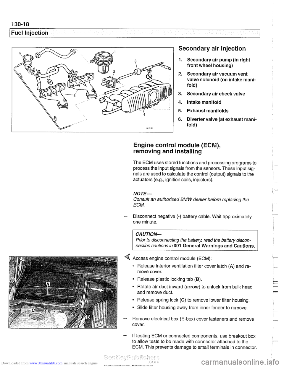
1 Fuel injection Secondary air injection
1. Secondary air pump (in right
front wheel housing)
2. Secondary air vacuum vent
valve solenoid (on intake mani-
fold)
3. Secondary air check valve
4. Intake manifold
5. Exhaust manifolds
6. Diverter valve (at exhaust mani-
fold)
Engine control module (ECM),
removing and installing
The ECM uses stored functions and processing programs to
process the input signals from the sensors. These input sig-
nals are used to calculate the control (output) signals to the
actuators
(e.g., ignition coils, injectors).
NOTE-
Consult an authorized BMW dealer before replacing the
ECM.
- Disconnect negative (-) battery cable. Wait approximately
one minute.
Prior to disconnecting the
battely, read the battery discon-
nection cautions in
001 General Warnings and Cautions.
Access engine control module (ECM):
Release interior ventilation filter cover latch
(A) and re-
move cover.
Release plastic locking tab
(B).
Rotate air duct inward (arrow) to unloclc from bulk head
and remove duct.
Release spring lock
(C) to remove lower filter housing.
Slide filter housing away from inner fender to remove.
- Remove electrical box (E-box) cover fasteners and remove
cover.
- If testing ECM or connected components, use breakout box
to allow tests to be made with connector attached to the
ECM. This prevents damage to small terminals in connector.
Page 410 of 1002
Downloaded from www.Manualslib.com manuals search engine
I Fuel Injection
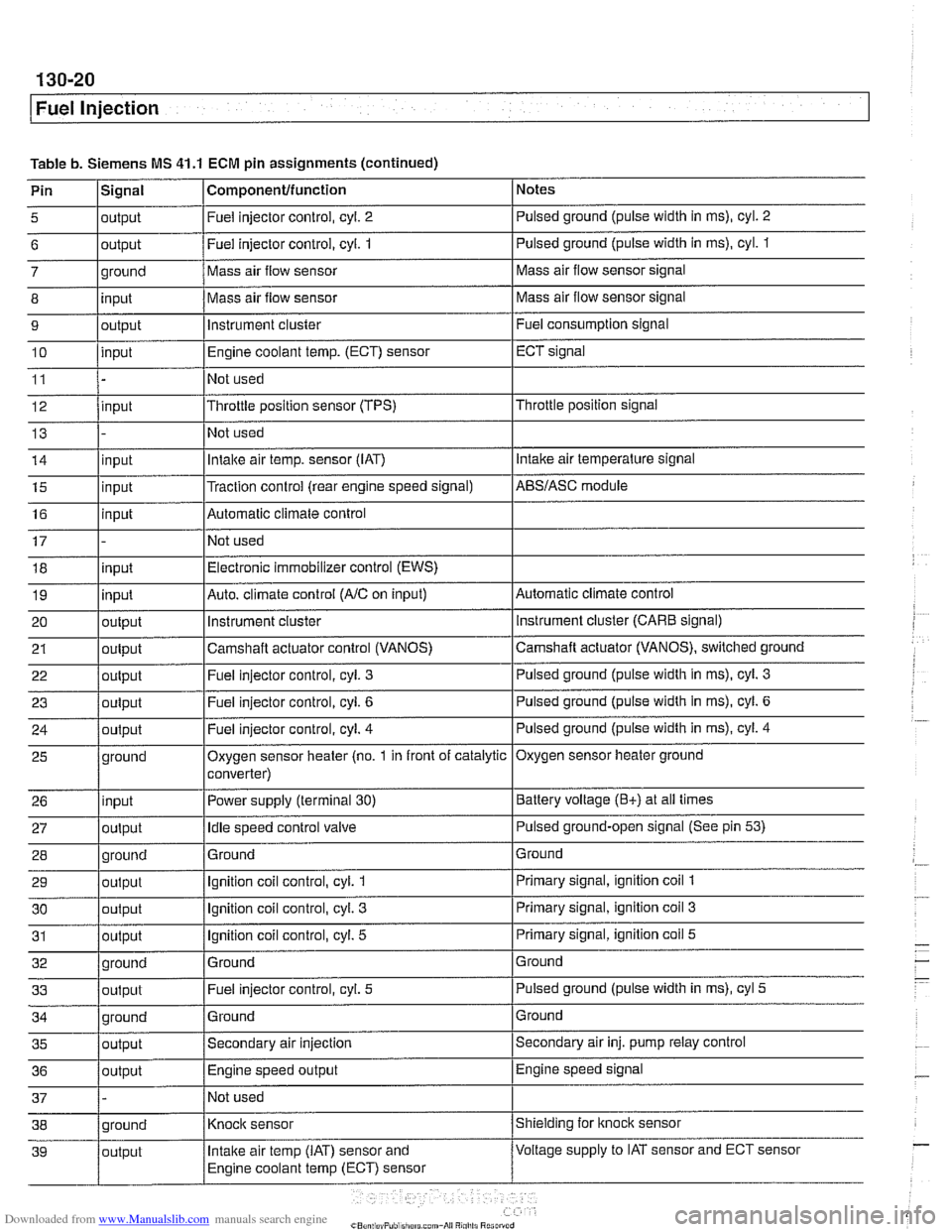
Table b. Siemens MS 41.1 ECM pin assignments (continued)
Pin
l~iqnal I Componentlfunction 1 Notes I - I I
5 loutput I Fuel injector control, cyl. 2 I Pulsed ground (pulse width in ms), cyl. 2 I I I
6 loutput /Fuel injector control, cyi. 1 I Pulsed ground (pulse width in ms), cyl. 1
I I I
14 linput I Intake air temp. sensor (IAT) I Intake air temperature signal
- 7
8
9
10
11
12
13
ground
input
output
input
input
15
16
17 18
19
20
21
22
I - I I
35 loutput /Secondary air injection ISecondary air inj. pump relay control
25
26
27
28
29
30
31
32
33
36
/output I Engine speed output IEngine speed signal
Mass air flow sensor
Mass air flow sensor
instrument cluster
Engine coolant
temp.
(ECT) sensor
Not used
Throttle position sensor (TPS)
Not used
input
input
input
input
output
output
out~ut
37 1 - /Not used I
Mass air flow sensor signal
Mass air flow sensor signal
Fuel consumption signal
ECT signal
Throttle position signal
ground
input
output
ground
output
output
output
ground
output
Traction control (rear engine speed signal) Automatic climate control
Not used Electronic immobilizer control (EWS)
Auto. climate control
(AIC on input)
instrument
cluster
Camshaft actuator control (VANOS)
Fuel iniector control, cvl.
3
AES/ASC module
Automatic climate control instrument cluster (CARE signal)
Camshaft actuator (VANOS), switched ground
Pulsed ground (pulse width in
ms), cyl. 3
Oxygen sensor heater (no. 1 in front of catalytic
converter)
Power supply (terminal
30)
Idle speed control valve
Ground
Ignition coil control, cyl.
1
Ignition coil control, cyl. 3
Ignition coil control, cyl. 5
Ground Fuel injector control, cyl.
5
Oxygen sensor heater ground
Battery voltage
(E+) at all times
Pulsed ground-open signal (See pin
53)
Ground
Primary signal, ignition coil
1
Primary signal, ignition coil 3
Primary signal, ignition coil 5
Ground
Pulsed ground (pulse width in ms), cyl
5
Page 430 of 1002
Downloaded from www.Manualslib.com manuals search engine
130-40
Fuel Injection
Engine control module (ECM),
removing and installing
The ECM uses stored functions and processing programs to
process the input signals from the sensors. These input sig-
nals are used to calculate the control (output) signals to the
actuators
(e.g., ignition coils, injectors).
NOTE-
Consult an authorized BMW dealer before replacing the
ECM.
- Disconnect negative (-) battery cable. Wait approximately
one minute.
CAUTION-
Prior to disconnecting the batteg read the battery discon-
nection cautions
in 001 General Warnings and Cautions.
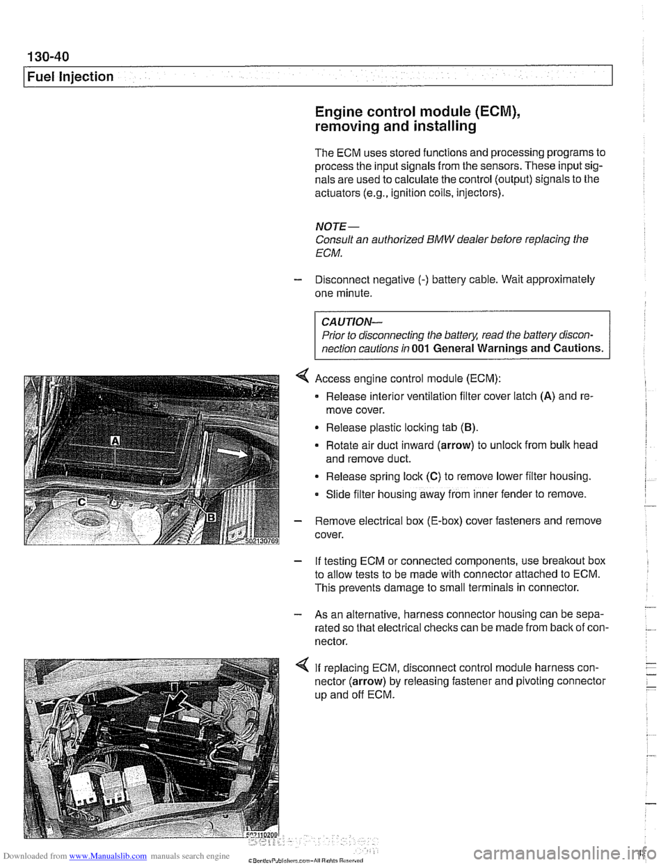
4 Access engine control module (ECM):
Release
interlor ventilation filter cover latch (A) and re-
move cover.
Release plastic loclting tab
(B).
Rotate air duct inward (arrow) to unloclt from bulk head
and remove duct.
Release spring lock
(C) to remove lower filter housing.
Slide
f~lter hous~ng away from inner fender to remove.
- Remove electrical box (E-box) cover fasteners and remove
cover.
- If testing ECM or connected components, use breakout box
to allow tests to be made with connector attached to ECM.
This prevents damage to small terminals in connector.
- - As an alternative, harness connector housing can be sepa-
rated so that electrical checks can be made from
back of con-
nector.
4 If replacing ECM, disconnect control module harness con-
nector (arrow) by releasing fastener and pivoting connector
up and off ECM.
Page 433 of 1002
![BMW 528i 1999 E39 Owners Manual Downloaded from www.Manualslib.com manuals search engine
130-43
Fuel Injection ]
I I I
12 llnput IFeedback signal, engine start /Starter
Table c. Siemens MS 42.0 and MS 43.0 ECM pin assignments BMW 528i 1999 E39 Owners Manual Downloaded from www.Manualslib.com manuals search engine
130-43
Fuel Injection ]
I I I
12 llnput IFeedback signal, engine start /Starter
Table c. Siemens MS 42.0 and MS 43.0 ECM pin assignments](/img/1/2822/w960_2822-432.png)
Downloaded from www.Manualslib.com manuals search engine
130-43
Fuel Injection ]
I I I
12 llnput IFeedback signal, engine start /Starter
Table c. Siemens MS 42.0 and MS 43.0 ECM pin assignments (continued)
I I - I
13 Input /I Alternator (generator) Notes
Throttle
valve
Crankshaft position sensor
Throttle valve (MS
42.0)
Throttle valve
Pin
6
7
8
9
10
11
14
15
16
17
18
19
20
I 1- I
23 l~round I~round, intaite air temperature sensor /Intake air temperature sensor
Signal
Output
Input
Input
Input
I I I
Component/function
Not used
Throttle valve supply potentiometer
2
Signal, crankshaft position sensor
Signal,
pedal position sensor 2 (MS 42.0)
Signal, throttle position sensor 1
Not used
Ground
Ground
Input
Ground
Ground
Input
Ground Cranltshaft position sensor
21
24
25
26
27
28
29
30
I 1- I
33 1 input ISignal, cylinder 1 fuel injector /cylinder 1 fuel injector
Ground, throttle position sensor (MS
42.0)
Ground, exhaust camshaftsensor I
Signal, pedal position sensor 1 (MS 42.0)
Ground, mass air flow sensor
Ground, intake camshaft sensor
1
Signal, throttle potentiometer 1
Ground, throttle position sensor
22 loutput I~ignal, intake air temperature Ilntake air temperature sensor
I I - I
Throttle
valve (MS 42.0)
Camshaft position sensor I
Throttle valve (MS
42.0)
Hot film mass air flow sensor
Camshaft position sensor i
Throttle valve
Throttle valve
Ground
Output
Ground Input
Output
Ground
Output
Out~ut
Ground, crankshaft position sensor
Knoclt sensor
31
34
35
36
37
38
39
Signal, coolant temperature sensor
Ground, coolant temperature sensor
Signal,
oil pressure
Signal, engine
oil temperature sensor
Ground, engine oil temperature sensor
Signal, knock sensor
Signal, knock sensor
32 loutput ISignal, ltnock sensor l~nock sensor
40
41
Coolant temperature sensor
Coolant temperature sensor
Oil pressure switch
Oil temperature sensor
Oil temperature sensor
Knoclt sensor
I
Input
input
Input
Input
Input
Inout
Signal, knock sensor
Input
Input Signal, cylinder
2 fuel injector
Signal, cylinder
3 fuel injector
Signal, cylinder
4 fuel injector
Signal, cylinder
5 fuel injector
Signal, cylinder
6 fuel injector
Sianai, oil level sensor Cylinder
2 fuel
injector
Cylinder
3 fuel injector
Cylinder
4 fuel injector
Cylinder
5 fuel injector
Cylinder
6 fuel injector
Oil level sensor
-
Signal. VANOS inlet valve
Signal. VANOS outlet valve VANOS
inlet valve
VANOS outlet valve
Page 442 of 1002
Downloaded from www.Manualslib.com manuals search engine
.. .-
/Fuel lnjeciion
NOJE-
With engine oft disconnect harness connector and checlc
heating element resistance between white wires on the sen-
sor side of harness. If the element is electrically open (no
continuity), replace sensor.
- If oxygen sensor does not produce a fluctuating voltage and
preheater circuit is
OK, replace sensor.
NOJE-
If not already applied, coat oxygen sensor threads w~th anti-
seize compound before installat~on. Do not get the com-
pound on the sensor tip.
Tightening torque Oxygen sensor to exhaust system
55 Nm (41 ft-lb)
Fuel injectors, checking and replacing
The fuel iniectors are switched on and off (oaened and
closed)
by'the ECM. The injectors are connkcted to acom-
mon power source. A ground signal from the ECM is used to
open and close the injectors.
CA U JIOG
Use only a digital multimeter or an LED injector tester when
testing injectors or wiring. Use of an analog
VOM or incan-
descent test light may damaqe the engine controlmodule.
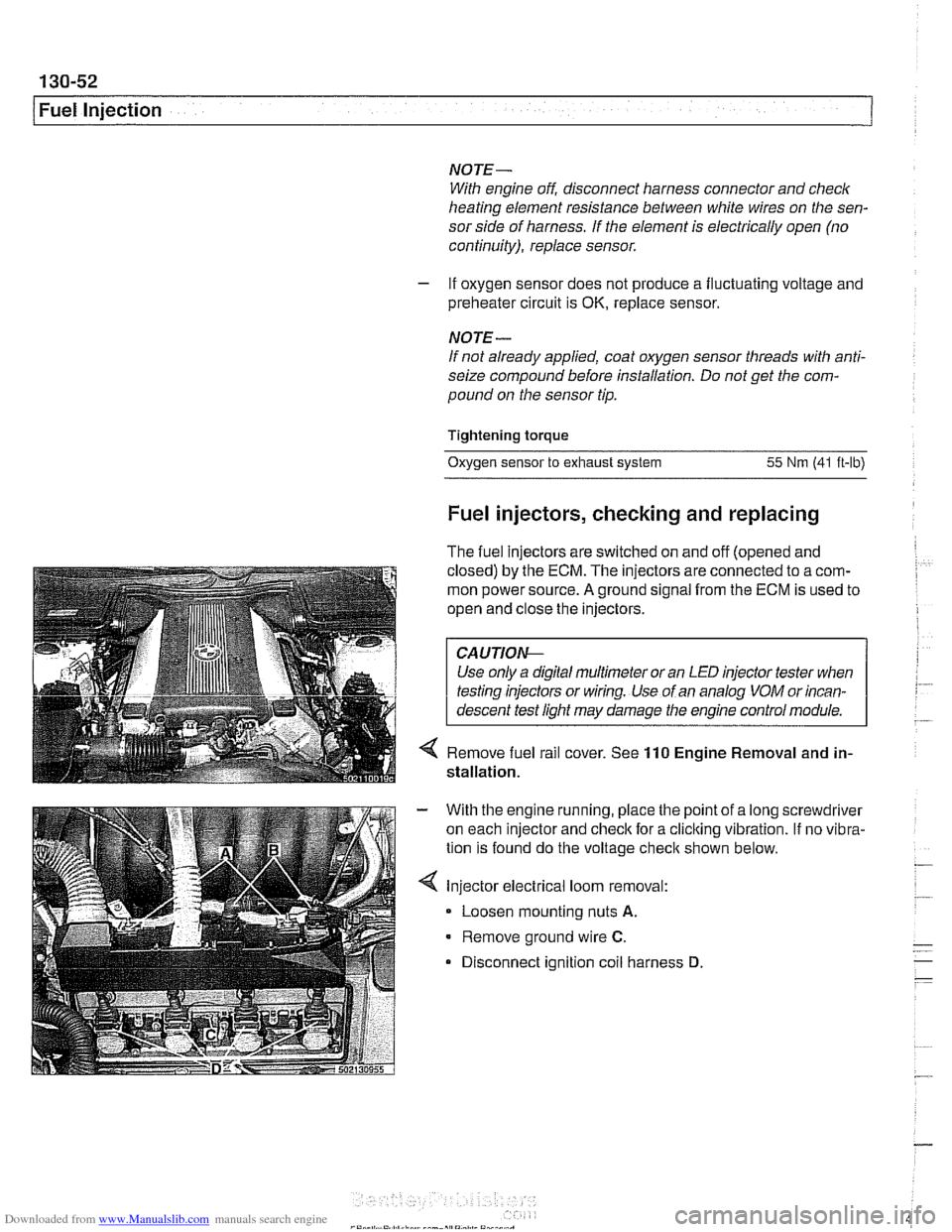
4 Remove fuel rail cover. See 110 Engine Removal and in-
stallation.
With the engine running, place the point of a long screwdriver
on each injector and check for a cliclting vibration.
If no vibra-
tion is found do the voltage
checit shown below.
Injector electrical loom removal:
- Loosen mounting nuts A.
Remove ground wire C.
Disconnect ignition coil harness D
Page 443 of 1002
Downloaded from www.Manualslib.com manuals search engine
Fuel Injection I
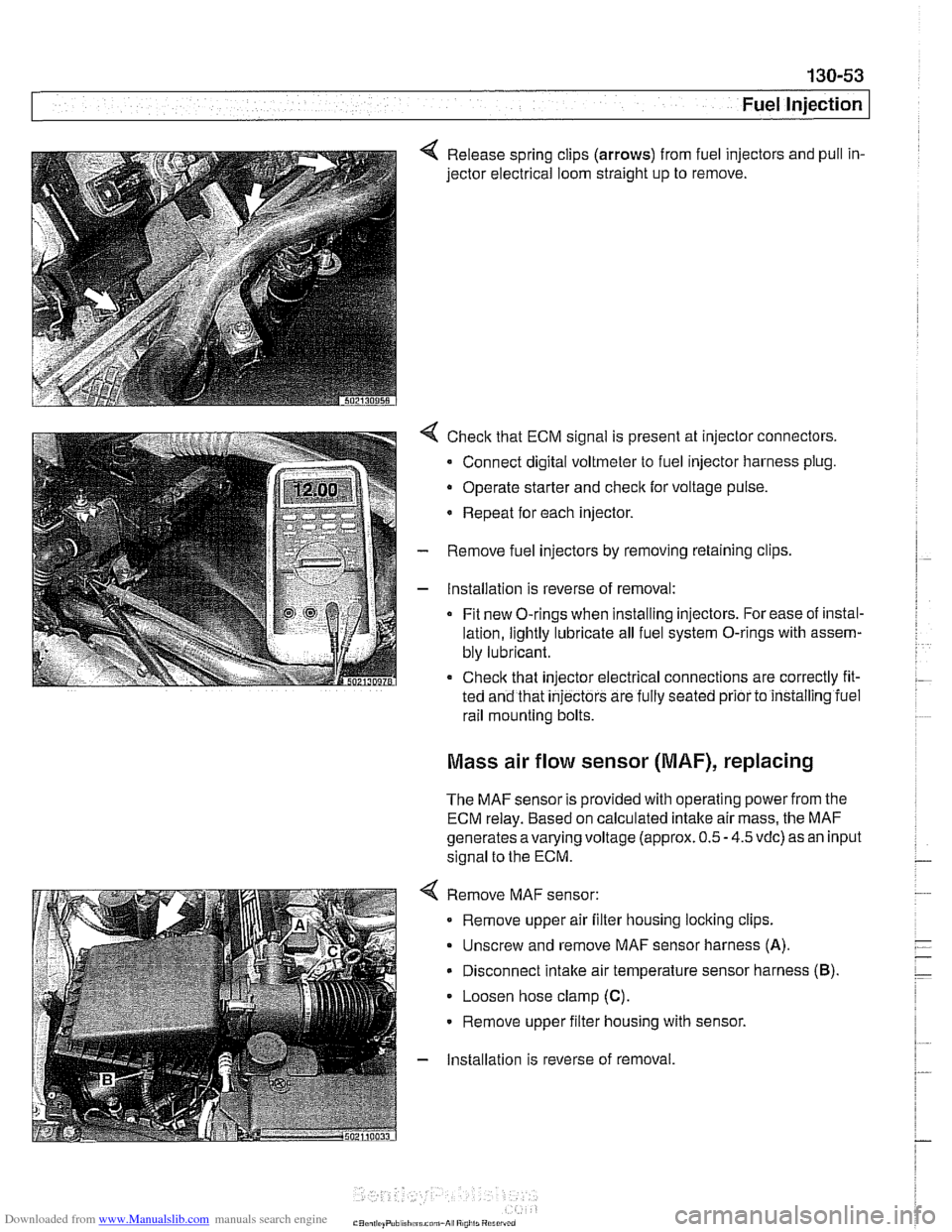
4 Release spring clips (arrows) from fuel injectors and pull in-
jector electrical loom straight up to remove.
4 Check that ECM signal is present at injector connectors.
- Connect digital voltmeter to fuel injector harness plug.
Operate starter and
check for voltage pulse.
* Repeat for each injector.
- Remove fuel injectors by removing retaining clips
- Installation is reverse of removal:
Fit new O-rings when installing injectors. For ease of instal-
lation, lightly lubricate all fuel system O-rings with assem-
bly lubricant.
Check that injector electrical connections are correctly fit-
ted and that
injectors are fully seated prior to installing iuel
rail mounting bolts.
Mass air flow sensor (MAF), replacing
The MAF sensor is provided with operating power from the
ECM relay. Based on calculated intake air mass, the MAF
generates
avarying voltage (approx. 0.5 - 4.5 vdc) as an input
signal to the ECM.
4 Remove MAF sensor:
Remove upper air filter housing locking clips.
Unscrew and remove MAF sensor harness
(A).
Disconnect intake air temperature sensor harness (B).
Loosen hose clamp (C).
Remove upper filter housing with sensor.
- Installation is reverse of removal
Page 454 of 1002
Downloaded from www.Manualslib.com manuals search engine
-
Fuel Injection
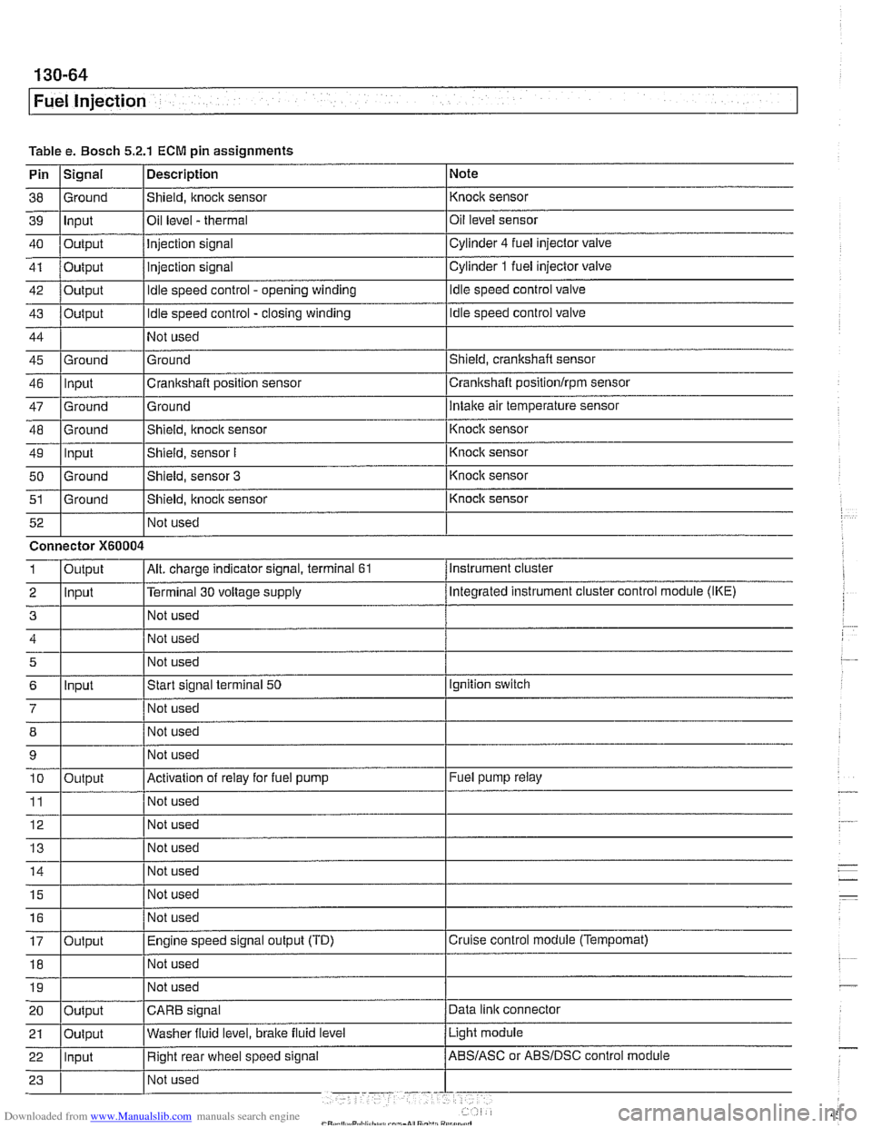
Table e. Bosch 5.2.1 ECM pin assignments
Pin
I~iqnal 1 Description 1 Note
I I I
46 llnput ICrankshaft position sensor Icrankshaft positionlrpm sensor
38
39
40
41
42
43
44
45 Ground Input
Output
Output
Output
Output
Ground
47
48
49
50
51
Not used
I Not used
52
Shield, knock sensor
Oil level
- thermal
Injection signal
injection signal
Idle speed control - opening winding
Idle speed control - closing winding
Not used
Ground
Ground
-- Ground Input
Ground
Ground Not used Knock sensor
Oil level sensor
Cylinder
4 fuel injector
valve
Cylinder
1 fuel injector valve
Idle speed control valve
Idle speed control valve
Shield, crankshaft sensor
5
6
7
12 Not used
Ground
Intake air temperature sensor
Connector
X60004
8
9 10
11
14 1 1 Not used I
Shield, knock sensor
Shield, sensor
I
Shield, sensor 3
Shield, itnock sensor
Input
- Knoclc sensor
Knock sensor
Knock sensor
Knock sensor
Instrument cluster
Output
2 llnput l~erminal 30 voltage supply /Megrated instrument cluster control module (IKE)
Alt. charge indicator signal, terminal 61 1
Not used
Start signal terminal
50
Not used
15
16
17
18
Output
Ignition switch
Not used
Not used
Activation of relay for fuel pump
Not used
19
Fuel pump relay
Output Not used
I I I 20 loutput ICARB signal /Data link connector
Not
used
Not used
Engine speed signal output (TD)
Not used
Light module
21
Cruise control module (Tempomat)
22 llnput I Right rear wheel speed signal /ABS/ASC or ABSIDSC control module
Oulput
Washer
fluid level,
brake fluid level
Page 462 of 1002
Downloaded from www.Manualslib.com manuals search engine
130-72
Fuel Injection
I Oxygen sensors, replacing
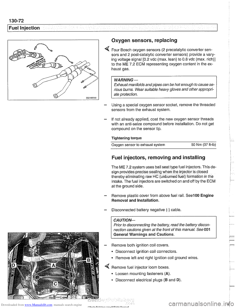
4 Four Bosch oxygen sensors (2 precatalytic converter sen-
sors and
2 post-catalytic converter sensors) provide a vary-
ing voltage signal
[0.2 vdc (max. lean) to 0.8 vdc (max. rich)]
to the ME
7.2 ECM representing oxygen content in the ex-
haust gas.
WARNING-
Exhaust manifolds and pipes can be hot enough to cause se-
rious burns. Wear suitable heavy gloves and other appropri-
ate protection.
- Using a special oxygen sensor socltet, remove the threaded
sensors from the exhaust system.
- If not already applied, coat the new oxygen sensor threads
with an anti-seize compound before installation. Do not get
compound on the sensor tip.
Tightening torque
Oxygen sensor to exhaust system
50 Nm (37 ft-lb)
Fuel injectors, removing and installing
The ME 7.2 system uses ball seat type fuel injectors. This de-
sign
prov:des precise seal'ng when the iniector is closed
therebv eiminalinq raw HC (unb~rned fue ) formalion in tne
intake.-~he fuel inkctors areswitched on and off by the ECM
at the ground side.
- Remove plastic cover from above fuel rail. See100 Engine
Removal and Installation.
- Disconnected battery negative (-) cable.
CAUTION-
Prior to disconnecting the battea read the battery discon-
nection cautions given at the front of this manual. See 001
General Warnings and Cautions.
- Remove both ignition coil covers.
Disconnect ignition coil connectors.
Remove left and right ignition coil ground wires,
4 Remove fuel injector loom boxes.
Loosen mounting fasteners
(A).
Disconnect electrical plugs (B and D).
Page 463 of 1002
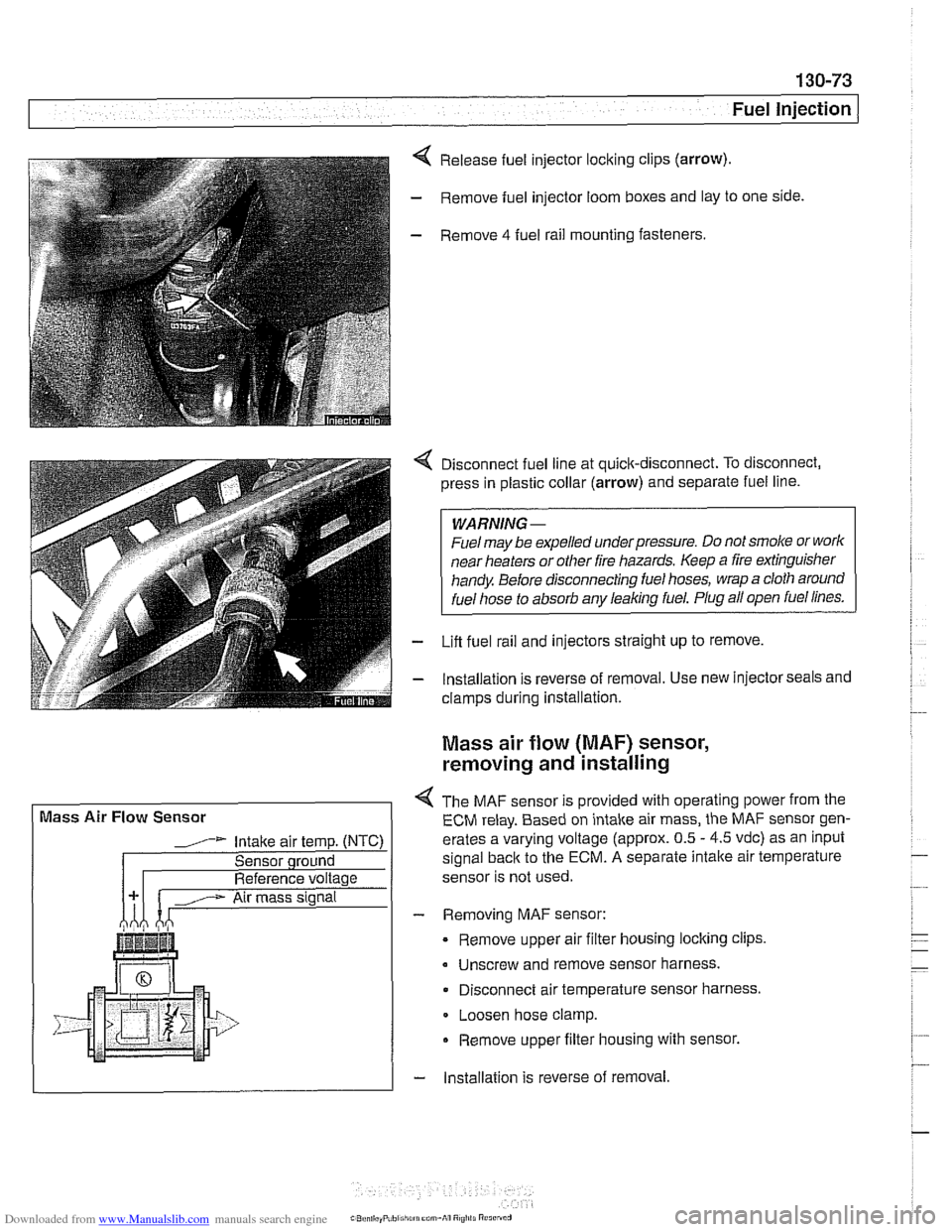
Downloaded from www.Manualslib.com manuals search engine
( Mass Air Flow Sensor
1" Intake air temp. (NTC)
Sensor qround
Reference voltage . . . -., f fitr mass signal I
Fuel Injection I
Release fuel injector locking clips (arrow).
- Remove fuel injector loom boxes and lay to one side.
- Remove 4 fuel rail mounting fasteners.
4 Disconnect fuel line at quick-disconnect. To disconnect,
press in plastic collar (arrow) and separate fuel line.
WARNING -
Fuel may be expelled underpressure. Do not srnol(e or work
near heaters or
other fire hazards. Keep a fire extinguisher
handy. Before disconnecting fuel hoses, wrap a cloth around
fuel hose
to absorb anv leakinq fuel. Plug all open fuel lines.
- Lifl fuel rail and injectors straight up to remove.
- lnstallation is reverse of removal. Use new injector seals and
clamps during installation.
Mass air flow (MAF) sensor,
removing and installing
4 The MAF sensor is provided with operating power from the
ECM relay. Based on intake air mass, the MAF sensor gen-
erates a varying voltage (approx. 0.5
- 4.5 vdc) as an input
signal
back to the ECM. A separate intalte air temperature
sensor is not used.
- Removing MAF sensor:
Remove upper air filter housing locking clips
Unscrew and remove sensor harness.
Disconnect air temperature sensor harness.
Loosen hose clamp.
Remove upper filter housing with sensor.
- lnstallation is reverse of removal