Fuel injector BMW 528i 1999 E39 Owner's Guide
[x] Cancel search | Manufacturer: BMW, Model Year: 1999, Model line: 528i, Model: BMW 528i 1999 E39Pages: 1002
Page 467 of 1002
Downloaded from www.Manualslib.com manuals search engine
Fuel lnjection
I 1- I
4 /output l~em~erature signal. E-box fan I E-box fan
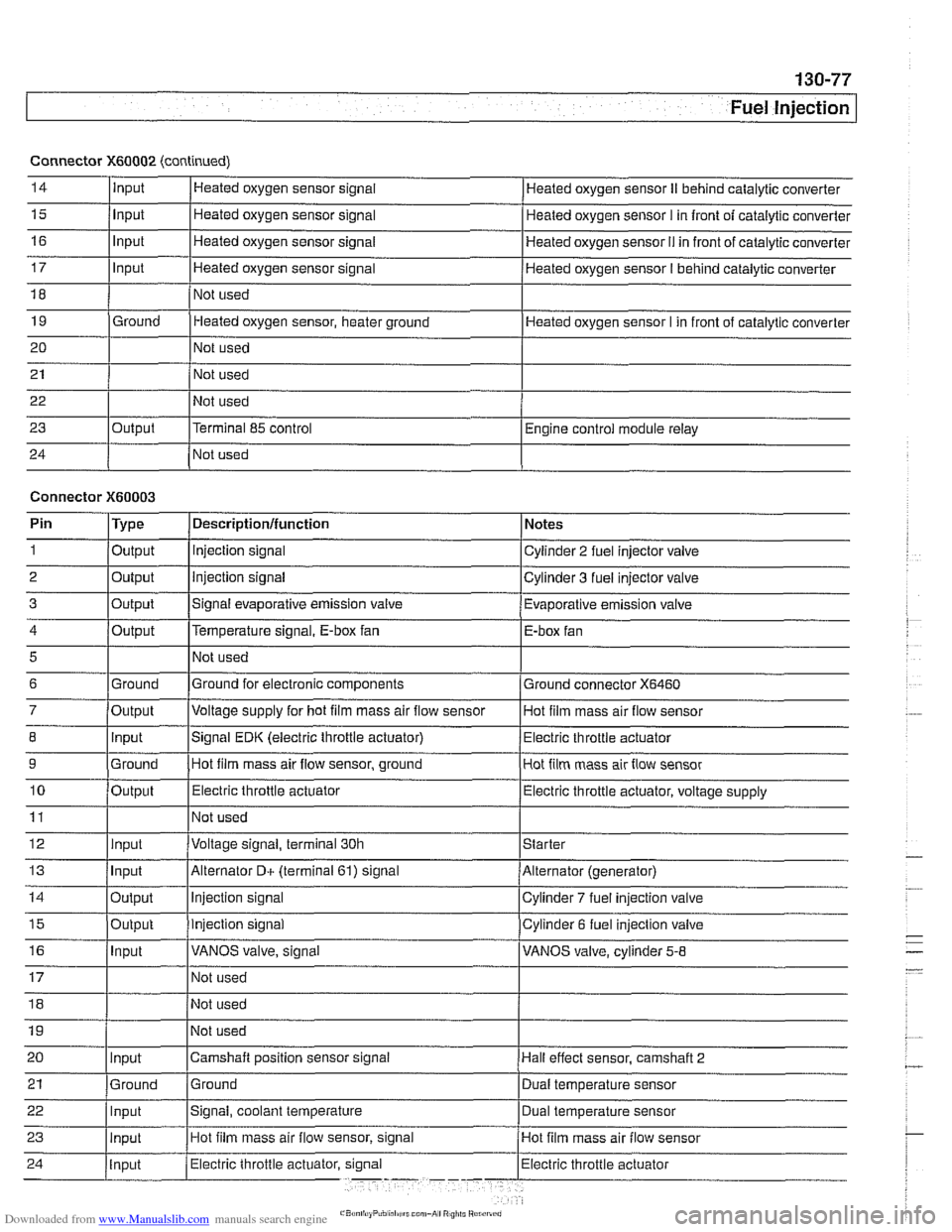
Connector
X60002 (continued)
14
15
16
17
18
19
20
21
22
23
24
5
6
7
8
9
10
11
12
13
14
15
16
Input
Input
Input
Input
Ground
Output Heated
oxygen sensor signal
Heated oxygen sensor signal
Heated oxygen sensor signal
Heated oxygen sensor signal
Not used
Heated oxygen sensor, heater ground
Not used
Not used
Not used
Terminal 85 control
Not used Heated oxygen sensor
II behind catalytic converter
Heated oxygen sensor
I in front of catalytic converter
Heated oxygen sensor
I1 in front of catalytic converter
Heated oxygen sensor
I behind catalytic converter
Heated oxygen sensor I in front of catalytic converter
Engine control module relay
Connector
X60003
Ground
Output Input
Ground
Output
Input
Input
Output
Output
Input
Pin 1
2
3
Not used
Ground for electronic components
Voltage supply for hot
film mass air flow sensor
Signal EDK (electric throttle actuator) Hot film mass air flow sensor, ground
Electric throttle actuator
Not used
Voltage signal, terminal 30h
Alternator
D+ (terminal 61) signal
Injection signal
Injection signal
VANOS valve, signal
Type
Output
Output
Output
Ground connector
X6460
Hot film mass air flow sensor
Electric throttle actuator
Hot film mass air flow sensor
Electric throttle actuator, voltage supply
Starter
Alternator (generator)
Cylinder
7 fuel injection valve
Cylinder 6 fuel injection valve
VANOS valve, cylinder
5-8
Descriptionlfunction
Injection signal
Injection signal
Signal evaporative emission valve Notes
Cylinder 2 fuel injector valve
Cylinder 3 fuel injector valve
Evaporative emission valve
Page 473 of 1002
Downloaded from www.Manualslib.com manuals search engine
Fuel Tank and Fuel Pump
Fuel pump
The electric fuel pump is mounted in the fuel tank in tandem
with the right side fuel level sender. The fuel pump delivers
pressurized fuel to the fuel injection system.
A pressure regu-
lator maintains system pressure. The quantity of fuel supplied
exceeds demand, so excess fuel returns to the fuel tank via a
return line. See
130 Fuel Injection for more information.
NOTE-
Fuel pump removal procedures are given under Fuel level
sender (right side) and fuel pump, removing and install-
ing.
Fuel tank evaporative control system
Evaporative control, also referred to as running losses con-
trol, is designed to prevent fuel system evaporative losses
from venting into the atmosphere.
The components of this system allow control and monitoring
of evaporative losses by the on-board diagnostic
(OED II)
software incorporated into the engine control module (ECM).
NOTE-
1997 V-8 models (540i) with Bosch DME M5.2 are not
equipped with an
OBD I1 running losses monitoring system.
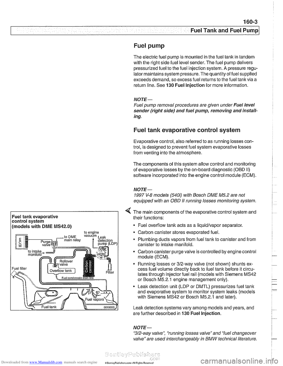
Fuel tank evaporative
control system
(models with
DME MS42.0)
4 The main components of the evaporative control system and
their functions:
Fuel overflow
tank acts as a liquidlvapor separator
Carbon canister stores evaporated fuel.
Plumbing ducts vapors from fuel tank to canister and from
canister to intake
manifold.
- Carbon canister purge valve is controlled by enginecontrol
module (ECM).
Running losses or 312-way valve (not shown) shunts ex-
cess fuel volume directly
back to fuel tank before it circu-
lates through injector fuel rail (models with Siemens MS42
or Bosch M5.2.1 engine management only).
Leak detection unit (LDP or DMTL) pressurizes fuel
tank
and evaporative system to monitor system leaks (models
with Siemens MS42 or Bosch M5.2.1 and later).
Leak detection systems vary among models and years, and
are further described in
130 Fuel Injection.
NOTE -
"3/2-way valve", 'tunning losses valve" and "fuel changeover
valve" are used interchangeably
in BMW technical literature.
Page 482 of 1002
Downloaded from www.Manualslib.com manuals search engine
Fuel Tank and Fuel Pump
Fuel delivery,
testing
Checitino fuel delive~ is a fundamental oart of troubleshoot- .. ing and diagnosing thk DME system. ~ukl pressure directly
influences
fuel delivery. An accurate fuel pressure gauge will
be needed to make the tests.
There are two significant fuel deliveryvalues to be measured:
* System pressure - created by fuel pump and maintained
by pressure regulator
Residual pressure
- pressure maintained in closed sys-
tem after engine and fuel pump are shut off
if proper system pressure and residual pressure are present,
also check for problems in fuel delivery volume, which can be
affected by restrictions such as clogged fuel filter or fuel pick-
up port in the fuel tank.
System pressure, testing
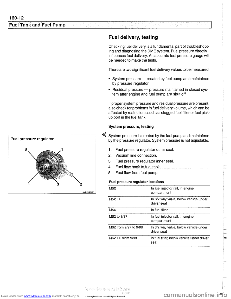
1. Fuel pressure regulator outer seal
4 System pressure is created by the fuel pump and maintained
2. Vacuum line connection.
3. Fuel pressure regulator Inner seal.
4. Fuel flow back to fuel tank.
5. Fuel flow from fuel pump.
Fuel pressure
regulator
Fuel pressure regulator locations
M52 In fuel injector rail, in engine
compartment
M52 TU In 312 way valve, below vehicle under
driver seat
by the pressure
regulator. System pressure is not adjustable.
M54 In fuel filter
M62 to 9/97 In fuel injector rail, in engine
compartment
M62 from 9/97 to 9/98 In 312 way valve, below vehicle under
driver seat
M62 TU from 9/98 In fuel filter, below vehicle under driver
seat
Page 484 of 1002
Downloaded from www.Manualslib.com manuals search engine
. .
I Fuel Tank and Fuel Pump I
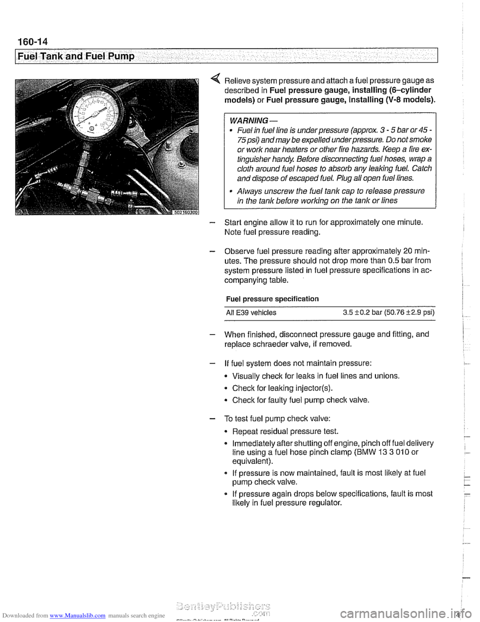
4 Relieve system pressure and attach afuel pressure gauge as
described in Fuel pressure gauge, installing (6-cylinder
models) or Fuel pressure gauge, installing
(V-8 models).
WARNING -
Fuel in fuel line is underpressure (approx. 3 - 5 bar or45 -
75psi) and may be expelled underpressure. Do not smoke
or work near heaters or other fire hazards. Keep a fire ex-
tinguisher handy. Before disconnecting fuel hoses, wrap a
cloth around fuel hoses to absorb any leaking fuel. Catch
and dispose of escaped fuel. Plug all open fuel lines.
. Always unscrew the fuel tank cap to release pressure
in the tank before working on the tank or lines
- Start engine allow it to run for approximately one minute.
Note fuel pressure reading.
- Observe fuel pressure reading after approximately 20 mln-
utes. The pressure should not drop more than 0.5 bar from
system pressure listed in fuel pressure specifications in ac-
companying table.
Fuel pressure specification
Ail
E39 vehicles 3.5 i-0.2 bar (50.76 i2.9 psi)
- When finished, disconnect pressure gauge and fitting, and
replace schraeder valve, if removed.
- If fuel system does not maintain pressure:
Visually check for leaks in fuel lines and unions,
Check for leaking
injector(s).
Check for faulty fuel pump check valve.
- To test fuel pump check valve:
Repeat residual pressure test.
Immediately aftershutting off engine, pinch off fuel delivery
line using a fuel hose pinch clamp (BMW
13 3 010 or
equivalent).
If pressure is now maintained, fault is most likely at fuel
pump check valve.
If pressure again drops below specifications, fault is most
likely in fuel pressure regulator.
Page 494 of 1002
Downloaded from www.Manualslib.com manuals search engine
Fuel Tank and Fuel Pump 1
Activated carbon canister I fuel tank leak
detection unit
(LDP or DMTL), removing . . -
and installing
- Raise rear end of car and support safely.
CAUTION-
Make sure the car is stable and well supported at all times.
Use a professional automotive lift
orjack stands designed for
the purpose.
A floor jack is not adequate support.
- Remove left rear wheel and inner fender panel
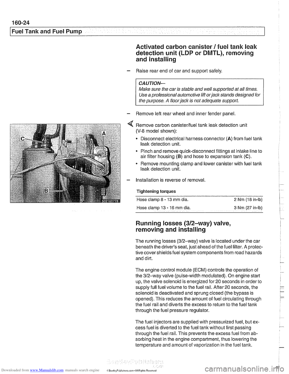
Remove carbon canisterlfuel tank leak detection unit
(V-8 model shown):
Disconnect electrical harness connector
(A) from fuel tank
leak detection unit.
Pinch and remove quick-disconnect fittings at intake line to
air filter housing
(5) and hose to expansion tank (C).
* Remove mounting clamp and lower canister with fuel tank
leak detection unit.
Installation is reverse of removal.
Tightening
torques
Hose clamp 8 - 13 mm dia. 2 Nrn (18 in-lb)
Hose clamp
13 - 16 rnm dia 3 Nm (27 in-lb)
Running losses (312-way) valve,
removing and installing
The running losses (312-way) valve is located under the car
beneath the driver's seat, just ahead of the fuel filter. A protec-
tive covershieldsfuel system components from road hazards
and dirt.
The engine control module
(ECM) controls the operation of
the 312-way valve (pulse-width modulated). On engine start
up, the valve solenoid is energized for 20 seconds in order to
supply full fuel volume to the fuel rail.
After20 seconds, the
solenoid is deactivated and sprung closed (the bypass is
opened). This reduces the amount of fuel circulating through
the fuel rail and diverts the excess to return to the fuel tank
through the fuel pressure regulator.
The fuel injectors are supplied with pressurized fuel, but ex-
cess fuel is diverted to the fuel tank without first passing
through the fuel rail. This prevents the excess fuel from ab-
sorbing heat in the engine compartment, thus lowering the
temperature and amount of vaporization in the fuel tank.
Page 974 of 1002
Downloaded from www.Manualslib.com manuals search engine
OBD-14
I On-Board Diagnostics
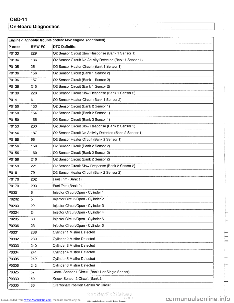
I Engine diagnostic trouble codes: M52 engine (continued) - - -
P-code IBMW-FC ~DTC Definition
PO133
PO134
PO135
PO136
PO136
PO136
PO139
PO141
I I
PO150 1155 102 Sensor Circuit (Bank 2 Sensor 1)
I
I
229
186
25
156
157
215
220 61
PO150 02
Sensor Circuit
Slow Response (Banlc 1 Sensor 1)
02 Sensor Circuit No Activity Detected
(Bank 1 Sensor 1)
02 Sensor Heater Circuit (Bank 1 Sensor 1)
02 Sensor Circuit
(Banlc 1 Sensor 2)
02 Sensor Circuit (Bank 1 Sensor 2)
02 Sensor Circuit (Bank 1 Sensor 2)
02 Sensor Circuit Slow Response
(Bank 1 Sensor 2)
02 Sensor Heater Circuit
(Bank 1 Sensor 2)
PO153
PO154
PO155
PO156
PO156
PO156
PO150 1154 102 Sensor Circuit (Bank 2 Sensor 1)
153
PO159
PO161
PO170
02
Sensor Circuit (Banic 2 Sensor 1)
230
187
55
159
160
21 6
p~-~~--~ PO173
PO201
PO202
PO203
PO204
PO205
PO206
02 Sensor Circuit Slow Response (Banlc 2 Sensor 1)
02 Sensor Circuit No Activity Detected (Bank 2 Sensor
1)
02 Sensor Heater Circuit (Bank 2 Sensor 1)
02 Sensor Circuit (Bank 2 Sensor 2)
02 Sensor Circuit (Banlc 2 Sensor 2)
02 Sensor Circuit (Banlc 2 Sensor 2)
221
79
202 02
Sensor Circuit Slow Response (Banic 2 Sensor 2)
02 Sensor Heater Circuit
(Banic 2 Sensor 2)
Fuel Trim
(Banic 1)
203
6
5
22
24
33
23
Fuel Trim (Banic 2)
injector
Circuitlopen -Cylinder 1
injector
Circuitlopen - Cylinder 2
injector
Circuitlopen -Cylinder 3
Injector
Circuitlopen - Cylinder 4
injector
Circuitlopen - Cylinder 5
lniector
CircuitlOpen - Cvlinder 6
Page 979 of 1002
Downloaded from www.Manualslib.com manuals search engine
On-Board ~ia~nosticsl
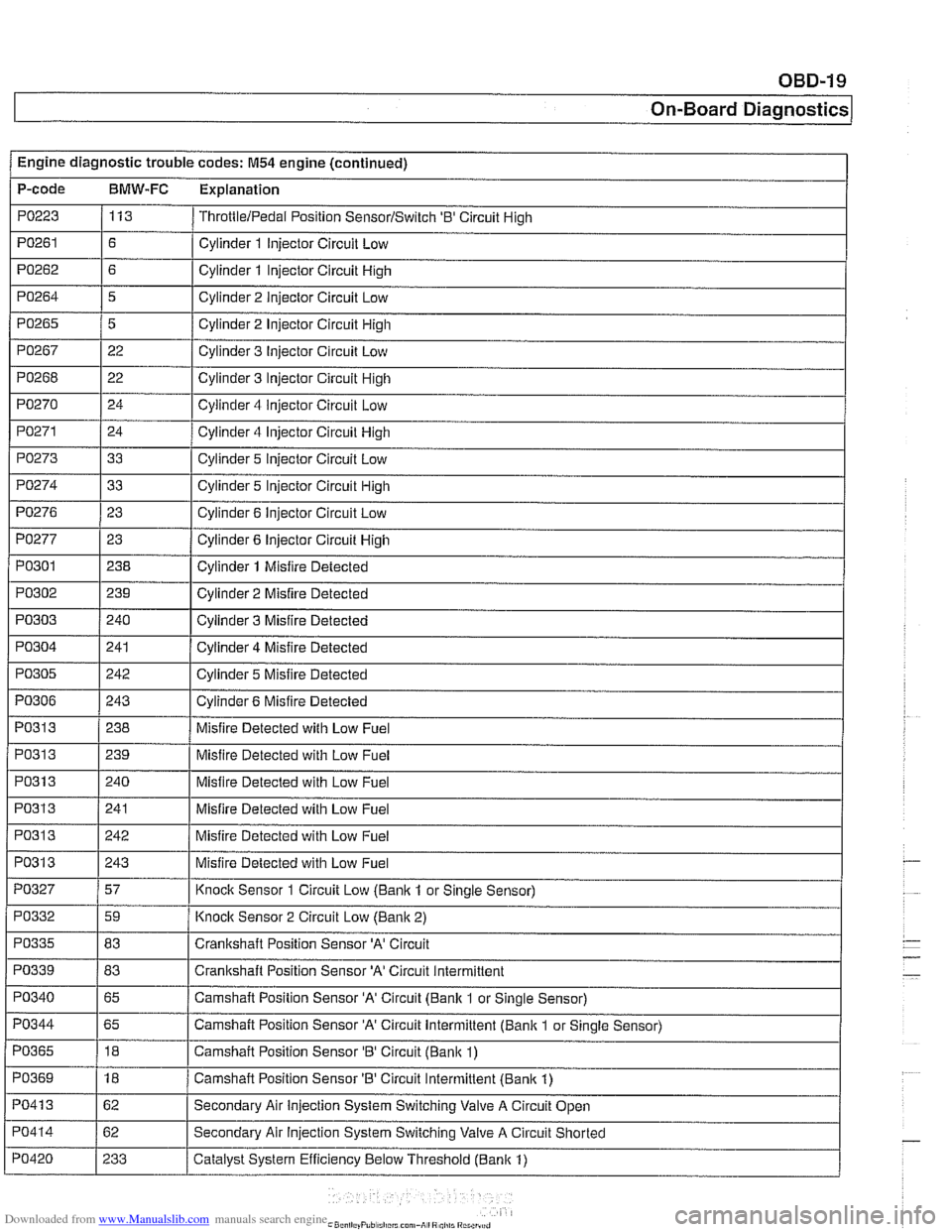
Engine diagnostic trouble codes: M54 engine (continued) I -.
P-code BMW-FC Explanation
PO223 113 ThrottlelPedal Position SensorlSwitch '0' Circuit High
PO261 / Cylinder 1 Injector Circuit Low
PO271 Cylinder 4 Injector Circuit High
PO273 Cylinder 5 Injector Circuit Low
Cylinder 2 Injector Circuit High
Cylinder 3 Injector Circuit
Low
Cylinder 3 Injector Circuit High
Cylinder 4
iniector Circuit Low
PO265
PO267
PO268
PO270
, I
PO277 1 23 1 Cylinder 6 Injector Circuit High
5
22
22
24
I I
PO274
PO301
PO302
PO303
PO304
PO276 1 23 I Cylinder 6 Injector Circuit Low
33
I
I -
I I
PO31 3 1 240 I Misfire Detected with Low Fuel Cylinder 5 Injector Circuit High
238
239
240
241
PO305
I I
Cylinder 1 Misfire Detected
Cylinder 2 Misfire Detected
Cylinder 3 Misfire Detected
Cylinder 4 Misfire Detected
PO313
PO306 1 243 I Cylinder 6 Misfire Detected
242
PO313
PO313
PO31 3
PO327
Cylinder 5 Misfire
Detected
PO31 3 1239 I Misfire Detected with Low Fuel
238
PO332
PO335
PO339 - PO340
Misfire Detected with Low Fuel
241
242
243
57
PO344
PO365
PO369
PO41 3
PO414
PO420
Misfire Detected with Low Fuel
Misfire Detected with Low Fuel
Misfire Detected with Low Fuel
Knock Sensor 1 Circuit Low
(Banlc 1 or Sinale Sensor)
59
83
83
65
-
Knoclc Sensor 2 Circuit Low (Banlc 2)
Crankshaft Position Sensor
'A' Circuit
Crankshaft Position Sensor
'A' Circuit Intermittent
Camshaft Position Sensor 'A' Circuit (Bank 1 or Single Sensor)
65
18
18
62
62
233 Camshaft Position Sensor
'A' Circuit Intermittent (Bank 1
or Single Sensor)
Camshaft Position Sensor
'B' Circuit (Banlc 1)
Camshaft Position Sensor 'B' Circuit Intermittent (Bank 1)
Secondary Air Injection System Switching Valve A Circuit Open
Secondary Air
Injection System Switching Valve A Circuit Shorted
Catalyst System Efficiency Below Threshold (Bank 1)
Page 995 of 1002
Downloaded from www.Manualslib.com manuals search engine
INDEX 5
WARNING
Your common sense, good
judgement, and general alerlness are
crucial lo
safe and successful service ivork. Before attempling any work on
your
BMW be sure lo read 001
General Warnings and Cautions
and the copyright page at the
fronl of
Ihe manual. Review these warnings
and
cautions each lime you prepare
to work on your BMW Please also
read any warnings and cautions tliat
accompany Nie procedures in the
manual.
Exhaust manifold see Exhaust system
Exhaust system diagrams
180.1 1
exhaust manifolds, removinglinstalling
180-4 muifier, replacing 180-8
oxygen sensors 180-8
and catalytic converter 020-1 9
see also Fuel injection
removinglinstalling 180-2
see also Maintenance
Expansion tank
see Cooling system
Expansion valve
see
NC
Exterior lighting
see
Lights
Exterior trim
BMW emblem
(Roundel), removing1
installing
510-13 body side molding, replacing 510.13
grill, removinglinsialiing 510-14
headlight housing trim, removing1
installing 510-14
outside mirror
510-2
EWS (electronic immobilization)
515-21 ring antenna,
iemovinglinstaiting
320-1 1
Fan see Cooling system Fault
codes
OBD-2
storage
100-4. 600.10
Fender
front, rernovinglinstailing
410-2
Filters see Maintenance
Final drive
lubricant
speciiicatiorls 020-9
mounh, replacing 331-12
oil level 020-26. 331-6
removinglinslalling 331-5 seals 331-7
Firing order
see Ignition system
FtS
see Interior protectiorl
Flex disc
see Driveshaft
Fluids and lubricants see Maintenance
Flywheel removinglinstalling 210-13
Fogllght
see Lights
Front centering guide see Driveshatt
Front oil seal
see
Crankshaft oil seals
Front suspension control arm
310-12 description 300-2
ride height 300-14
stabilizer bar, removinglinstalling
310-21
strutslsprings 31
0-4
tension strut 310-16
thrust arm 310-12 variations 310-4
wheel bearing 310-18
see also Maintenance
Fuel filter
see Maintenance
Fuet injection applications 130-2
Bosch M5.2, M5.2.1 130-46
Bosch ME 7.2 130-66 fuel delivery
see 130 under appropriate iuel
injection system
see also Fuel pump
see also
Fuet tank
oxygen sensors
130-72, 180-8
Siemens MS 41.1 130-7 Siemens MS 42.0. MS 43.0 130-23
Fuel injector
see 130 under appropriate fuel
injection system
Fuel level sender
160-15
see also Fuei pump
Fuel pressure
160-10
see also Fuel pump
Fuel pump
160-3
electrical circuit, testino 160-7
1
removinglinstalling (includes right side
iuel levei sender) 160-15
siphon pump, removinglinstaliing
160-19
troubleshooting 160-6 see also Fuel tank
Fuel rail
see 130 under appropriate iuel
injection system
Fuei supply
130-6
see also Fuei pump
see also
Fuet lank
Fuel
tank
312-way valve (running losses.
removinglinstalling
160-24 carbon canister 160-24
draining 160-20
evaporative control system 160-3
expansion tank, removinglinstalling
160-23
I
leak detection unit (LDP or DM-TL),
rernovinoiinstallino 160-24
level senier 160-15
removinglinstalling 160-21
Fuse locations
610-29
RV (remote entry)
see Central
locl(ing
Fan clutch
see Cooling system, cooling fan
Page 996 of 1002
Downloaded from www.Manualslib.com manuals search engine
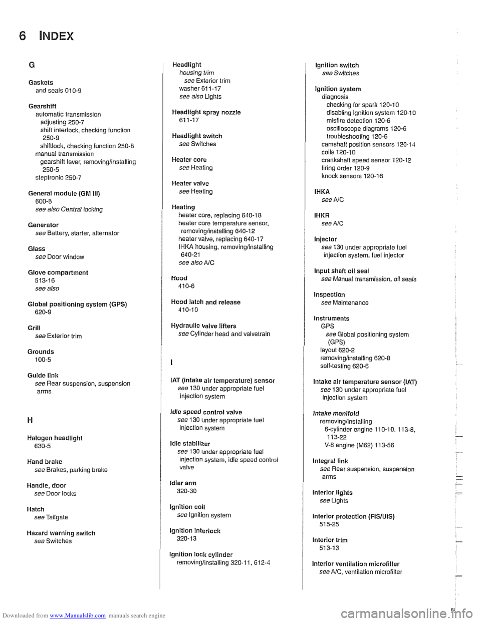
Gaskets and seals 01
0-9
Gearshift automatic transmission
adjusting
250-7
shift interiock. checkino function " 250-9
shiftloclc. checicino function 250-8 - manual transmission
gearshift lever, removingiinstalling
250-5
steptronic 250-7
General module (GM Ill)
600-8
see also Central locking
Generator see Battery, starter, alternator
Glass see Door window
Glove compartment
513-16
see also
Global positioning system
(GPS)
620-9
Grill
see Exterior trim
Grounds
100-5
Guide link
see Rear suspension, suspension
arms
Halogen headlight
630-5
Hand brake
see Brakes, pariring brake
Handle, door
see Door
locks
Hatch seeTailgate
Hazard warning switch
see Switches Headlight
housing trim
see Exterior trim
washer611-17 see also Lights
Headlight spray
nozzle
611-17
Headlight switch
see Switches
Heater core
see Heating
Heater valve
see Heating
Heating lieater core, replacing
640-18
lheater core temperature sensor,
removingiinstalling
640-12 heater valve, replacing 640-17
IHKA housing, removinglinstallin~
640-21
see also NC
Hood
410-6
Hood latch and release
410-10
Hydraulic valve lifters
see Cylinder head and valvetrain
IAT
(lntalce air temperature) sensor
see 130
under appropriate fuel
injection system
idle speed control valve
see 130
under appropriate fuel injection system
Idle stabilizer
see 130
under appropriate fuel
injection system, idie speed controi
valve
idler arm
320-30
lgnition coll
see lgnition system
lgnition interlock
320-13
lgnition lock cylinder
removingiinstalling
320-1 1. 612-4
lgnition switch
seeSwifches
Ignition system
diagnosis checking for
spark 120-10
disabling ignition system 120-10 misfire detection 120-6
oscilioscope diagrams 120.6
troubleshooting 120-6
camshaft position sensors 120-14 coils 120.10
crankshaft speed sensor 120-12 firing order 120-9
knoclc sensors 120-16
IHKA
see NC
IHKR see NC
Injector
see 130 under appropriate
fuel
injection system, luel injector
Input shaft
oil seal
see Manual transmission, oil seals
Inspection
see Maintenance
Instruments GPS see Global positioning system
(GPSI layout 6202
removingiinstalling 620-8 self-testing 620-6
Intake air temperature sensor (IAT)
see 130 under appropriate fuel
injection system
Intake manifold
removingiinstalling
6-cvlinder enoine 110-10. 113-8. 113-22 -
V-8 engine (M62) 113-56
Integral link
see Rear suspension, suspension
arms
lnterior lights
see Lights
lnterior protection
(FISIUIS) 515-25
lnterior trim
513-13
lnterior ventilation microfilter see
NC, ventilation microfiller