electrical BMW 528i 2000 E39 Workshop Manual
[x] Cancel search | Manufacturer: BMW, Model Year: 2000, Model line: 528i, Model: BMW 528i 2000 E39Pages: 1002
Page 499 of 1002
Downloaded from www.Manualslib.com manuals search engine
- -
L- -
--
-. - - - Radiator and Cooling sYstelll/ --
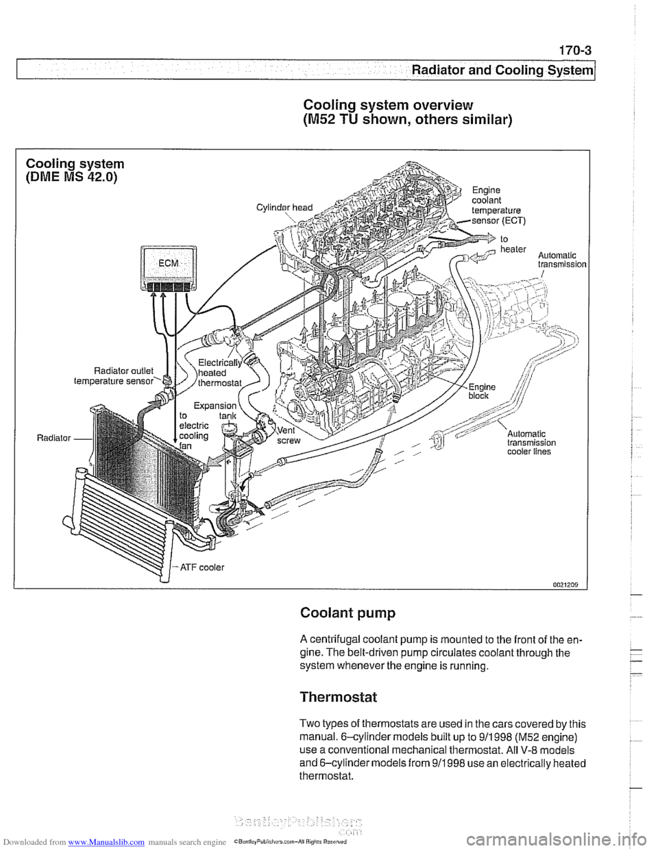
Cooling system overview
(M52 TU shown, others similar)
Coolant pump
A centrifugal coolant pump is mounted to the front of the en-
gine. The belt-driven pump circulates coolant through the
system whenever the engine is running.
Thermostat
Two types of thermostats are used in the cars covered by this
manual. 6-cylinder models built up to
911 998 (M52 engine)
use a conventional mechanical thermostat. All
V-8 models
and 6-cylinder models from
911998 use an electrically heated
thermostat.
Page 500 of 1002
Downloaded from www.Manualslib.com manuals search engine
-
I Radiator and Cooling System
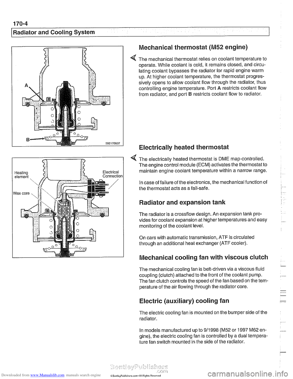
Mechanical thermostat
(M52 engine)
4 The mechanical thermostat relies on coolant temperature to
operate. While coolant is cold, it remains closed, and circu-
lating coolant bypasses the radiator for rapid engine warm
up. At higher coolant temperature, the thermostat progres-
sively opens to allow coolant flow through the radiator, thus
controlling engine temperature. Port
A restricts coolant flow
from radiator, and port
B restricts coolant flow to radiator.
Electrically heated thermostat
4 The electrically heated thermostat is DME map-controlled.
The engine control module (ECM) activates the thermostat to
maintain engine coolant temperature within a narrow range.
In case of failure of the electronics, the mechanical function of
the thermostat acts as a fail-safe.
Radiator and expansion tank
The radiator is a crossflow design. An expansion tank pro-
vides for coolant expansion at higher temperatures and easy
monitoring of the coolant level.
On cars with automatic transmission, ATF is circulated
through an additional heat exchanger (ATF cooler).
Mechanical cooling fan with viscous clutch
The mechanical cooling fan is belt-driven via a viscous fluid
coupling (clutch) attached to the front of the coolant pump.
The fan clutch controls the speed of the fan based on the tem-
perature of the air flowing through the radiator core.
Electric (auxiliary) cooling fan
The electric cooling fan is mounted on the bumper side of the
radiator.
In models manufactured up to
911 998 (M52 or 1997 M62 en-
gine), the electric cooling fan is controlled by a dual tempera-
ture fan switch mounted in the side of the radiator.
Page 504 of 1002
Downloaded from www.Manualslib.com manuals search engine
170-8
I Radiator and Cooling System
Common cooling system faults can be grouped into one of 4
categories:
Cooling system
lealts
Poor coolant circulation
Radiator cooling fan faults
Electrical/electronic faults
Cooling system inspection
- Check that coolant pump drive belt tensioner is functioning
properly and that belt tension is correct. Belt tensioner sys-
tems for the different models are shown in
020 Maintenance.
- Check condition of coolant pump drive belt.
- Checlc coolant hoses for cracks or softness. Checlc clamps
for looseness. Check coolant level and check for evidence of
coolant
lealts from engine.
- Check that radiator fins are not blocked with dirt or debris.
Clean radiator using low-pressure water or compressed air.
Blow outward, from engine side out.
- To check coolant pump:
Remove mechanical cooling fan. See Mechanical
(vis.
cous clutch) cooling fan, removing and installing.
Remove drive belt from coolant pump pulley. See
020
Maintenance.
Firmly grasp opposite sides of pulley and check for play in
all directions.
Spin pulley and check that shaft runs smoothly without
play.
NOTE-
The coolant provides lubrication for the pump shaft, so an oc-
casional drop of coolant
lealing from the pump is acceptable.
If coolant drips steadily from the vent hole, replace the pump.
- At normal engine operating temperature, cooling system is
pressurized. This raises boiling point of coolant.
Leaks may
prevent system from becoming pressurized. If visual evi-
dence is inconclusive, pressure test cooling system as de-
scribed later to help pinpoint hard-to-find leaks.
- If cooling system is full of coolant and holds pressure:
- Use an appropriate scan tool to interrogate engine control
module (ECM) for radiator fan or DME control circuit faults.
Checlc for loose or worn drive belt.
0 Test for failed thermostat or coolant pump impeller. Some
pumps may be fitted with plastic impellers.
Page 511 of 1002
Downloaded from www.Manualslib.com manuals search engine
Radiator and Cooling System
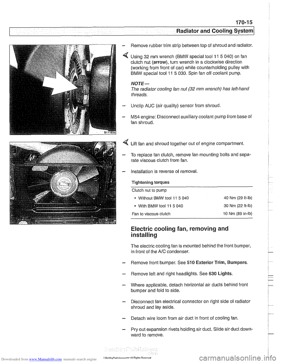
Remove rubber trim strip between top of shroud and radiator.
Using 32 mm wrench
(BMW special tool 11 5 040) on fan
clutch nut (arrow), turn wrench in a clockwise direction
(working from front of car) while counterholding pulley with
BMW special tool
11 5 030. Spin fan off coolant pump.
NOTE-
The radiator cooling fan nut (32 mm wrench) has left-hand
threads.
Unclip AUC (air quality) sensor from shroud,
M54 engine: Disconnect auxiliary coolant pump from base of
fan shroud.
Lift fan and shroud together out of engine compartment.
To replace fan clutch, remove fan mounting bolts and sepa-
rate viscous clutch from fan.
Installation is reverse of removal.
Tightening
torques
Clutch nut to pump
Without
BMW tool 11 5 040 40 Nm (29 ft-lb)
With BMW tool 11 5 040 30 Nm
(22 ft-lb)
Fan to viscous clutch 10 Nm (89 in-lb)
Electric cooling fan, removing and
installing
The electric cooling fan is mounted behind the front bumper,
in front of the
A/C condenser.
- Remove front bumper. See 510 Exterior Trim, Bumpers.
- Remove left and right headlights. See 630 Lights,
- Where applicable, detach horizontal air ducts behind front
bumper and fold to side.
- Disconnect fan electrical connector on right side of radiator
shroud and lay aside.
- Detach wire loom from air duct in front of cooling fan
- Pry out expansion rivets holding air duct. Slide air duct down-
ward to remove.
Page 513 of 1002
Downloaded from www.Manualslib.com manuals search engine
Radiator and Cooling systeml
Tightening torques
Block drain plug to block 25 Nm
(18
it-lb)
Coolant hose clamp (32 - 48 2.
5 Nm (22 in-lb)
mm hose diameter)
Radiator drain plug to radiator
2-3Nm(l8-27in-lb)
Thermostat housing to cylinder
head 10 Nm (89 in-lb)
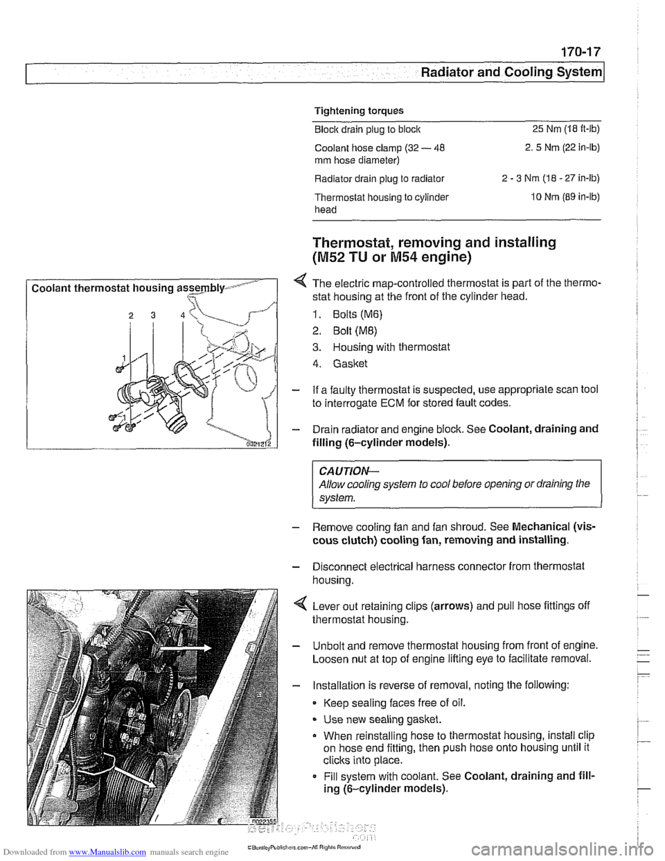
I Coolant thermostat housing assmbly- - I
Thermostat, removing and installing
(M52 TU or M54 engine)
4 The electric map-controlled thermostat is part of the thermo-
stat housing at the front of the cylinder head.
1. Bolts (M6)
2 Bolt (ME)
3. Housing with thermostat
4. Gasket
- If a faulty thermostat is suspected, use appropriate scan tool
to interrogate
ECM for stored fault codes.
- Drain radiator and engine block. See Coolant, draining and
filling (6-cylinder models).
CAUTION-
Allow cooling system to cool before opening or draining the
system.
- Remove cooling fan and fan shroud. See Mechanical (vis-
cous clutch) cooling fan, removing and installing.
- Disconnect electrical harness connector from thermostat
housina.
4 Lever out retaining clips (arrows) and pull hose fittings off
thermostat housing.
- Unbolt and remove thermostat housing from front of engine.
Loosen nut at top of engine lifting eye to facilitate removal.
- Installation is reverse of removal, noting the following:
Keep sealing faces free of oil.
* Use new sealing gasket.
When reinstalling hose to thermostat housing, install clip
on hose end fitting, then push hose onto housing until it
clicks into place.
Fill system with coolant. See Coolant, draining and fill-
ing (6-cylinder models).
Page 514 of 1002
Downloaded from www.Manualslib.com manuals search engine
Tightening torques Block drain plug to block
25 Nm (18 ft-lb)
Radiator drain plug to radiator 2 - 3 Nm (18 - 27 in-lb)
Thermostat housing to
cylinder head 10 Nm (89 in-lb)
Thermostat, removing and installing
(V-8 models)
The electrically-heated thermostat is an integral parl of the
thermostat housing. The operation of the thermostat is moni-
tored by the engine control module (ECM).
- If a faulty thermostat is suspected, use appropriate scan tool
to interrogate ECM for stored fault codes.
- Drain radiator and engine block. See Coolant, draining and
filling
(V-8 models).
WARNING -
Allow cooling system to cool before opening or draining the
system.
- Disconnect mass air flow (MAF) sensor electrical harness
connector. Remove air intake duct together with MAF sensor.
- Remove mechanical cooltng fan and fan shroud. See Me-
chanical (viscous clutch) cooling fan, removing and
in-
stalling.
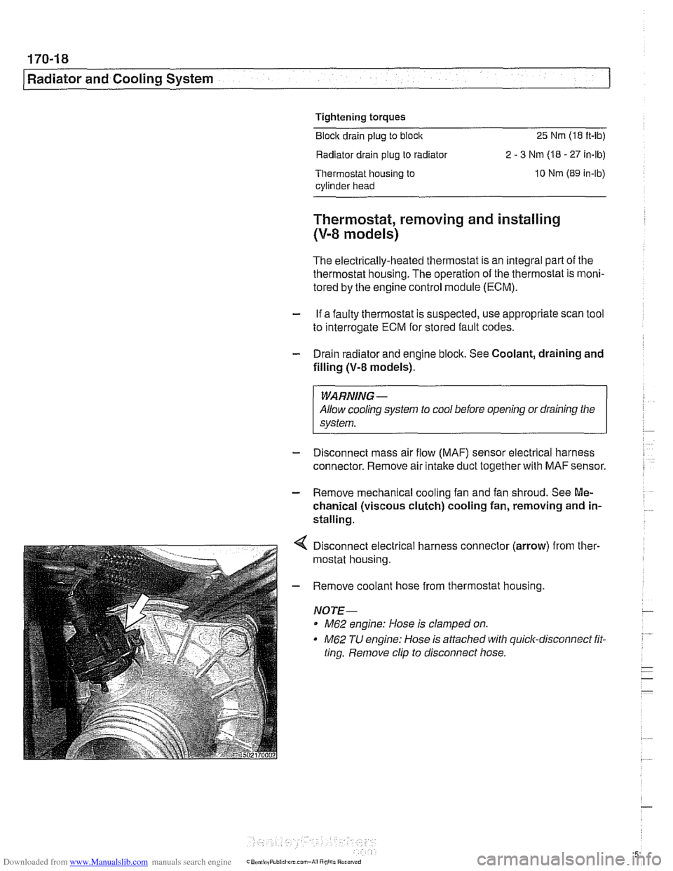
Disconnect electrical harness connector (arrow) from ther-
mostat housing.
Remove coolant hose from thermostat housing.
NOTE-
M62 engine: Hose is clamped on.
M62 TU engine: Hose is attached with quick-disconnect fit.
ting. Remove clip to disconnect hose.
Page 516 of 1002
Downloaded from www.Manualslib.com manuals search engine
.," --
Radiator and Cooling System --- 1
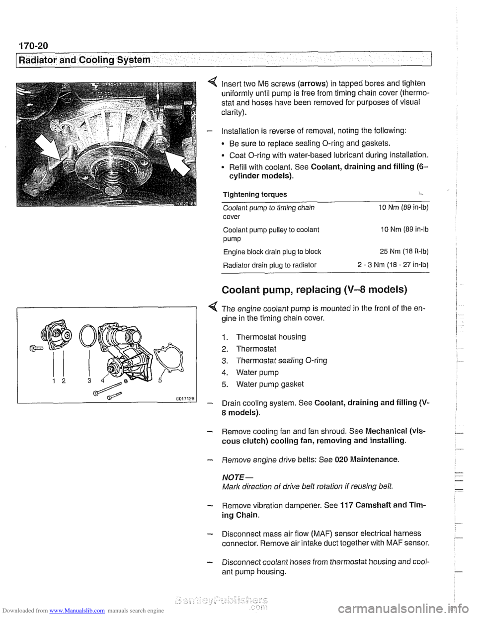
insert two M6 screws (arrows) in tapped bores and tighten
uniformly until pump is free from timing chain cover (thermo-
stat and hoses have been removed for purposes of visual
clarity).
Installation is reverse of removal, noting the following:
Be sure to replace sealing O-ring and gaskets.
Coat O-ring with water-based lubricant during installation.
Refill with coolant. See Coolant, draining and filling
(6-
cylinder models).
Tightening torques
-
Coolant pump to timing chain 10 Nm (89 in-lb)
cover
Coolant pump pulley to coolant
10 Nm (89 in-lb
pump
Engine block drain plug to block 25 Nm (1 8 It-lb)
Radiator drain plug to radiator 2 - 3 Nm (I8 - 27 in-lb)
Coolant pump, replacing (V-8 models)
I 1 < The engine coolant pump is mounted in the front of the en-
gine in ;he timing chain cover.
1. Thermostat housing
2. Thermostat
3. Thermostat sealing O-ring
4. Water pump
5. Water pump gasket
- Drain cooling system. See Coolant, draining and filling (V-
8 models).
- Remove cooling fan and fan shroud. See Mechanical (vis-
cous clutch) cooling fan, removing and installing.
- Remove engine drive belts: See 020 Maintenance.
NOTE-
Mark direction of drive belt rotation if reusing belt,
- Remove vibration dampener. See 117 Camshaft and Tim-
ing Chain.
- Disconnect mass air flow (MAF) sensor electrical harness
connector. Remove air intake duct together with
MAF sensor.
- Disconnect coolant hoses from thermostat housing and cool-
ant pump housing.
Page 518 of 1002
Downloaded from www.Manualslib.com manuals search engine
.. - --
Radiator and Cooling System
Tightening torques
Coolant pump to timing chain 10
Nm (89 in-lb)
cover
Coolant pump
pulley to coolant
pump
10 Nm (89 in-lb
Engine
blocic drain plug to block 25 Nm (18 ft-lb)
Radiator drain plug to radiator
2-3Nm(18-27in-lb)
Thermostat cover to coolant
pump assembly 10 Nm (89 in-lb)
Radiator, removing and installing
Removal of the radiator is similar for V-8 and 6-cylinder mod-
els.
- Raise front of car and support safely.
WARNING -
Make sure the car is stable and well supported at aN times.
Use a professional automotive liff
orjaclc stands designed for
- Remove splash shield from under engine.
- Drain radiator and engine block. See Coolant, draining and
filling
(V-8 models).
WARNING -
Allow cooling system to cool before opening or draining sys-
tem.
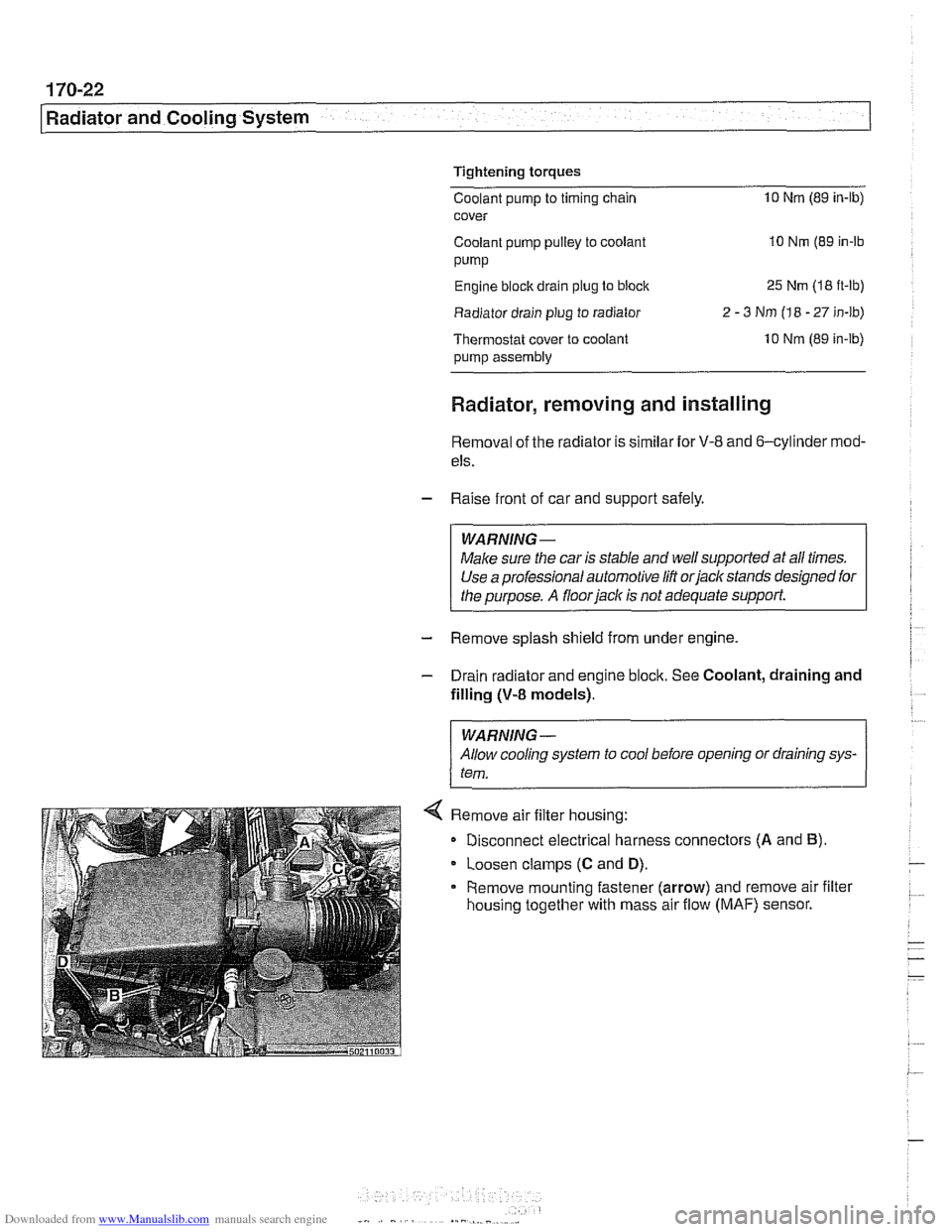
< Remove air filter housing:
Disconnect electrical harness connectors
(A and B).
Loosen clamps (C and D).
Remove mounting fastener (arrow) and remove air filter
housing together with mass air flow
(MAF) sensor.
Page 519 of 1002
Downloaded from www.Manualslib.com manuals search engine
. --
Radiator and Cooling system/
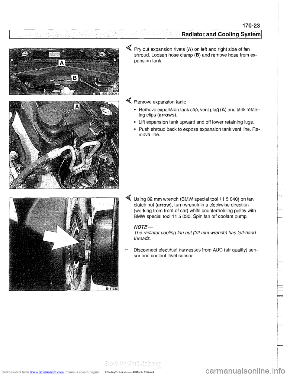
4 Pry out expansion rivets (A) on left and right side of fan
shroud. Loosen hose clamp
(6) and remove hose from ex-
pansion tank.
Remove expansion tank: Remove expansion tanlc cap, vent plug
(A) and tank retain-
ing clips (arrows).
Lift expansion
tanlc upward and off lower retaining lugs.
Push shroud back to expose expansion tank vent line. Re-
move line.
Using 32 mm wrench
(BMW special tool 11 5 040) on fan
clutch nut (arrow), turn wrench in a clockwise direction
(working from front of car) while counterholding pulley with
BMW special tool 11 5 030. Spin fan off coolant pump.
NOTE-
The radiator cooling fan nut (32 mrn wrench) has left-hand
threads.
Disconnect electrical harnesses from
AUC (air quality) sen-
sor and coolant level sensor.
Page 546 of 1002
Downloaded from www.Manualslib.com manuals search engine
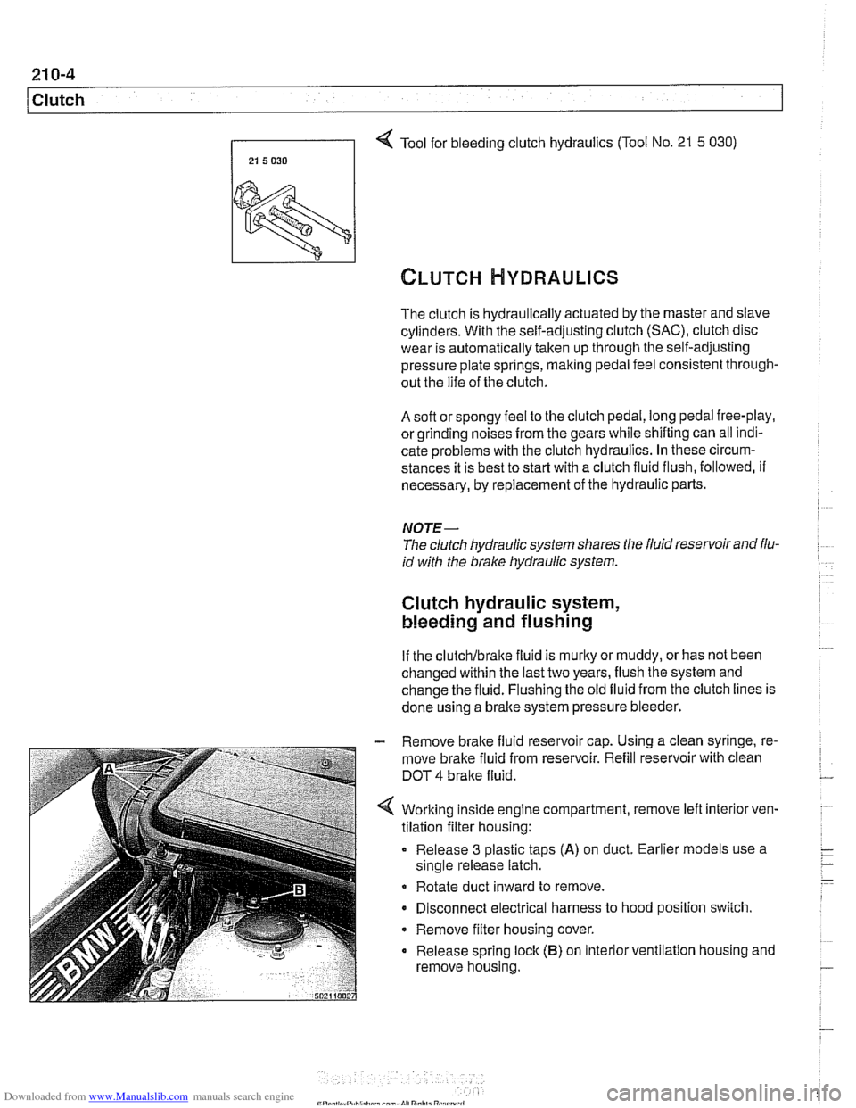
Tool for bleeding clutch hydraulics (Tool No. 21 5 030)
21 5 030 I
The clutch is hydraulically actuated by the master and slave
cylinders. With the self-adjusting clutch
(SAC), clutch disc
wear is automatically taken up through the self-adjusting
pressure plate springs, making pedal feel consistent through-
out the life of the clutch.
A soft or spongy feel to the clutch pedal, long pedal free-play,
or grinding noises
from the gears while shifting can all indi-
cate problems with the clutch hydraulics. In these circum-
stances it is best to
star? with a clutch fluid flush, followed, if
necessary, by replacement of the hydraulic parts.
NOTE-
The clutch hydraulic system shares the fluid reservoir and flu-
id with the brake hydraulic system.
Clutch hydraulic system,
bleeding and flushing
If the clutchlbralte fluid is murky or muddy, or has not been
changed within the last two years, flush the system and
change the fluid. Flushing the old fluid from the clutch lines is
done using a bralte system pressure bleeder.
- Remove brake fluid reservoir cap. Using a clean syringe, re-
move brake fluid from reservoir. Refill reservoir with clean
DOT
4 bralte fluid.
Worlting inside engine compartment, remove left
interiorven-
tilation filter housing:
Release 3 plastic taps
(A) on duct. Earlier models use a
single release latch.
Rotate duct inward to remove.
Disconnect electrical harness to hood position switch.
Remove filter housing cover.
Release spring lock
(B) on interior ventilation housing and
remove housing.