Crankshaft position sensor BMW 528i 2000 E39 User Guide
[x] Cancel search | Manufacturer: BMW, Model Year: 2000, Model line: 528i, Model: BMW 528i 2000 E39Pages: 1002
Page 454 of 1002
Downloaded from www.Manualslib.com manuals search engine
-
Fuel Injection
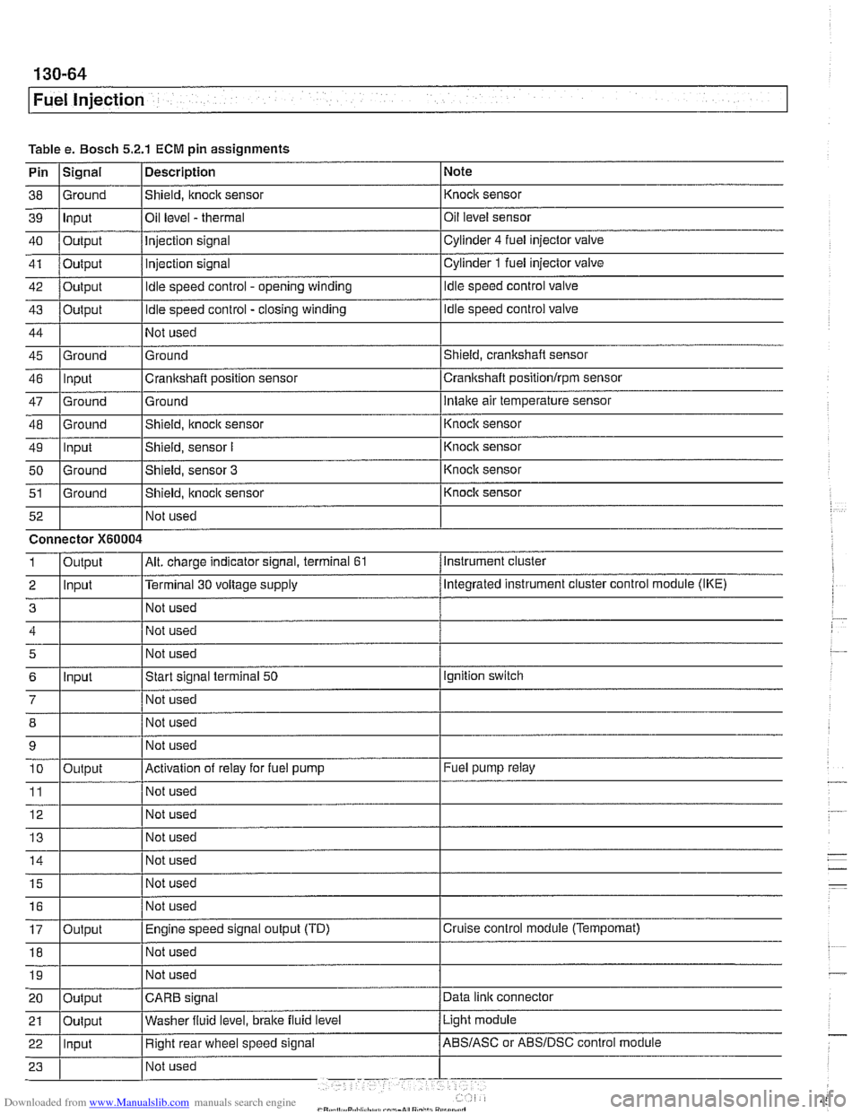
Table e. Bosch 5.2.1 ECM pin assignments
Pin
I~iqnal 1 Description 1 Note
I I I
46 llnput ICrankshaft position sensor Icrankshaft positionlrpm sensor
38
39
40
41
42
43
44
45 Ground Input
Output
Output
Output
Output
Ground
47
48
49
50
51
Not used
I Not used
52
Shield, knock sensor
Oil level
- thermal
Injection signal
injection signal
Idle speed control - opening winding
Idle speed control - closing winding
Not used
Ground
Ground
-- Ground Input
Ground
Ground Not used Knock sensor
Oil level sensor
Cylinder
4 fuel injector
valve
Cylinder
1 fuel injector valve
Idle speed control valve
Idle speed control valve
Shield, crankshaft sensor
5
6
7
12 Not used
Ground
Intake air temperature sensor
Connector
X60004
8
9 10
11
14 1 1 Not used I
Shield, knock sensor
Shield, sensor
I
Shield, sensor 3
Shield, itnock sensor
Input
- Knoclc sensor
Knock sensor
Knock sensor
Knock sensor
Instrument cluster
Output
2 llnput l~erminal 30 voltage supply /Megrated instrument cluster control module (IKE)
Alt. charge indicator signal, terminal 61 1
Not used
Start signal terminal
50
Not used
15
16
17
18
Output
Ignition switch
Not used
Not used
Activation of relay for fuel pump
Not used
19
Fuel pump relay
Output Not used
I I I 20 loutput ICARB signal /Data link connector
Not
used
Not used
Engine speed signal output (TD)
Not used
Light module
21
Cruise control module (Tempomat)
22 llnput I Right rear wheel speed signal /ABS/ASC or ABSIDSC control module
Oulput
Washer
fluid level,
brake fluid level
Page 458 of 1002
Downloaded from www.Manualslib.com manuals search engine
130-68
Fuel Injection
0
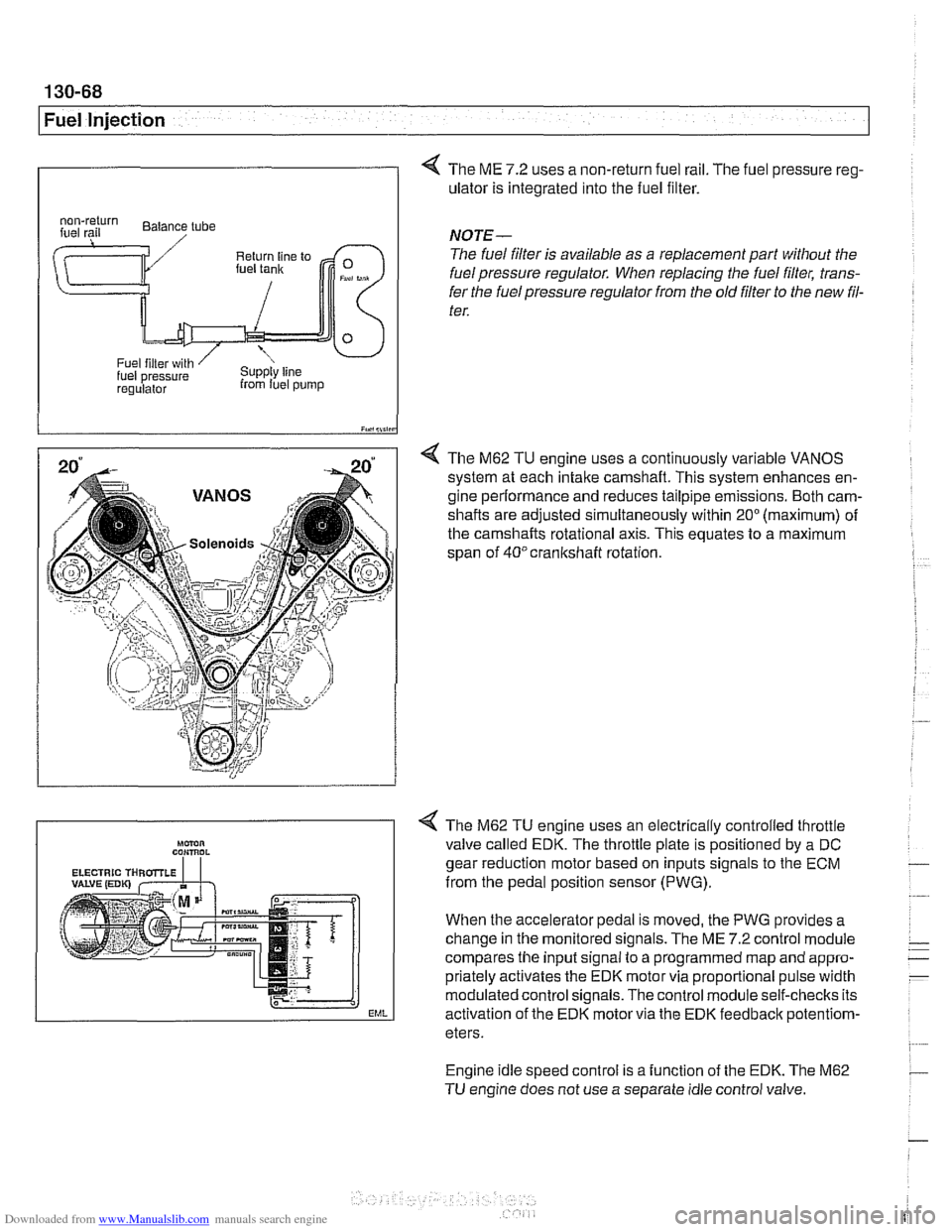
4 The ME 7.2 uses a non-return fuel rail. The fuel pressure reg-
ulator is integrated into the fuel filter.
I iY.,lii,in
4 The M62 TU engine uses a continuously variable VANOS
system at each intake camshaft. This system enhances en-
gine performance and reduces tailpipe emissions. Both cam-
shafts are adjusted simultaneously within
20" (maximum) of
the camshafts rotational axis. This equates to a maximum
span of
40°crankshaft rotation.
regulalor from luel pump
NOTE-
The fuel filter is available as a replacement part without the
fuel pressure regulator. When replacing the fuel filter, trans-
fer the fuel pressure regulator from the old
filter to the new fil-
ter.
Engine idle speed control is a function of the EDK. The M62
TU engine does not use a separate idle control valve.
Mmn CON,ROL
EML
< The M62 TU engine uses an electrically controlled throttle
valve called EDK. The throttle plate is positioned by a DC
gear reduction motor based on inputs signals to the ECM
from the pedal position sensor (PWG).
When the accelerator pedal is moved, the PWG provides a
change in the monitored signals. The ME
7.2 control module
compares the input signal to a programmed map and appro-
priately activates the EDK motor via proportional pulse width
modulated control signals. The control module self-checks its
activation of the EDK motor via the EDK feedbaclc
potentiom-
eters.
Page 468 of 1002
Downloaded from www.Manualslib.com manuals search engine
I Fuel Injection
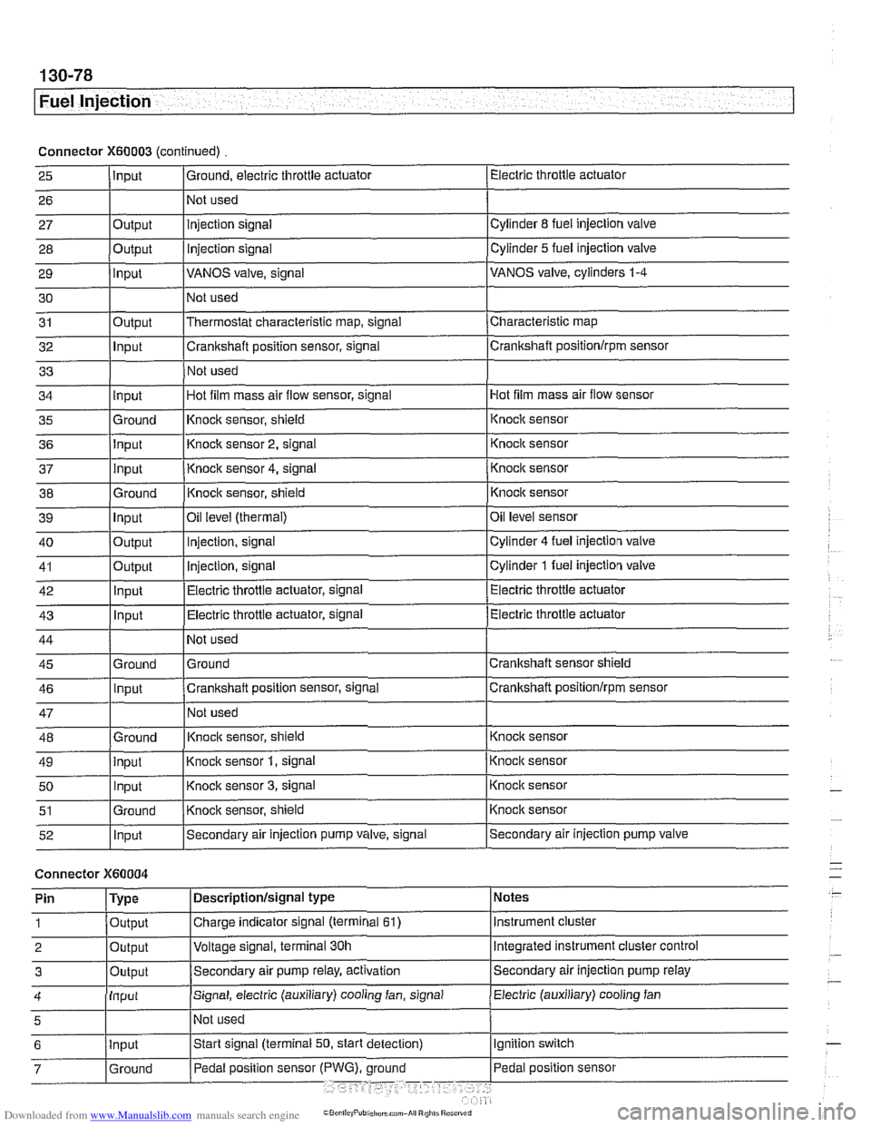
Connector X60003 (continued) Electric throttle actuator
25
- 27 28
29
30
31
32
33
I I I
36 jlnput I Knoclc sensor 2, signal 1 Knock sensor
I I I
Input
26
Output
Output
input
Output
Input
I ' I . I
43 1 ln~ut I Electric throttle actuator, signal (Electric throttle actuator
Ground, electric throttle actuator
1 Not
used
Hot film mass air flow sensor
34
- 37
38
39
40
41
42
injection signal
Injection
signal
VANOS valve, signal
Not used
Thermostat characteristic map, signal
Crankshaft position sensor, signal
Not used
35 l~round I~nock sensor, shield 1 ~nock sensor
Cylinder
8 fuel injection valve
Cylinder
5 fuel injection valve
VANOS valve, cylinders
1-4
Characteristic map
Crankshaft positionlrpm sensor
input
input
Ground
Input
Output
Output
Innut
Hot film mass air flow sensor, signal
I
44
45 46
47
48
49
50
51
52
Connector )(GO004
Knock sensor 4, signal
Knock sensor, shield
Oil
level (thermal)
Injection, signal
Injection, signal
Electric throttle actuator, signal
Not used
Ground
Crankshaft position sensor, signal
Not used
Knoclc sensor, shield
Knock sensor
1, signal
Knock sensor
3, signal
Knock sensor, shield
Secondary air injection pump valve, signal
'
Ground
Input
Ground
input Input
Ground
Input
I' I ... I . ~
Knock sensor
Knocic sensor
Oil level sensor
Cylinder
4 fuel injection valve
Cylinder
1 fuel injection valve
Electric throttle actuator
Crankshaft sensor shield
Crankshaft
positionlrprn sensor
Knock sensor
Knock sensor
Knock sensor
Knock sensor
Secondary air injection pump valve
Notes
Instrument cluster
Integrated instrument cluster control
Secondary air injection pump
relay
Pin
1
2
3
Electric (auxiliary) cooling fan 4
Type
Output
Output
Outout
Descriptionlsignal type
Charge indicator signal (terminal
61)
Voltage signal, terminal 30h
Secondam air pump relay, activation
Input
5
Signal, electric (auxiliary) cooling fan, signal
I~ot used
Page 556 of 1002
Downloaded from www.Manualslib.com manuals search engine
210-1 4
1 Clutch
Dowel sleeve I
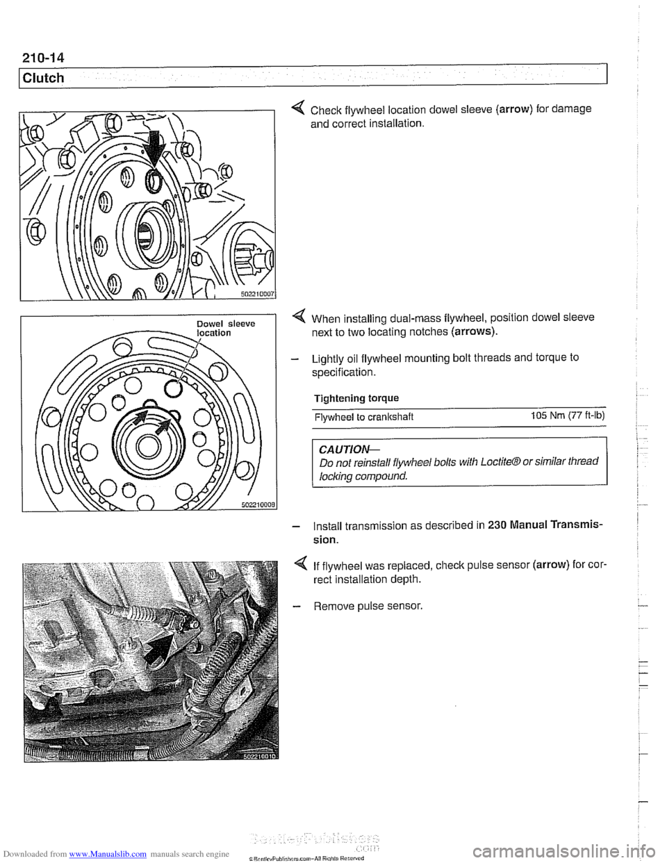
Check flywheel location
and correct installation. dowel sleeve
(arrow)
for . damage
< When installing dual-rnass flywheel, position dowel sleeve
next to two locating notches (arrows).
- Lightly oil flywheel mounting bolt threads and torque to
specification.
Tightening torque
Flywheel to crankshaft 105 Nm (77 ft-lb)
CAUTIOI\C
Do not reinstall flywheel bolls with LoctiteCTJ or similar thread
locl~ing compound.
- Install transm~ssion as descr~bed in 230 Manual Transmis-
sion.
4 If flywheel was replaced, check pulse sensor (arrow) for cor.
rect installation depth.
- Remove pulse sensor.
Page 979 of 1002
Downloaded from www.Manualslib.com manuals search engine
On-Board ~ia~nosticsl
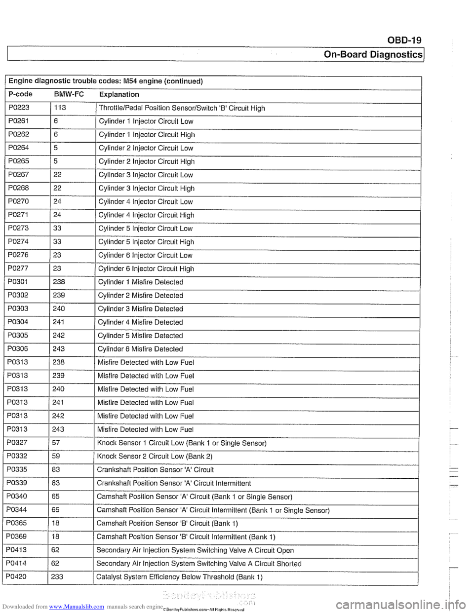
Engine diagnostic trouble codes: M54 engine (continued) I -.
P-code BMW-FC Explanation
PO223 113 ThrottlelPedal Position SensorlSwitch '0' Circuit High
PO261 / Cylinder 1 Injector Circuit Low
PO271 Cylinder 4 Injector Circuit High
PO273 Cylinder 5 Injector Circuit Low
Cylinder 2 Injector Circuit High
Cylinder 3 Injector Circuit
Low
Cylinder 3 Injector Circuit High
Cylinder 4
iniector Circuit Low
PO265
PO267
PO268
PO270
, I
PO277 1 23 1 Cylinder 6 Injector Circuit High
5
22
22
24
I I
PO274
PO301
PO302
PO303
PO304
PO276 1 23 I Cylinder 6 Injector Circuit Low
33
I
I -
I I
PO31 3 1 240 I Misfire Detected with Low Fuel Cylinder 5 Injector Circuit High
238
239
240
241
PO305
I I
Cylinder 1 Misfire Detected
Cylinder 2 Misfire Detected
Cylinder 3 Misfire Detected
Cylinder 4 Misfire Detected
PO313
PO306 1 243 I Cylinder 6 Misfire Detected
242
PO313
PO313
PO31 3
PO327
Cylinder 5 Misfire
Detected
PO31 3 1239 I Misfire Detected with Low Fuel
238
PO332
PO335
PO339 - PO340
Misfire Detected with Low Fuel
241
242
243
57
PO344
PO365
PO369
PO41 3
PO414
PO420
Misfire Detected with Low Fuel
Misfire Detected with Low Fuel
Misfire Detected with Low Fuel
Knock Sensor 1 Circuit Low
(Banlc 1 or Sinale Sensor)
59
83
83
65
-
Knoclc Sensor 2 Circuit Low (Banlc 2)
Crankshaft Position Sensor
'A' Circuit
Crankshaft Position Sensor
'A' Circuit Intermittent
Camshaft Position Sensor 'A' Circuit (Bank 1 or Single Sensor)
65
18
18
62
62
233 Camshaft Position Sensor
'A' Circuit Intermittent (Bank 1
or Single Sensor)
Camshaft Position Sensor
'B' Circuit (Banlc 1)
Camshaft Position Sensor 'B' Circuit Intermittent (Bank 1)
Secondary Air Injection System Switching Valve A Circuit Open
Secondary Air
Injection System Switching Valve A Circuit Shorted
Catalyst System Efficiency Below Threshold (Bank 1)
Page 987 of 1002
Downloaded from www.Manualslib.com manuals search engine
On-Board ~ia~nosticsl
I I
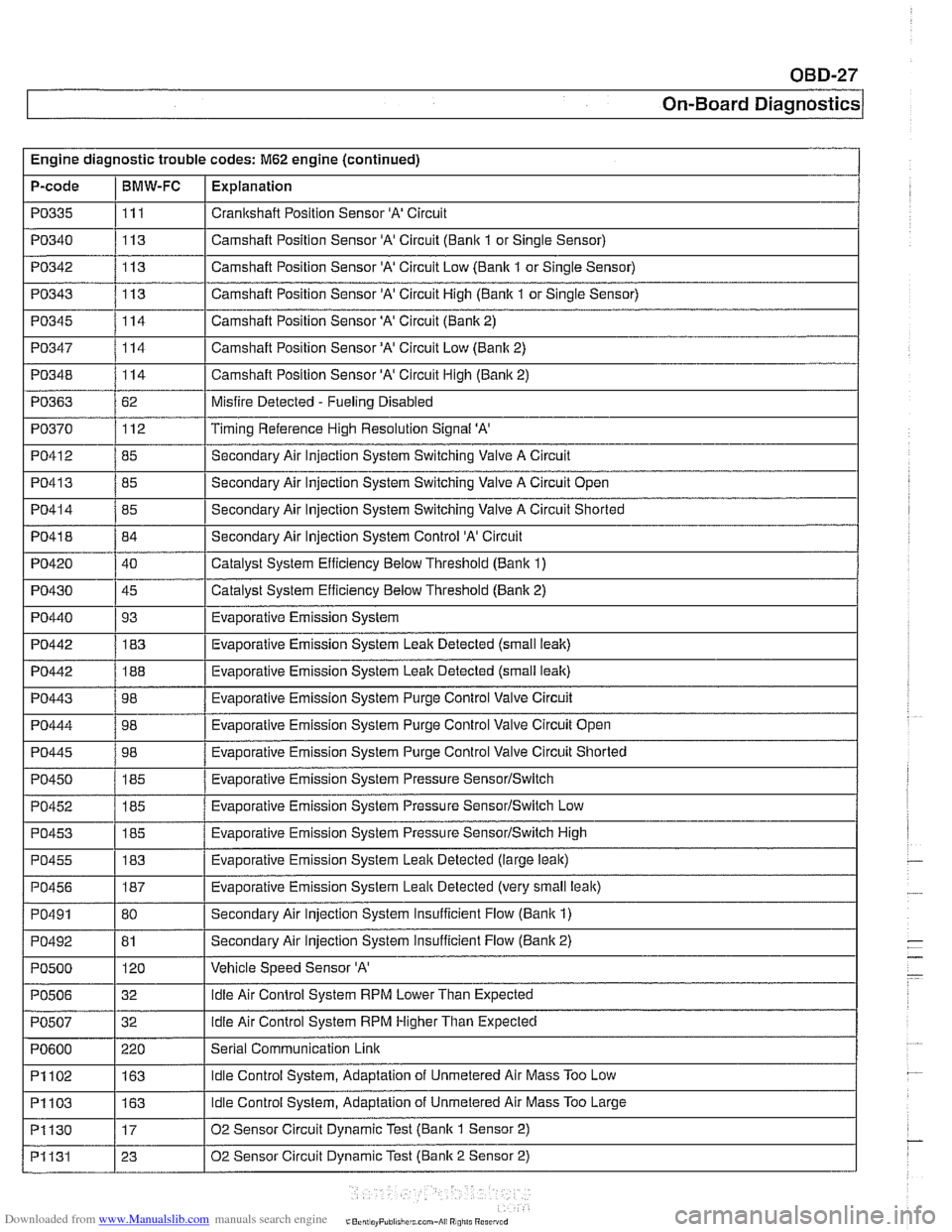
PO340 1113 I Camshaft Position Sensor 'A' Circuit (Bank 1 or Single Sensor)
Engine
diagnostic trouble codes:
M62 engine (continued)
P-code
PO342
PO343
PO345
PO347
PO348
PO363
PO370
PO41 2
PO335 I111 I Crankshaft Position Sensor 'A' Circuit
BMW-FC
I I -
I I -
PO445 1 98 1 Evaporative Emission System Purge Control Valve Circuit Shorted
Explanation
113
113
114
114
114
62 112
85
PO41 3
PO41 8
PO420
PO430
PO440
PO442
PO442
PO443
PO444
Camshaft Position Sensor 'A' Circuit Low (Bank 1 or Single Sensor)
Camshaft Position Sensor
'A' Circuit High (Bank 1 or Single Sensor)
Camshaft Position Sensor
'A' Circuit (Bank 2)
Camshaft Position
Sensor'A' Circuit Low (Bank 2)
Camshaft Position Sensor 'A' Circuit High
(Banic 2)
Misfire Detected
- Fueling Disabled
Timing Reference High Resolution Signal
'A'
Secondary Air lniection System Switchinq Valve A Circuit
PO41 4 / 85 I Secondary Air Injection System Switching Valve A Circuit Shorted
85
84
40
45 93 183
188
98
98
PO450
PO452
PO453
PO455
PO456
PO491
PO492
PO500
PO506
I I
PI102 1163 I Idle Control System, Adaptation of Unmetered Air Mass Too Low
Secondary
Air Injection System Switching Valve A Circuit Open
Secondary Air Injection System Control
'A' Circuit
Catalyst System Efficiency Below Threshold (Bank 1)
Catalyst System Efficiency
Below Threshold (Bank 2)
Evaporative Emission System
Evaporative Emission System Leak Detected (small
leak)
Evaporative Emission System Leak Detected (small leak)
Evaporative Emission System Purge Control Valve Circuit
Evaporative Emission System Purqe Control Valve Circuit Open
I
I
185
185
185
183
187
80
81 120
32
PO507
Evaporative Emission System Pressure SensorISwitch
Evaporative Emission System Pressure SensorISwitch Low
Evaporative Emission System Pressure
SensorISwitch High
Evaporative Emission System
Leaic Detected (large leak)
Evaporative Emission System
Leal$ Detected (very small leak)
Secondary Air Injection System Insufficient Flow (Bank
1)
Secondary Air Injection System insufficient Flow (Bank 2)
Vehicle Speed Sensor
'A'
idle Air Control System RPM Lower Than Expected
PI103
PI130
PI131
PO600 1 220 I Serial Communication Link
32
idle Air
Control System RPM Higher Than Expected
163
17
23
Idle Control System, Adaptation of Unmetered Air Mass Too Large
02 Sensor Circuit Dynamic Test (Bank
1 Sensor 2)
02 Sensor Circuit Dynamic Test (Bank 2 Sensor 2)
Page 994 of 1002
Downloaded from www.Manualslib.com manuals search engine
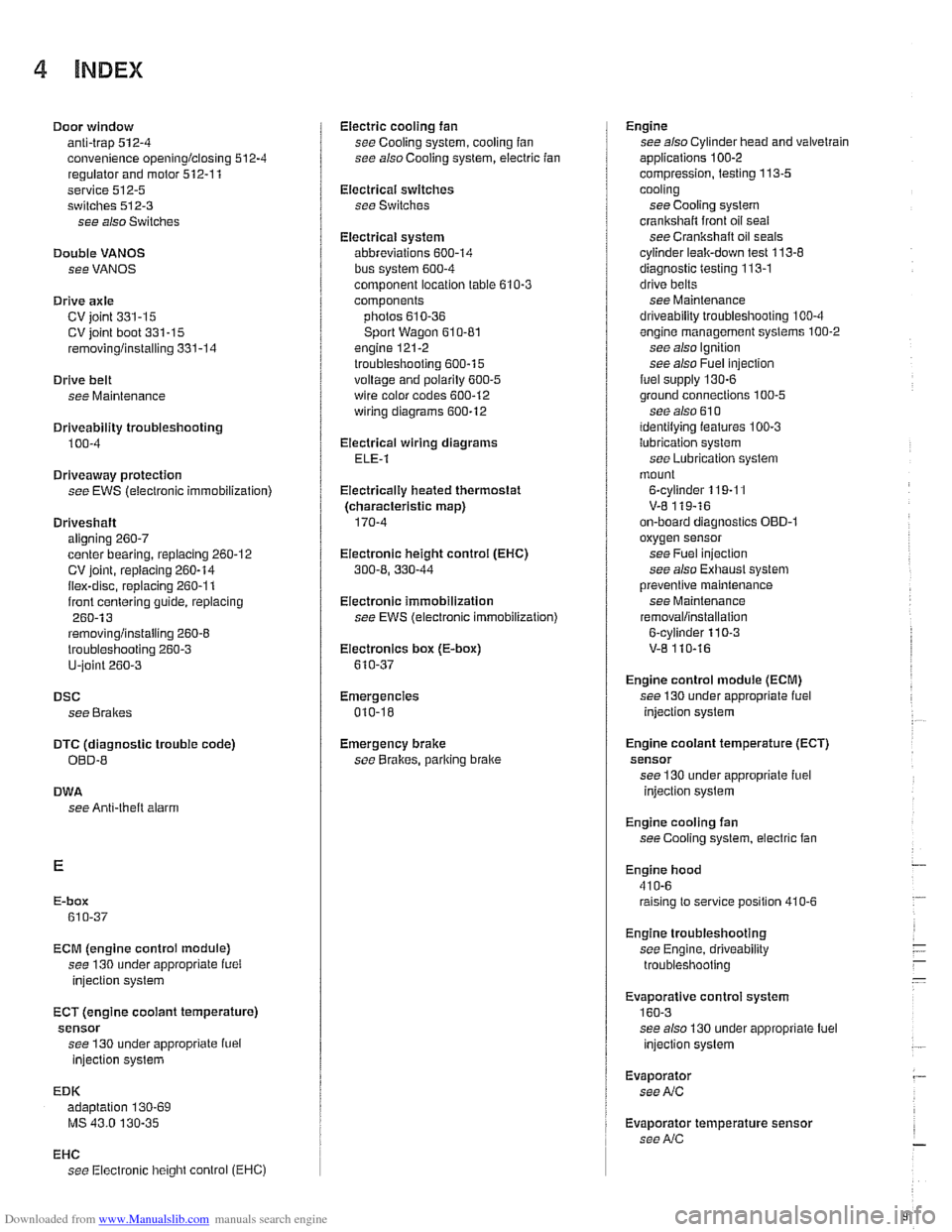
4 INDEX
Door window anti-trap
512-4 convenience openinglclosing 512.4
regulator and motor 512-1 1
service
512-5 switches 512-3
see also Switches
Double
VANOS see VANOS
Drive
axle
CV joint 331-15 CV joint boot 331-15
rernovinglinstalling 331-14
Drive belt
see Maintenance
Driveabiiity troubleshooting
100-4
Driveaway protection
see EWS (eiectronic immobilization)
Driveshaft aligning
260-7
center bearing, replacing 260-12 CV joint, replacing 260-14
itex-disc, replacing 260-1 1
iront centering guide, replacing 260-13
rernovinglinstailing 260-6
lroubleshooting 260-3
U-joint 260-3
DSC
see Braires
DTC (diagnostic trouble code)
OBD-8
DWA
see Anti-theft alarm
ECM (engine control module)
see 130 under appropriate
iuei
injection system
ECT (engine coolant temperature)
sensor see 130 under appropriate
iuei
injection system
EDK adaptation
130-69
MS 43.0 130-35
EHC see Electronic iieigiit control (EHC)
Electric cooling fan
see Cooling system, cooling
fan
see also Cooiing system, eiectric fan
Electrical switches
see Switches
Electrical system abbreviations
600-14 bus System 600-4
component location table 610-3
components
photos
610-36
Sport Wagon 610-81 engine 121-2
troubleshooting 600-15
voltage and polarily 600-5 wire color codes 600-12
wiring diagrams 600-12
Electrical wiring diagrams
ELE-1
Eiectricaliy heated thermostat
(characteristic map)
170-4
Eiectronic height control (EHC)
300-8, 330-44
Eiectronic immobilization
see EWS (electronic immobilization)
Eiectronics box
(E-box)
610-37
Emergencies
010-18
Emergency brake see
BraBes, parking brake Engine
see also Cylinder head and valvetrain
applications
100-2
compression, testing 113-5
cooling see Cooiing system
crankshaft front oil seai
see Crankshaft oil seals
cyiinder leak-down test 113-8
diagnostic testing 113-1
drive belts
see Maintenance
driveability troubleshooting
100-4
engine management systems 100-2
see also Ignition
see also Fuel injection
fuel supply
130-6
ground connections 100-5
see also 61 0 identilying ieatures 100-3
lubrication svstem
see
~ubricetion system
mount
on-board diagnostics
OBD-I
oxygensensor
see Fuel injection
see also Exhaust system
Dreventive maintenance
see Maintenance
removal/installation
Engine control module (ECM)
see 130 under appropriate iuel
injection system
Engine cooiant temperature (ECT)
sensor see 130 under appropriate iuel
injection
system
Engine cooling fan
see Cooiing system, electric fan
Engine hood
41
0-6 raising to service position 410-6
Engine troubleshooting
see Engine, driveability troubleshooting
EVa~oratiVe control svstem
160-3 see also 130 under aDDroDriate iuel
injection system
Evaporator see
NC
Evaporator temperature sensor see
NC
Page 996 of 1002
Downloaded from www.Manualslib.com manuals search engine
Gaskets and seals 01
0-9
Gearshift automatic transmission
adjusting
250-7
shift interiock. checkino function " 250-9
shiftloclc. checicino function 250-8 - manual transmission
gearshift lever, removingiinstalling
250-5
steptronic 250-7
General module (GM Ill)
600-8
see also Central locking
Generator see Battery, starter, alternator
Glass see Door window
Glove compartment
513-16
see also
Global positioning system
(GPS)
620-9
Grill
see Exterior trim
Grounds
100-5
Guide link
see Rear suspension, suspension
arms
Halogen headlight
630-5
Hand brake
see Brakes, pariring brake
Handle, door
see Door
locks
Hatch seeTailgate
Hazard warning switch
see Switches Headlight
housing trim
see Exterior trim
washer611-17 see also Lights
Headlight spray
nozzle
611-17
Headlight switch
see Switches
Heater core
see Heating
Heater valve
see Heating
Heating lieater core, replacing
640-18
lheater core temperature sensor,
removingiinstalling
640-12 heater valve, replacing 640-17
IHKA housing, removinglinstallin~
640-21
see also NC
Hood
410-6
Hood latch and release
410-10
Hydraulic valve lifters
see Cylinder head and valvetrain
IAT
(lntalce air temperature) sensor
see 130
under appropriate fuel
injection system
idle speed control valve
see 130
under appropriate fuel injection system
Idle stabilizer
see 130
under appropriate fuel
injection system, idie speed controi
valve
idler arm
320-30
lgnition coll
see lgnition system
lgnition interlock
320-13
lgnition lock cylinder
removingiinstalling
320-1 1. 612-4
lgnition switch
seeSwifches
Ignition system
diagnosis checking for
spark 120-10
disabling ignition system 120-10 misfire detection 120-6
oscilioscope diagrams 120.6
troubleshooting 120-6
camshaft position sensors 120-14 coils 120.10
crankshaft speed sensor 120-12 firing order 120-9
knoclc sensors 120-16
IHKA
see NC
IHKR see NC
Injector
see 130 under appropriate
fuel
injection system, luel injector
Input shaft
oil seal
see Manual transmission, oil seals
Inspection
see Maintenance
Instruments GPS see Global positioning system
(GPSI layout 6202
removingiinstalling 620-8 self-testing 620-6
Intake air temperature sensor (IAT)
see 130 under appropriate fuel
injection system
Intake manifold
removingiinstalling
6-cvlinder enoine 110-10. 113-8. 113-22 -
V-8 engine (M62) 113-56
Integral link
see Rear suspension, suspension
arms
lnterior lights
see Lights
lnterior protection
(FISIUIS) 515-25
lnterior trim
513-13
lnterior ventilation microfilter see
NC, ventilation microfiller
Page 999 of 1002
Downloaded from www.Manualslib.com manuals search engine
INDEX 9
WARNING
Your common sense, good judgemenl, and general alerlness are
crucial lo seie end successful service
ivork. Beiore attempting any work on
your
BMW be sure to read 001
General Warnings and Cautions and llle copyright page at lhe iron1 of
the manual. Review Niese warnings
and caulions each lime you prepare
lo work on your BMW Please also
read any warnings and caulions lllal accompany the procedures in the
manual.
Rear suspension
ball joints
330-19
bushings 330-13
control arms
seesuspension arms, below
description
300-5
electronic height control (EHC)
330-44
ride height 300-14 ride height sensor 330-46
shoclr absorbers end springs 330-9
stabilizer bar 330-42
struts and springs 330-5 subframe 330.13
suspension arms 330-13
variations 330-4 wheel bearing, replacing 330-32
see also Maintenance
see also Drive axles
see also Final drive
Rear window (Sport Wagon)
see
Tailgate
Rear window defroster 610-17
Receiverldrter
see NC
Relay positions
see Electrical component tocations
table 610-3
Remote entry (FZV)
see Central locking
Reversing light switch
see
Baclc-up light switch
Ride height
300-14
Ride height sensor
see Rear suspension
Ring antenna
see EWS (electronic immobilizalion)
Rotor
see Brakes
Roundel see Exterior trim
Running tosses
(312-way) valve
see Fuel
tenlr
SCA (soft close)
seeTailgate, soft close
see also Trunk lid. soft close
Scan tools
OED-3
Seals gaskets and 010-9
see also Crankshaft seals
Seat front,
removing/instelling 520-10
memory system 520-4 rear 520-13
see also Seat belt
Seat beit front 720-4
rear 720-8
troubleshooting 7202
see also Maintenance
Secondary air injection
see 130 under appropriate
iuel
injection system
Selector shaft seat
see Manual transmission, oil
Seals
Self-adjusting ctulch (SAC)
see Clutch, variations
Service indicator see Maintenance
Shift interlock see Gearshift
Shift lever
see
Gearshift
Shift linkage see Gearshift
Shiftlock see Gearshilt
Shack absorber see Rear suspension
/ Side turn signal assembly
see Lights
Sill trim panel
411-10
Slave cylinder
see Clutch, lhydraulic
Steep mode
600-1 1
Soft close
(SCA) see Tailgate
see also
Trunk lid
Solenoid 121-23
Sound system
650-2
Spare parts kit
010-21
Spark plugs
see Maintenance
Speakers
650-4
Specifications, fluid
020-4
Sport wagon
400-4
Springs
see Front suspension
see also Rear suspension
SRS (supplemental restraint system)
see
Airbag system (SRS)
Stabilizer bar see Front suspension
see also Rear suspension
Starter see Battery, starter, alternator