under car shield BMW 528i 2000 E39 Workshop Manual
[x] Cancel search | Manufacturer: BMW, Model Year: 2000, Model line: 528i, Model: BMW 528i 2000 E39Pages: 1002
Page 65 of 1002
Downloaded from www.Manualslib.com manuals search engine
ing at the finish when it is wet. If the water coats the paint in
smooth sheets instead of forming beads that roll off, a new
coat of wax is needed. Waxshould not be applied to black trim
pieces, rubber, or other plastic parts.
Windshield wiper blade maintenance
Common problems with the windshield wipers include streak-
ing or sheeting, water drops afler wiping, and blade chatter.
Streaking is usually caused when wiper blades are coated
with road
film or car wash wax. Clean the blades using soapy
water.
If cleaning the blades does not cure the problem, they
should be replaced. BMW recommends replacing the wiper
I blades twice a year, before and after the cold season.
I
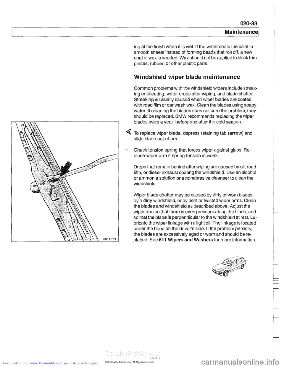
< To replace wiper blade, depress retaining tab (arrow) and
slide blade out of arm.
I - Checlc tension spring that forces wiper against glass. Re-
place wiper arm if spring tension is weak.
Drops that remain behind after wiping are caused by oil, road
film, or diesel exhaust coating the windshield. Use an alcohol
or ammonia solution or a nonabrasive cleanser to clean the
windshield.
Wiper blade chatier may be caused by dirty or worn blades,
by a dirty windshield, or by bent or twisted wiper arms. Clean
the blades and windshield as described above.
Adjusithe
wiper arm so that there is even pressure along the blade, and
so that the blade is perpendicularto the windshield at rest. Lu-
bricate the wiper linkage with a light oil. The
linkage is located
under the hood on the driver's side. If the problem persists,
the blades are excessively aged or worn and should be re-
placed. See
61 1 Wipers and Washers for more information.
Page 91 of 1002
Downloaded from www.Manualslib.com manuals search engine
110-19
Engine Removal and Installation
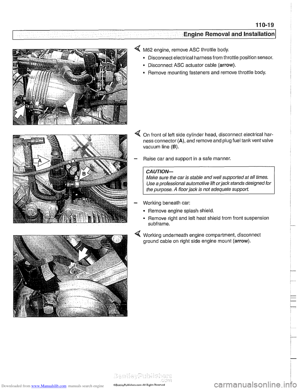
M62 engine, remove ASC throttle body.
Disconnect electrical harness from throttle position sensor.
- Disconnect ASC actuator cable (arrow).
. Remove mounting fasteners and remove throttle body.
On front of left side cylinder head, disconnect electrical har-
ness connector
(A), and remove and plug fuel tank vent valve
vacuum line
(0).
Raise car and support in a safe manner.
CAUTION-
Male sure the car is stable and well supported at aN times.
Use a professional automotive
lifi orjackstands designed for
I the ouroose. A floor jack is not adequate support.
Working beneath car:
- Remove engine splash shield.
Remove right and left heat shield from front suspension
subframe.
Working underneath engine compartment, disconnect
ground cable on right side engine mount
(arrow).
Page 330 of 1002
Downloaded from www.Manualslib.com manuals search engine
11 9-1 0
Lubrication System
Oil pan, removing and installing
(6-cylinder)
The engine oil pan removal procedure requires that the en-
gine be supported from the top and the front suspension
sub-
frame be lowered.
- Raise car and place securely on jack stands.
Make sure the car is stable and well supported at all times.
Use a professional automotive
lift orjackstands designed for
- Remove splash shield from under engine.
- Drain engine oil as described in 020 Maintenance.
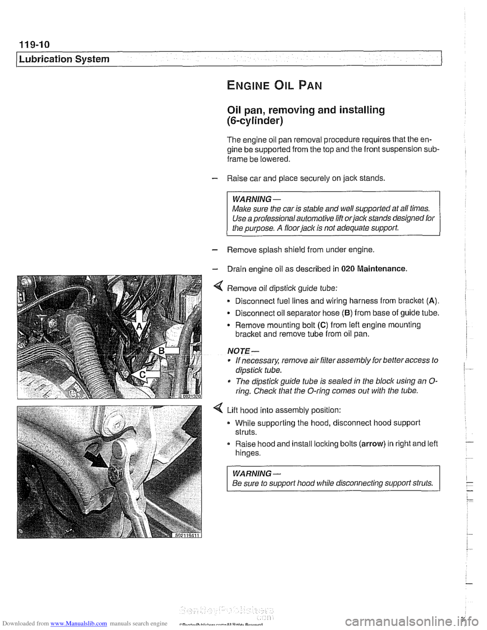
4 Remove oil dipsticlc guide tube:
Disconnect fuel lines and wiring harness from
bracket (A).
- Disconnect oil separator hose (B) from base of guide tube.
Remove mounting bolt
(C) from left engine mounting
bracket and remove tube from oil pan.
NOTE-
* If necessary, remove air filter assembly for better access to
dipsticlc tube.
The dipstick guide tube is sealed in the block using an
O-
ring. Check that the O-ring comes out with the tube.
4 Lift hood into assembly position:
While supporting the hood, disconnect hood support
struts.
Raise hood and install
loclting bolts (arrow) in right and left
hinges.
WARNING-
Be sure to support hood while disconnecting support struts.
Page 333 of 1002
![BMW 528i 2000 E39 Workshop Manual Downloaded from www.Manualslib.com manuals search engine
-- . - .. . - Lubrication system]
- Remainder of installation is reverse of removal.
Replace self-locking nuts when reinstalling front BMW 528i 2000 E39 Workshop Manual Downloaded from www.Manualslib.com manuals search engine
-- . - .. . - Lubrication system]
- Remainder of installation is reverse of removal.
Replace self-locking nuts when reinstalling front](/img/1/2822/w960_2822-332.png)
Downloaded from www.Manualslib.com manuals search engine
-- . - .. . - Lubrication system]
- Remainder of installation is reverse of removal.
Replace self-locking nuts when reinstalling front suspen-
sion components.
Use new oil dipstick tube sealing O-ring.
After adding engine oil, start and run engine. Raise engine
speed to 2,500 rpm until oil pressure warning light goes out
(about 5 seconds).
NOTE-
BMW does not specify a front end alignment following this
procedure.
Tightening torques Front subfrarne to body rail
(M12, use new bolts)
8.8 grade
10.9 grade
12.9 grade 77 Nrn
(57 ft-lb)
105 Nrn (77 ft-lb)
110 Nrn (81 ft-lb)
Stabilizer bar link to stabilizer bar
65 Nrn (48 ft-lb)
Steering shaft universal joint clamping bolt
(use new bolt)
19 Nrn (14 it-lb)
Lower oil pan, removing and installing (V-8)
- The V-8 engine is equipped with a 2-piece oil pan. The fas-
teners in
V-8 engine oil pump assembly, including the
sprocket retaining nut, are known to loosen and fall off into
the oil pan. Be sure to install these fasteners with Loctite
O
or equivalent thread locking product and torque to specifica-
tions.
CAUTION-
It is recommended that the oil pump retaining bolts and oil
pump drive sprocket retaining nut tightening torque be
checkedany time the
oilpan is removed.
- Raise car and place securely on jack stands.
WARNING-
Make sure the car is stable and well supported at all times.
Use a professional automotive lift
orjack stands designed for
- Remove splash shield from under engine.
- Drain engine oil
- On cars with automatic transmission, remove ATF cooler line
brackets from oil pan.
Page 383 of 1002
Downloaded from www.Manualslib.com manuals search engine
121-17
Bauery, Starter, Alternator
- Remove engine splash shield from underneath car.
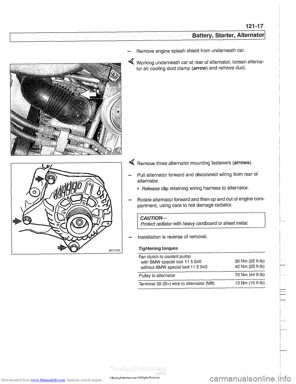
Working underneath car at rear of alternator, loosen alterna-
tor air cooling duct clamp
(arrow) and remove duct.
Remove three alternator mounting fasteners
(arrows)
Pull alternator forward and disconnect wiring from rear of
alternator.
Release clip retaining wiring harness to alternator.
Rotate alternator forward and then up and out of engine com-
partment, using care to not damage radiator.
CAUTIOe
Protect radiator with heavy cardboard or sheet metal.
Installation is reverse of removal,
Tightening
torques
Fan clutch to coolant pump
with BMW special tool
11 5 040 30
Nm (22 ft-lb)
without BMW special tool 11 5 040 40 Nm (29 ft-lb)
Pullev to alternator 70 Nm 144 it-lb) -,
Terminal 30 (Bt) wire to alternator (ME) 13 Nm 110 ft-lb
Page 386 of 1002
Downloaded from www.Manualslib.com manuals search engine
I Battery, Starter, Alternator
- Check for battery voltage at terminal 50 of starter motor with
key in start position. If voltage is not present, check wiring be-
tween ignition switch and starter terminal. Check the EWS
system and other inputs that disrupt terminal
56 to the start-
er. See ELE Electrical
Wiring Diagrams. If voltage is
present and no other visible wiring faults can be found, prob-
lem is most likely in starter motor.
Starter, removing and installing
(6-cylinder engine)
The starter is removed from below. Access to starter bolts is
difficult. Be sure to have the proper tools on hand before pro-
ceeding.
NOTE-
Access to the starter wiring is very limited. Forbetteraccess,
it may be necessary to remove the intake manifold.
- Disconnect negative (-) battery cable.
CAUTIOI\C
Prior to disconnecting the battern read the baltery discon-
nection cautions
in OOlGeneral Cautions and Warnings.
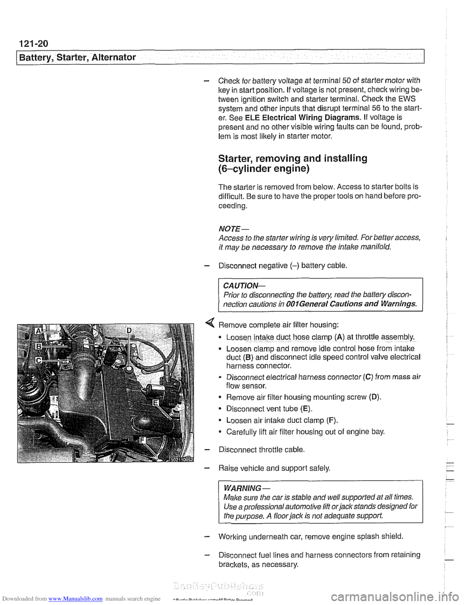
Remove complete air filter hous~ng:
Loosen intake duct hose clamp (A) at throttle assembly.
Loosen clamp and remove idle control hose from intake
duct
(B) and disconnect idle speed control valve electrical
harness connector.
Disconnect electrical harness connector
(C) from mass air
flow sensor.
Remove air filter housing mounting screw (D)
Disconnect vent tube
(E).
Loosen air intake duct clamp (F).
Carefully lift air filter housing out of engine bay.
Disconnect throttle cable.
Raise vehicle and support safely.
WARNING-
Make sure the car is stable and well supported at all times.
Use a professional automotive
lift orjack stands designed for
the purpose. A
floorjaclc is not adequate support
- Working underneath car, remove engine splash shield
- Disconnect fuel lines and harness connectors from retaining
brackets, as necessary.
Page 388 of 1002
Downloaded from www.Manualslib.com manuals search engine
-
Battery, Starter, Alternator
- Working underneath car, remove engine splash shield.
- Remove heat shield from starter.
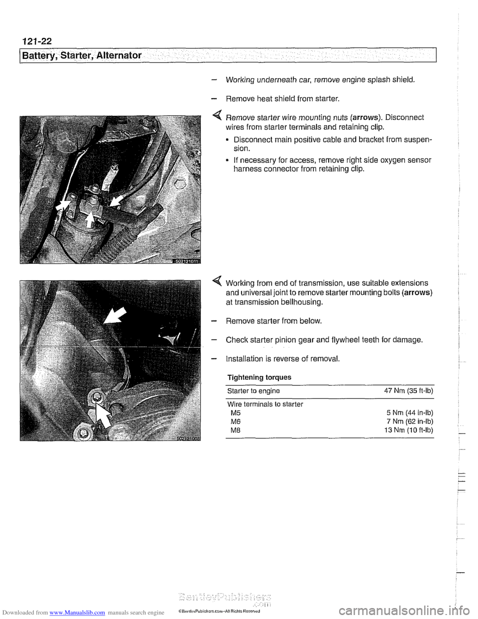
Remove starter wire mounting nuts (arrows). Disconnect
wires from starter terminals and retaining clip.
Disconnect main positive cable and bracket from suspen-
sion.
If necessary for access, remove right side oxygen sensor
harness connector from retaining clip.
Working from end of transmission, use suitable extensions
and universal joint to remove starter mounting bolts (arrows)
at transmission bellhousing.
- Remove starter from below.
- Check starter pinion gear and flywheel teeth for damage.
- Installation is reverse of removal
Tightening torques Starter
to engine 47 Nrn (35
ft-lb)
Wire terminals to starter
M5 5 Nrn (44 in-ib)
M6 7 Nm (62 in-ib)
ME 13 Nrn (10 ft-lb)
Page 492 of 1002
Downloaded from www.Manualslib.com manuals search engine
160-22
Fuel Tank and Fuel Pump
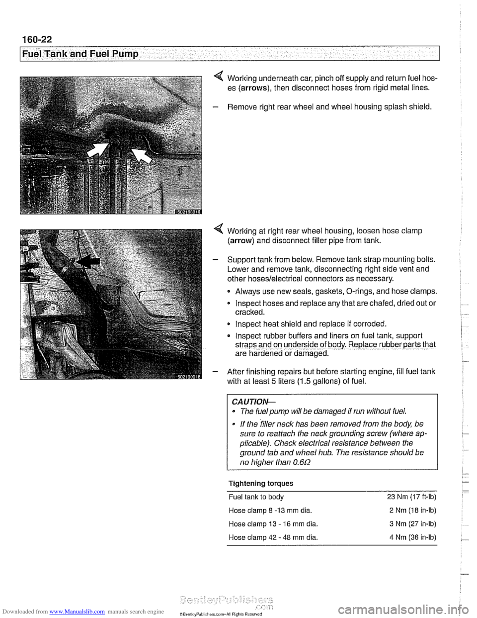
4 Working underneath car, pinch off supply and return fuel hos-
es (arrows), then disconnect hoses from rigid metal lines.
- Remove right rear wheel and wheel housing splash shield.
4 Worlting at right rear wheel housing, loosen hose clamp
(arrow) and disconnect filler pipe from tank.
- Support tank from below. Remove tank strap mounting bolts.
Lower and remove tank, disconnecting right side vent and
other
hoses/electrical connectors as necessary.
Always use new seals, gaskets, O-rings, and hose clamps.
lnspect hoses and replace any that are chafed,
dr~ed out or
cracked.
lnspect heat shield and replace if corroded.
Inspect rubber buffers and
hers on fuel tank, support
straps and on underside of body. Replace rubber parts that
are hardened or damaged.
- After finishing repairs but before starting engine, fill fuel tank
with at least
5 liters (1.5 gallons) of fuel.
CAUTlOI+
The fuelpump will be damaged if run without fuel.
* If the filler neck has been removed from the body, be
sure to reattach the
neck grounding screw (where ap-
plicable). Check electrical resistance between the
ground tab and wheel
hub. The resistance should be
no
hiaher than 0.6f2
Tightening torques
Fuel tank to body 23 Nm (17 ft-lb)
Hose clamp
8 -13 mm dia. 2 Nm (18 in-lb)
Hose clamp 13
- 16 mm dia. 3 Nm (27 in-lb)
Hose clamp 42
- 48 mm dia. 4 Nm (36 in-lb)
Page 494 of 1002
Downloaded from www.Manualslib.com manuals search engine
Fuel Tank and Fuel Pump 1
Activated carbon canister I fuel tank leak
detection unit
(LDP or DMTL), removing . . -
and installing
- Raise rear end of car and support safely.
CAUTION-
Make sure the car is stable and well supported at all times.
Use a professional automotive lift
orjack stands designed for
the purpose.
A floor jack is not adequate support.
- Remove left rear wheel and inner fender panel
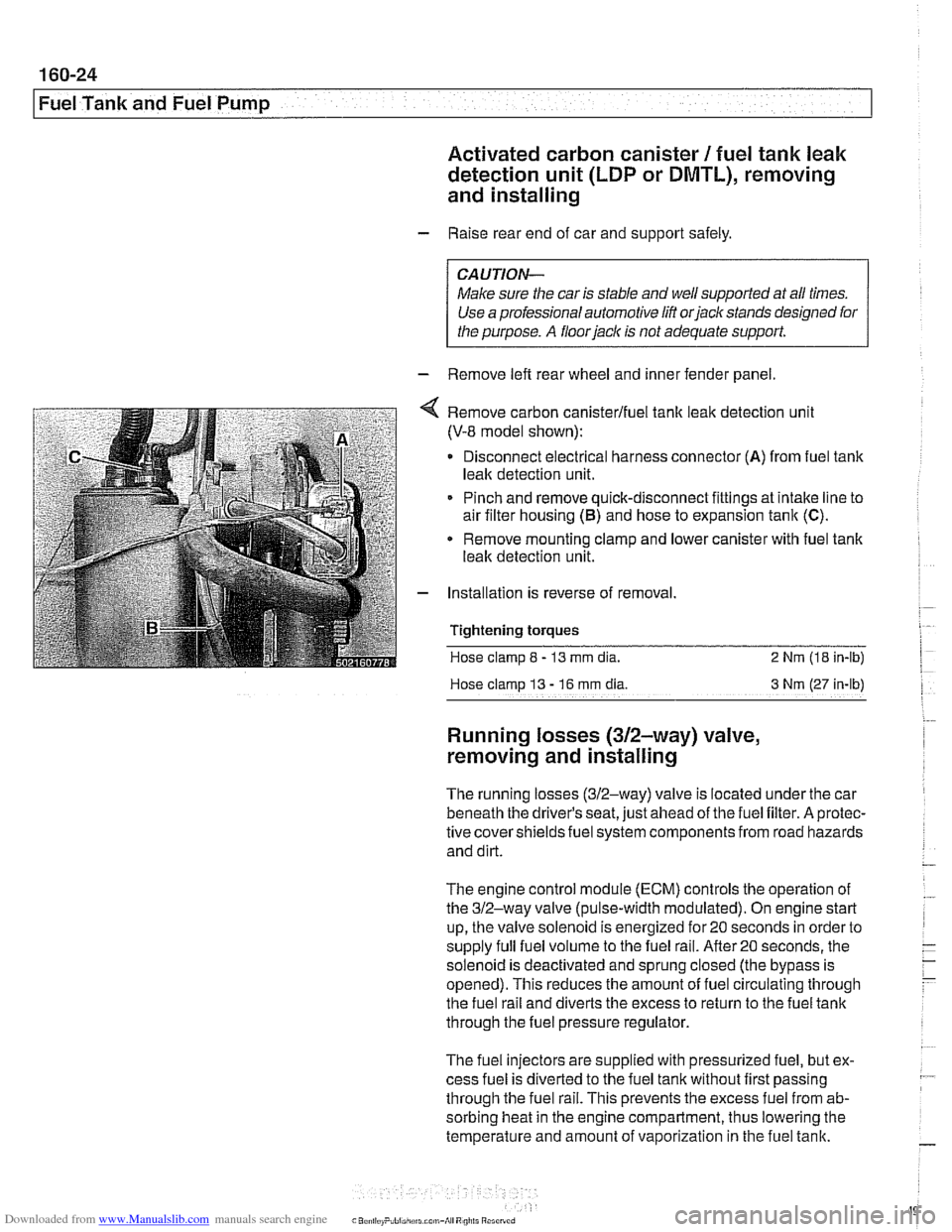
Remove carbon canisterlfuel tank leak detection unit
(V-8 model shown):
Disconnect electrical harness connector
(A) from fuel tank
leak detection unit.
Pinch and remove quick-disconnect fittings at intake line to
air filter housing
(5) and hose to expansion tank (C).
* Remove mounting clamp and lower canister with fuel tank
leak detection unit.
Installation is reverse of removal.
Tightening
torques
Hose clamp 8 - 13 mm dia. 2 Nrn (18 in-lb)
Hose clamp
13 - 16 rnm dia 3 Nm (27 in-lb)
Running losses (312-way) valve,
removing and installing
The running losses (312-way) valve is located under the car
beneath the driver's seat, just ahead of the fuel filter. A protec-
tive covershieldsfuel system components from road hazards
and dirt.
The engine control module
(ECM) controls the operation of
the 312-way valve (pulse-width modulated). On engine start
up, the valve solenoid is energized for 20 seconds in order to
supply full fuel volume to the fuel rail.
After20 seconds, the
solenoid is deactivated and sprung closed (the bypass is
opened). This reduces the amount of fuel circulating through
the fuel rail and diverts the excess to return to the fuel tank
through the fuel pressure regulator.
The fuel injectors are supplied with pressurized fuel, but ex-
cess fuel is diverted to the fuel tank without first passing
through the fuel rail. This prevents the excess fuel from ab-
sorbing heat in the engine compartment, thus lowering the
temperature and amount of vaporization in the fuel tank.
Page 506 of 1002
Downloaded from www.Manualslib.com manuals search engine
170-1 0
I Radiator and Cooling System
Combustion chamber leak test
- If you suspect that combustion chamber pressure is leaking
into the cooling system past the cylinder head gasket, use an
exhaust gas analyzer to test the vapors rising from the cool-
ant at the expansion tank.
CAUTIO&
Use an extension tube above the reservoir neclc to main-
tain distance between the top of the coolant and the gas
analyzer
nozzle. The gas analyzer is easily damaged if it is
allowed to inhale liquid coolant.
* While running engine to checlc for causes of overheat-
ing, observe coolant temperature carefully in order to
avoid engine damage.
Thermostat
If the engine overheats or runs too cool and no other cooling
system tests indicate trouble, the thermostat may be faulty.
In
V-8 models and 6-cvlinder models nroduced afler 911 998
(M52TU or M54 eng'ne), rheelecrricaily heated rhermostal IS
mon tored by [he OBD II diagnostlc software The fault may ic
in the DME software or hardware, or it may lie in the wiring to
the thermostat. See
OED On-Board Diagnostics.
Coolant, draining and filling
(6-cylinder models)
WARNING -
Allow the cooling system to cool before opening or draining
the cooling system.
- Raise front of car and support safely.
WARNING -
Make sure the car is stable and well supported at all times.
Use a professional automotive lift
orjack stands designed for
the purpose. A floor jack is not adequate support.
- Remove splash shield from under engine.
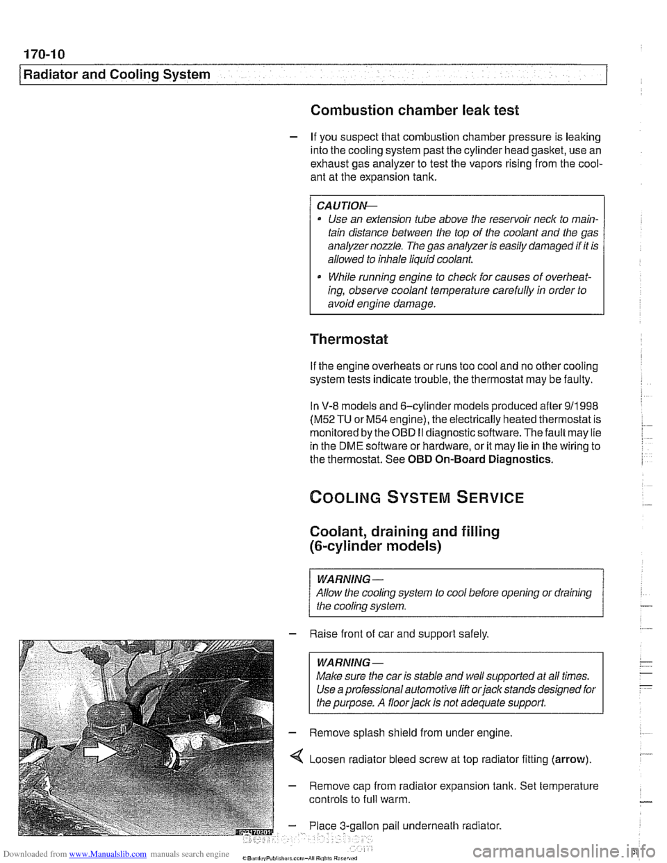
4 Loosen radiator bleed screw at top radiator fitting (arrow).
- Remove cap from radiator expansion tank. Set temperature
controls to
full warm.
gallon pail underneath radiator.