cruise control BMW 530i 1997 E39 Workshop Manual
[x] Cancel search | Manufacturer: BMW, Model Year: 1997, Model line: 530i, Model: BMW 530i 1997 E39Pages: 1002
Page 79 of 1002
Downloaded from www.Manualslib.com manuals search engine
Engine Removal and lnstallationl
NOTE-
BMW uses three styles of fuel line connections; a one-time
single use clamp, a locking fitting that uses special tool
16 1
050 to release, and a quick release sleeve (arrow) that dis-
connects the line when depressed.
WARNING-
Fuel may be expelled under pressure. Do not smoke or work
near heaters or other fire hazards. Keep a fire extinguisher
handy Before disconnecting fuel hoses, wrap a cloth around
fuel hoses to absorb any leaking fuel. Plug all
oDen fuel lines.
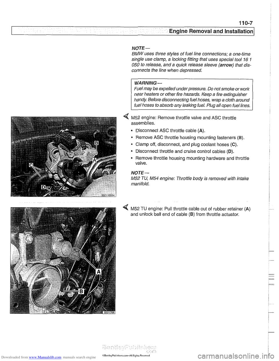
< M52 engine: Remove throttle valve and ASC throttle
assemblies.
Disconnect ASC throttle cable
(A).
Remove ASC throttle housing mounting fasteners (El).
Clamp off, disconnect, and plug coolant hoses (C).
Disconnect throttle and cruise control cables (D).
Remove throttle housing mounting hardware and throttle
valve.
NOTE-
M52 TU, M54 engine: Throttle body is removed with intake
manifold.
< M52 TU engine: Pull throttle cable out of rubber retainer (A)
and unloclc ball end of cable (6) from throttle actuator.
Page 414 of 1002
Downloaded from www.Manualslib.com manuals search engine
Fuel Injection
- Ignition:
Direct ignition
Knock control
4 Primary1 secondary ignition monitoring
- Emissions:
OBD II compliance
Secondary air injection
Pre- and post-catalyst oxygen sensors
0 Electrically heated DME-mapped thermostat
Misfire detection
Evaporative emission control and
leak detection
Malfunction indicator light (MIL)
Performance controls:
Dual VANOS control
Output of injection signal (TI) for fuel economy gauge
Output of engine rpm (TD) for tachometer
AIC compressor control
0 Electric radiator cooling fan
CAN-Bus communication
Stability and traction system
(ABSIASCIDSC) interlace
Electronic immobilizer (EWS)
Cruise control
ECM programming
Page 454 of 1002
Downloaded from www.Manualslib.com manuals search engine
-
Fuel Injection
Table e. Bosch 5.2.1 ECM pin assignments
Pin
I~iqnal 1 Description 1 Note
I I I
46 llnput ICrankshaft position sensor Icrankshaft positionlrpm sensor
38
39
40
41
42
43
44
45 Ground Input
Output
Output
Output
Output
Ground
47
48
49
50
51
Not used
I Not used
52
Shield, knock sensor
Oil level
- thermal
Injection signal
injection signal
Idle speed control - opening winding
Idle speed control - closing winding
Not used
Ground
Ground
-- Ground Input
Ground
Ground Not used Knock sensor
Oil level sensor
Cylinder
4 fuel injector
valve
Cylinder
1 fuel injector valve
Idle speed control valve
Idle speed control valve
Shield, crankshaft sensor
5
6
7
12 Not used
Ground
Intake air temperature sensor
Connector
X60004
8
9 10
11
14 1 1 Not used I
Shield, knock sensor
Shield, sensor
I
Shield, sensor 3
Shield, itnock sensor
Input
- Knoclc sensor
Knock sensor
Knock sensor
Knock sensor
Instrument cluster
Output
2 llnput l~erminal 30 voltage supply /Megrated instrument cluster control module (IKE)
Alt. charge indicator signal, terminal 61 1
Not used
Start signal terminal
50
Not used
15
16
17
18
Output
Ignition switch
Not used
Not used
Activation of relay for fuel pump
Not used
19
Fuel pump relay
Output Not used
I I I 20 loutput ICARB signal /Data link connector
Not
used
Not used
Engine speed signal output (TD)
Not used
Light module
21
Cruise control module (Tempomat)
22 llnput I Right rear wheel speed signal /ABS/ASC or ABSIDSC control module
Oulput
Washer
fluid level,
brake fluid level
Page 457 of 1002
Downloaded from www.Manualslib.com manuals search engine
130-67
Fuel Injection /
ME 7.2 system overview
The Bosch ME 7.2 system is used on 1999 - 2002 540i mod-
els.
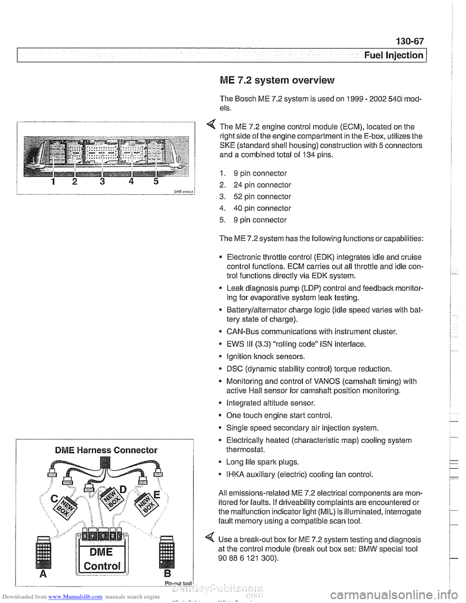
1 4 The ME 7.2 enaine control module (ECM). located on the
l and a combined total of 134 pins.
--__-- 1 I. 9 pin connector
12 3 4 5 2 24 pin connector
0lliC;nii, 3. 52 pin connector
4. 40 pin connector
5. 9 pin connector
The ME 7.2 system has the following functions or capabilities:
Electronic throttle control (EDK) integrates idle and cruise
control functions. ECM carries out all throttle and idle con-
trol functions directly via EDK system.
Leak diagnosis pump
(LDP) control and feedback monitor-
ing for evaporative system leak testing.
Batterylalternator charge logic (idle speed varies with bat-
tery state of charge).
CAN-Bus communications with instrument cluster.
EWS
111 (3.3) "rolling code" ISN interface.
Ignition
knock sensors.
DSC (dynamic stability control) torque reduction.
Monitoring and control of VANOS
(camshaft timing) with
active Hail sensor for camshaft position monitoring.
Integrated altitude sensor.
One touch engine start control
Single speed secondary air injection system.
Long life spark plugs.
IHKA auxiliary (electric) cooling fan control.
All emissions-related ME 7.2 electrical components are mon-
itored for faults. if driveability complaints are encountered or
the malfunction indicator
light (MIL) is illuminated, interrogate
fault memory using a compatible scan tool.
4 Use a break-out box for ME 7.2 system testing and diagnosis
at the control module
(break out box set: BMW special tool
90
88 6 121 300).
Electrically heated (characteristic
map) cooling system
DME Harness Connector thermostat.
Page 665 of 1002
Downloaded from www.Manualslib.com manuals search engine
320-7
Steering and Wheel ~liqnmentl
STEERING WHEEL
Steering wheel, removal and installation
WARNING -
The BMWairbag system (Supplemental Restraint System or
SRS) is complex. Special precautions must be observed
when servicing. Serious injury may result if
SRS system serv-
ice is
attempted by persons unfamiliar with the BMW SRS
and its approved service procedures. BMW specifies that all
inspection andservice should be preformed by an authorized
BMW dealer.
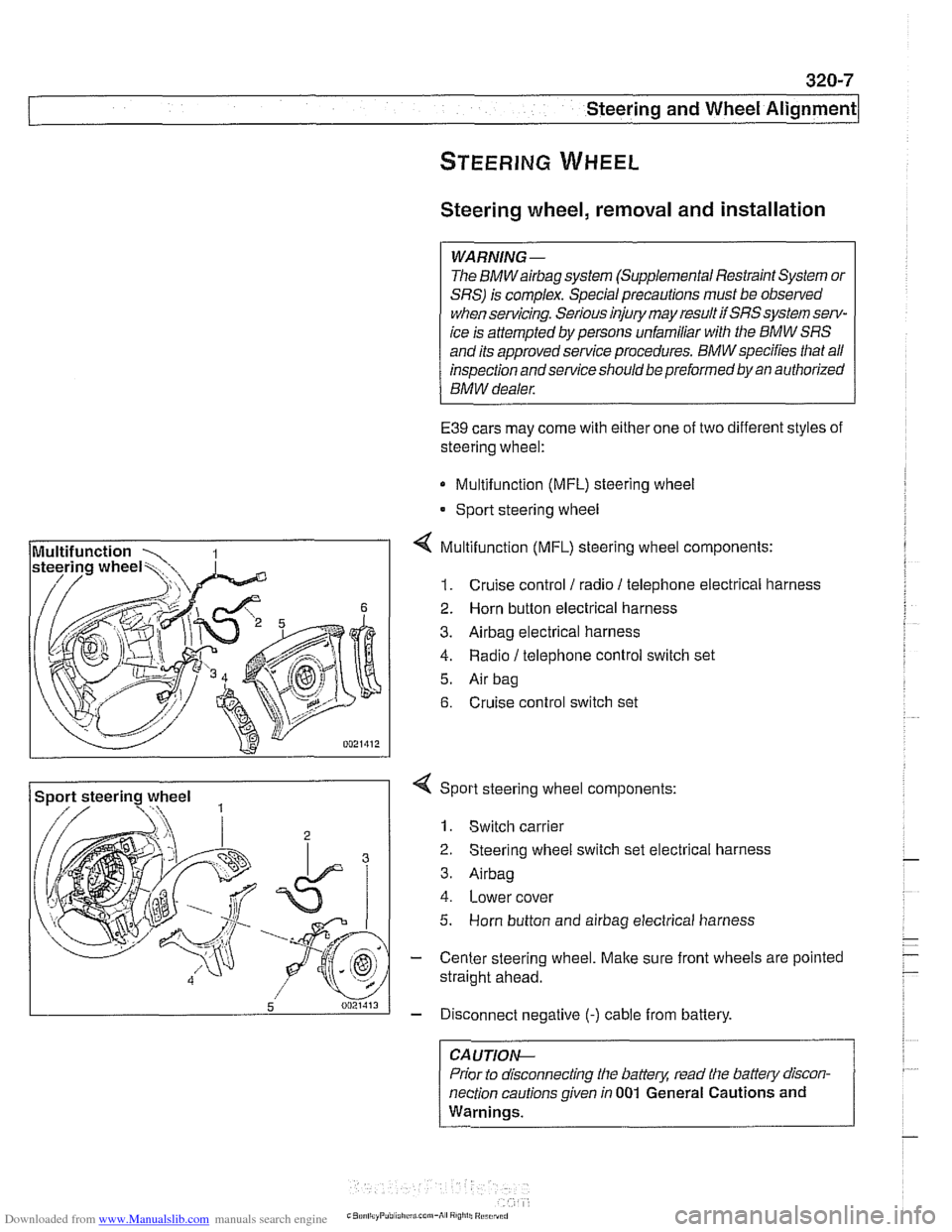
E39 cars may come with either one of two different styles of
steering wheel:
Multifunction (MFL) steering wheel
* Sport steering wheel
4 Multifunction (MFL) steering wheel components:
1. Cruise control 1 radio 1 telephone electrical harness
2. Horn button electrical harness
3. Airbag electrical harness
4. Radio / telephone control switch set
5. Air bag
6. Cruise control switch set
Sport steering wheel
3
5 0021413
4 Sport steering wheel components:
1. Switch carrier
2 Steering wheel switch set electrical harness
3. Airbag
4. Lower cover
5. Horn button and airbag electrical harness
- Center steering wheel. Make sure front wheels are pointed
straight ahead.
- Disconnect negative (-) cable from battery.
CA UTIOP&
Prior to disconnecting the battern read the battew discon-
nection cautions given in
001 General Cautions and
Warnings.
-
Page 666 of 1002
Downloaded from www.Manualslib.com manuals search engine
320-8
Steering and Wheel Alignment
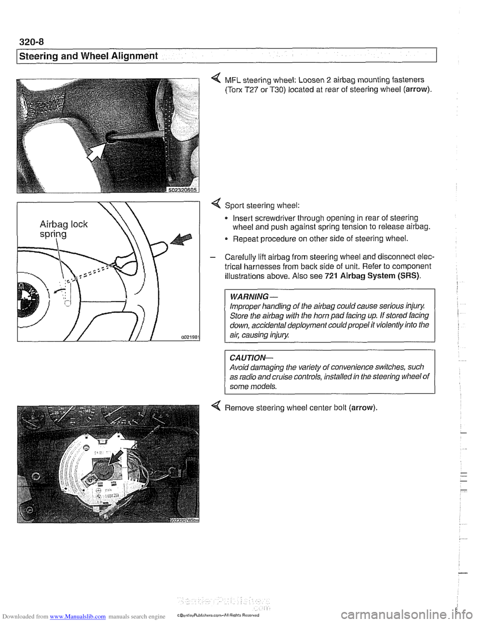
4 MFL steering wheel: Loosen 2 airbag mounting fasteners
(Torx T27 or T30) located at rear of steering wheel (arrow).
4 Sport steering wheel:
Insert screwdriver through opening in rear of steering
wheel and push against spring tension to release
airbag.
Repeat procedure on other side of steering wheel.
- Carefully lift airbag from steering wheel and disconnect elec-
trical harnesses from
back side of unit. Refer to component
illustrations above. Also see
721 Airbag System (SRS).
Improper handling of the airbag could cause serious injury.
Store the
airbag with the horn pad facing up. If stored facing
down, accidental deployment couldpropel it violently into the
Avoid damaging the variety of convenience switches, such
as radio and cruise controls, installed in the steering wheel of
4 Remove steering wheel center bolt (arrow).
Page 804 of 1002
Downloaded from www.Manualslib.com manuals search engine
400-1 0
Body-General
Seats
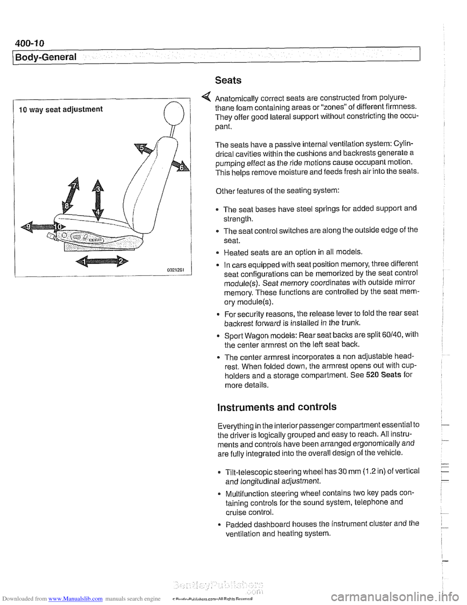
4 Anatomically correct seats are constructed from polyure-
10 way seat adjustment thane foam
containing areas or "zones" of different firmness.
They offer good lateral support without constricting the occu-
pant.
The seats have a passive internal ventilation system: Cylin-
drical cavities within the cushions and backrests generate a
pumping effect as the ride motions cause occupant motion.
This
helps remove moisture and feeds fresh air into the seats.
Other features of the seating system:
The seat bases have steel springs for added support and
strength.
The seat control switches are along the outside edge of
the
seat.
Heated seats are an option in all models
In cars equipped with seat position memory, three different
seat confiaurations can be memorized by the seat control
module(s): Seat memory coordinates with outside mirror
memory. These functions are controlled by the seat mem-
ory
module(s).
* For security reasons, the release lever to fold the rear seat
backrest forward is installed in the trunk.
Sport Wagon models: Rear seat
baclts are split 60140, with
the center armrest on the left seat back.
The center armrest incorporates a non adjustable head-
rest. When folded down, the armrest opens out with
cup-
holders and a storage compartment. See 520 Seats for
more details.
instruments and controls
Everything in the interior passengercompartment essential to
the driver is logically grouped and easy to reach. All instru-
ments and controls have been arranged ergonomically and
are fully integrated into the overall design of the vehicle.
Tilt-telescopic steering wheel has
30 mm (1.2 in) of vertical
and longitudinal adjustment.
Multifunction steering wheel contains two
ltey pads con-
taining controls for the sound system, telephone and
cruise control.
Padded dashboard houses the instrument cluster and the
ventilation and heating system.
Page 993 of 1002
Downloaded from www.Manualslib.com manuals search engine
WARNING
Your common sense, good
judgement, and general alertness are
crucial lo sale and
successlul service
work. Belore attempling any work on
your BMW, be sure to read 001
General Warnings and Cautions
and lhe copyright page
a1 llle Iron1 01
the manual. Review lliese warnings
and cautions each time you prepare
lo work on your
BMW Please also
read any warnings and
caulions lhal
accompany the procedures In !he
manual.
Component locations
see Electrical system
Compression test
113-5
Compressor see
AlC
Condenser see
AlC
Constant velocity (CV) joint
see Maintenance
see also
Driveshall
see also Drive axles
Consumer cutoff
600-10
Control arm see Front suspension
see also Rear suspension,
suspension arms
Coolant (antifreeze) see Maintenance
see also Cooling system
Coolant pump
see Cooling system Cooling system
coolant bleeding
170-14 6-cylinder engine, draininglfilling
170-10
V-8 engine, draininglfilling 170-12
coolant pump 170-3
6-cyiinder engine, replacing 170-1 9
V-8 engine, replacing 170-20 cooling fan 170-4
viscous ciutch fan, removingi
installing 170-14
electric fan, removlngiinstailing 170-1 5
expansion tank, removinglinstalling
170-22
electrically heated (ciiaracterislic
map) therrnostat 170-4
radiator, removinglinstaliing 170-22
service
see Maintenance
therrnostat 170-16
transmission fluid heat exchanger
170-5 troubleshooting 170-7
combuslion leal( test 170-10
pressure test
170-9
Crankshaft oil seals
iront
117-6
rear 11 9-6
Crankshaft speed sensor
see Ignition syslem
Crash sensor
see
Airbag system (SRS), side-impact
airbag crasii sensor
Cruise control clutch switch 612-9
CV joint
see Maintenance
see also Driveshalt
see also Drive axles
CV joint boot
see Maintenance
see also Drive axles
Cylinder head removinglinslaliing
M52 engine 113-8
M52 TU / M54 engine 113-22
M62 engine 113-56
Cylinder head and valvetrain
hydraulic lifters, checking and
replacing
116-7 leak test 116-5 valves 11 6-56
see
alsocylinder head Dashboard
513-7
Deck
lid
seeTrunk lid
Diagnostic monitors
OED-4
Diagnostic trouble codes
(DTCs)
080-7
Digital multimetel
010-17
Differential see Final drive
DLC (data
link connector) 020-4, OED-4
DME (digital motor electronics)
see
130 under appropriate fuel
injection system
see also ignition system
DM-TL (detection module-tank leak)
see
Fuel lank, leak deteclion unit
Drive
belts
see Maintenance
Dome light
seeLighls, interior lights
Door
door
check, replacing 411-4
hinge adjustment 41 1-5
loci(
see Door lock see also Central locking
removinglinslaliing 41
1-2
panel, removinglinstaliing 41 1-7 window
see Door window
Door
check
see Door
Door
handle
see Door lock
Door glass
see Door window
Door
lock
handles and loci(s 515-16
see also Central locking
Door
molding
510-13
Door panel see Door