Ecu BMW 530i 2000 E39 Repair Manual
[x] Cancel search | Manufacturer: BMW, Model Year: 2000, Model line: 530i, Model: BMW 530i 2000 E39Pages: 1002
Page 804 of 1002
Downloaded from www.Manualslib.com manuals search engine
400-1 0
Body-General
Seats
4 Anatomically correct seats are constructed from polyure-
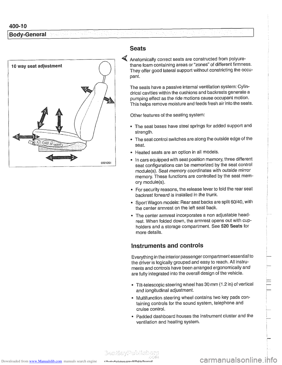
10 way seat adjustment thane foam
containing areas or "zones" of different firmness.
They offer good lateral support without constricting the occu-
pant.
The seats have a passive internal ventilation system: Cylin-
drical cavities within the cushions and backrests generate a
pumping effect as the ride motions cause occupant motion.
This
helps remove moisture and feeds fresh air into the seats.
Other features of the seating system:
The seat bases have steel springs for added support and
strength.
The seat control switches are along the outside edge of
the
seat.
Heated seats are an option in all models
In cars equipped with seat position memory, three different
seat confiaurations can be memorized by the seat control
module(s): Seat memory coordinates with outside mirror
memory. These functions are controlled by the seat mem-
ory
module(s).
* For security reasons, the release lever to fold the rear seat
backrest forward is installed in the trunk.
Sport Wagon models: Rear seat
baclts are split 60140, with
the center armrest on the left seat back.
The center armrest incorporates a non adjustable head-
rest. When folded down, the armrest opens out with
cup-
holders and a storage compartment. See 520 Seats for
more details.
instruments and controls
Everything in the interior passengercompartment essential to
the driver is logically grouped and easy to reach. All instru-
ments and controls have been arranged ergonomically and
are fully integrated into the overall design of the vehicle.
Tilt-telescopic steering wheel has
30 mm (1.2 in) of vertical
and longitudinal adjustment.
Multifunction steering wheel contains two
ltey pads con-
taining controls for the sound system, telephone and
cruise control.
Padded dashboard houses the instrument cluster and the
ventilation and heating system.
Page 810 of 1002
Downloaded from www.Manualslib.com manuals search engine
41 0-4
Fenders, Engine Hood
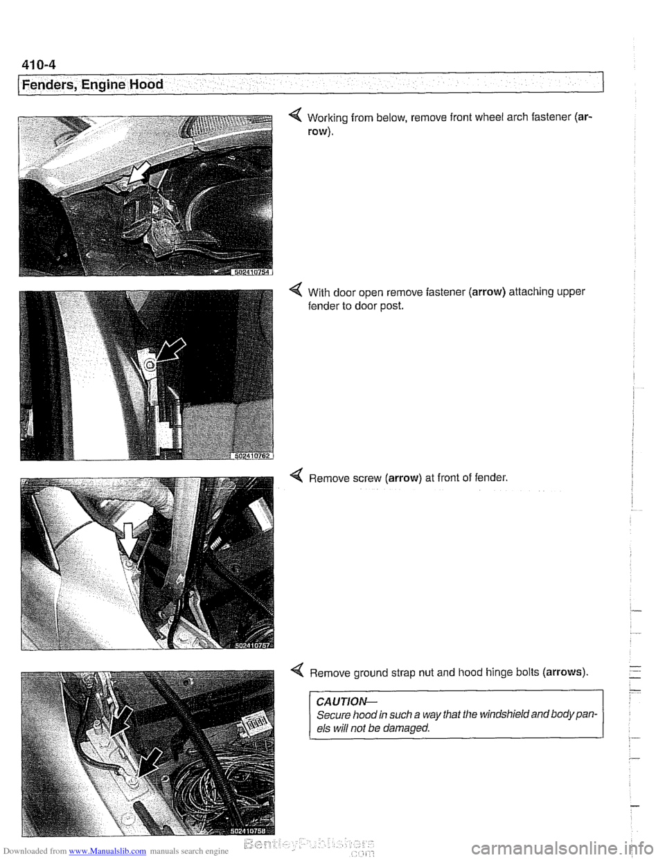
Working from below, remove front wheel arch fastener (ar-
row).
With door open remove fastener
fender to door post. (arrow) attaching upper
Remove screw
(arrow) at front of fender.
Remove ground strap nut and hood hinge bolts
(arrows)
CAUTION-
Secure hood in such a way that the windshield and body pan-
els
wiN not be damaged.
Page 864 of 1002
Downloaded from www.Manualslib.com manuals search engine
Exterior Trim, Bumpers 1
Radiator grill, removing and installing
- Open hood
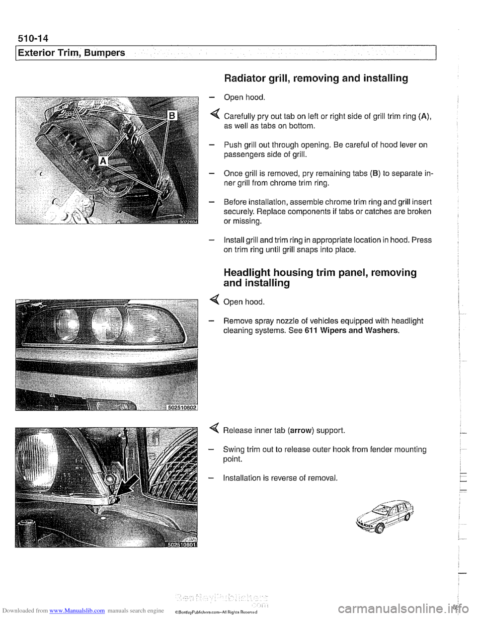
4 Carefully pry out tab on lefl or right side of grill trim ring (A),
as well as tabs on bottom.
- Push grill out through opening. Be careful of hood lever on
passengers side of grill.
- Once grill is removed, pry remaining tabs (B) to separate in-
ner grill from chrome trim ring.
- Before installation, assemble chrome trim ring and grill insert
securely. Replace components
if tabs or catches are brolten
or missing.
- Install grill and trim ring in appropriate location in hood. Press
on trim ring until grill snaps into place.
Headlight housing trim panel, removing
and installing
4 Open hood
- Remove spray nozzle of vehicles equipped with headlight
cleaning systems. See
611 Wipers and Washers.
Release inner tab (arrow) support.
Swing trim out to release outer hook
point. from fender mounting
Installation is reverse of removal
Page 905 of 1002
Downloaded from www.Manualslib.com manuals search engine
515-11
Central Lockinq and ~nti-l heft/
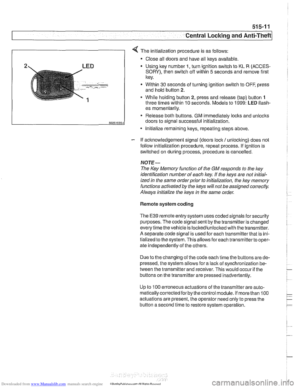
4 The initialization procedure is as follows:
Close ail doors and have all keys available
2 LED Using lkey number I, turn ignition switch to KL R (ACCES-
SORY), then switch off within 5 seconds and remove first
key.
. - -- , ..-.---- - Within 30 seconds of turning ignition switch to OFF, press
and hold button
2.
1 While holding button 2, press and release (tap) button 1
three times within 10 seconds. Models to 1999: LED flash-
- If acknowledgement signal (doors lock / unlocking) does not
follow initialization procedure, repeat process. If ignition is
switched on during process, procedure is cancelled.
50251509‘1
NOTE-
The Key Memory function of the GM responds to the ley
identification number of each key If the keys are not initial-
ized
in the same orderprior to initialization, the ley memory
functions activated by the
l(eys will not be assigned correctly.
Always initialize the keys
in the same order.
es momentarily.
Release both buttons. GM immediately locks and unlocits
doors to signal successful initialization.
Remote system coding
* Initialize remaining lteys, repeating steps above.
The E39 remote entry system uses coded signals for security
purposes. The code signal sent by the transmitter is changed
every time the vehicle is lockedlunlocked with the transmitter.
A separate code signal is used for each transmitter that is ini-
tialized to the system. This allows for each transmitterto oper-
ate independently of the others.
Due to the changing of the code each time the buttons are de-
pressed, the system allows for a
lacit of synchronization be-
tween the transmitter and receiver. This would occur
if the
buttons on the transmitter are pressed inadvertently.
Up to
100 erroneous actuations of the transmitter are auto-
matically corrected
forby the control module. If more than 100
actuations are present, the operator need only to press the
button a second time to restore system operation.
Page 961 of 1002
Downloaded from www.Manualslib.com manuals search engine
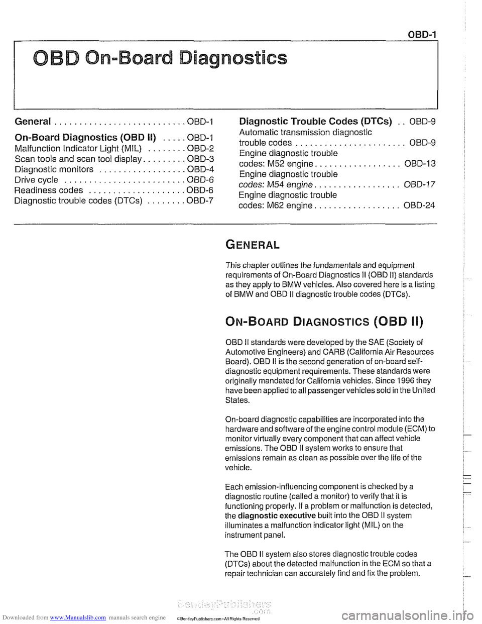
OBD On-Board Diagnostics
I I
General ........................... OBD-1 Diaqnostic Trouble Codes (DTCs) . . OBD-9
On-Board Diagnostics (OBD I!) ..... OBD-I
Malfunction Indicator Light (MIL)
........ OBD-2
Scan tools and scan tool display.
........ OBD-3
Diagnostic monitors
.................. OED-4
Drive cycle
......................... OED-6
Readiness codes
.................... OBD-6
Diagnostic trouble codes
(DTCs) ........ OBD-7
-
Automatic transmission diagnostic
trouble codes
....................... OBD-9
Engine diagnostic trouble
codes: M52 engine.
................. OED-13
Engine diagnostic trouble
codes: M54 engine.
................. OBD-17
Engine diagnostic trouble
codes: M62 engine.
................. OBD-24
This chapter outlines the fundamentals and equipment
requirements of On-Board Diagnostics
I1 (OBD 11) standards
as they apply to BMW vehicles. Also covered here is a listing
of BMW and OBD
I1 diagnostic trouble codes (DTCs).
ON-BOARD DIAGNOSTICS (QBD !I)
OBD II standards were developed by the SAE (Society of
Automotive Engineers) and CARB (California Air Resources
Board).
OED I1 is the second generation of on-board self-
diagnostic equipment requirements. These standards were
originally mandated for California vehicles. Since
1996 they
have been applied
toall passengervehicles sold in the United
States.
On-board diagnostic capabilities are incorporated into the
hardware and soflwareof the enginecontrol module
(ECM) to
monitor virtually every component that can affect vehicle
emissions. The
OED I1 system works to ensure that
emissions remain as clean as possible over the life of the
vehicle.
Each emission-influencing component is checked by a
diagnostic routine (called a monitor) to verify that it is
functioning properly.
If a problem or malfunction is detected,
the
diagnostic executive built into the OBD I1 system
illuminates a malfunction indicator light (MIL) on the
instrument panel.
The OBD
I1 system also stores diagnostic trouble codes
(DTCs) about the detected malfunction in the ECM so that a
repair technician can accurately find and fix the problem.
Page 962 of 1002
Downloaded from www.Manualslib.com manuals search engine
OED-2
On-Board Diagnostics
Specialized OED II scan tool equipment is needed to access
the fault memory and
OED I1 data.
The extra hardware needed to operate the OED
I1 system
consists mainly of the following:
* Additional oxygen sensors downstream of the catalytic
converters.
Fuel tank pressure sensor and device to pressurize
fuel
storage system.
Several engine and performance monitoring devices
Standardized 16-pin
OED II connector under the
dashboard.
Upgraded components for the federally required reliability
mandate.
Malfunction indicator light (MIL)
OED II software illuminates the malfunction indicator light
(MIL) when emission levels exceed 1.5 times Federal
standards.
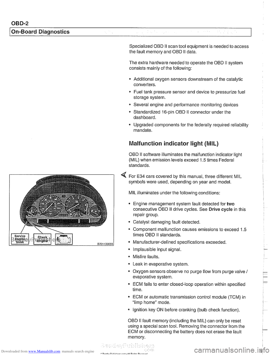
4 For E34 cars covered by this manual, three different MIL
symbols were used, depending on year and model.
MIL illuminates under the following conditions:
Engine management system fault detected for
two
consecutive OED iI drive cycles. See Drive cycle in this
repair group.
- Catalyst damaging fault detected.
Component malfunction causes emissions to exceed 1.5
times OED
II standards.
Manufacturer-defined specifications exceeded. Implausible input signal.
Misfire
faults.
Leak in evaporative system,
Oxygen sensors observe no purge
flow from purge valve 1
evaporative system.
ECM fails to enter closed-loop operation within specified
time.
ECM or automatic transmission control
module (TCM) in
"limp home" mode.
ignition key ON before cranking (bulb
check function).
OED
II fault memory (including the MIL) can only be reset
using a special scan tool. Removing the connector from the
ECM or disconnecting the battery does not erase the fault
memory.
Page 963 of 1002
Downloaded from www.Manualslib.com manuals search engine
OBD-3
On-Board
~iactnosticsl
Additional MIL information:
A fault code is stored within the ECM upon the first
occurrence of a fault in the system being checlted.
Two complete consecutive drive cycles with the iault
present illuminate the MIL. The exception to the two-fault
requirement is a catalyst-damaging fault, which illuminates
the MIL immediately.
If the second drive cycle was not complete and the fault
was not checked, the ECM counts the third drive cycle as
the next consecutive drive cycle. The MIL illuminates
if the
system is checked and the fault is still present.
Once the MIL is illuminated, it remains illuminated until the
vehicle completes three consecutive drive cycles without
detecting a fault.
0 An existing fault code is cleared from memory
automatically when the vehicle completes
40 consecutive
drive cycles without the fault being detected.
In order to automatically clear a catalyst-damaging fault from
memory, the condition underwhich the fault occurred must be
evaluated for 80 consecutive drive cycles without the fault
reoccurring.
A generic scan tool connected to the BMW data link
connector (DLC) or OBD
I1 plug can display diagnostic trouble
codes (DTCs), along with the conditions associated with the
illumination of the MIL. Using a more advanced or
BMW-
dedicated scan tool, additional proprietary information is
normally available.
Scan tool and scan tool display
The complexity of the OBD I1 system requires that all
diagnostics begin by connecting a scan tool to the vehicle.
Aftermarltet scan tools can be connected to either the 16-pin
OBD
I1 plug or the 20-pin BMW DLC in the engine
compartment
(ii installed). Data from the OBD II plug may be
limited, depending on scan tool and vehicle.
OBD
I1 standards reouire that the 16-oin OBD I1 oluo be
located within three
(3) feet of the driier and not're&ire any
tools to access.
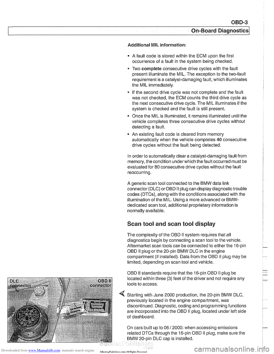
Starting with June 2000 production, the 20-pin BMW DLC,
previously located in the engine compartment, was
discontinued. Diagnostic, coding and programming functions
are incorporated into the OBD
II plug, located under left side
of dashboard.
On cars built up to 06
/ 2000: when accessing emissions
related DTCs through the 16-pin OBD
I1 plug, malte sure the
BMW 20-oin DLC
caD is installed.
Page 965 of 1002
Downloaded from www.Manualslib.com manuals search engine
On-Board Diagnostics
Catalyst monitoring. Thisstrategy monitors the outputofthe
precatalyst and post-catalyst oxygen sensors, comparing the
oxygen content going into the catalytic converter to the
oxygen leaving the converter.
The diagnostic executive
lknows that most of the oxygen
should be used up during the oxidation phase. If it detects
higherthan programmed values, afault is set and the MIL
illuminates.
Misfire detection. This strategy monitors crankshaft speed
fluctuations and determines if an enoine misfire occurs bv
monitoring variations in speed between each crankshaft
sensortrigger point. This strategy is so finely tuned that it can
determine the severity of the misfire.
The system determines
if a misfire is occurring, as well as
other pertinent misfire
information such as:
Specific
cylinder(s)
Severity of the misfire event
Emissions relevant or catalyst damaging
Misfire detection is an on-going monitoring process that is
only disabled under certain limited conditions.
Secondary air injection monitoring. Secondary air
injection is used to reduce HC and CO emissions during
engine warm up. Immediately following a cold engine start
(-1 0" to 40°C), fresh air (and therefore oxygen) is pumped
directly into the exhaust
manifold. By injecting additional
oxygen into the exhaust manifold, catalyst warm-up time is
reduced.
Secondary air system components are:
Electric air injection pump
* Electric pump relay
* Non-return valve
Vacuum
I vent valve
- Stainless steel air injection pipes
Vacuum reservoir
The secondary air system is monitored via the use
of the pre-
catalyst oxygen sensors. Once the air pump is active and air
is injected into the system, the signal at the oxygen sensor
reflects a lean condition. If the oxygen sensor signal does not
change, a fault is set and the faulty
bank(s) identified. If after
completing the next cold startafault is again present, the MIL
illuminates.
Page 992 of 1002
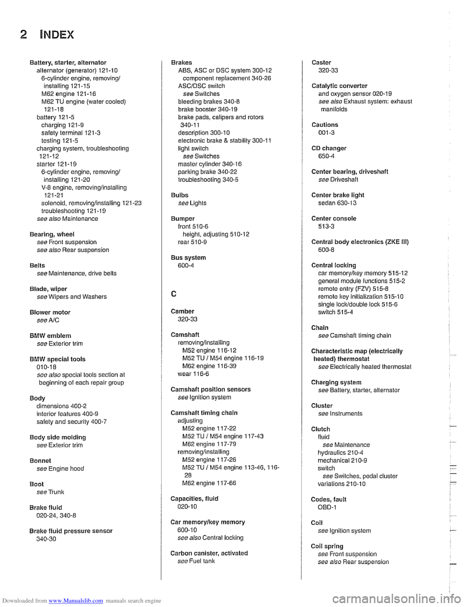
Downloaded from www.Manualslib.com manuals search engine
2 INDEX
Battery, starter, alternator
alternator (generator)
121-10
6-cylinder engine, removingi
installing 121-15
M62 engine 121-16
M62 TU engine (water cooled)
121-18
battery
121-5 charging 121-9
safety terminal 121-3
testing 121-5 charging system, troubleshooting
121-12
starter
121-1 9
6-cylinder engine, removingi instaliinq 121-20 . V-8 engine, rernovinglinsialiing
121-21
solenoid, removinglinstalling
121-23 troubleshooting 121-19
see also Maintenance
Bearing, wheel
see Front suspension
see also Rear suspension
Belts see Maintenance, drive belts
Blade, wiper
see Wipers and Washers
Blower motor see
A/C
BMW emblem
see Exterior trim
BMW special tools 010-18 see also special tools section at
beginning
of each repair group
Body dimensions 400-2
interior features
400-9 salety and security 400-7
Body side molding
see Exterior trim
Bonnet see Engine hood
Boot see Trunk
Brake fluid
020-24, 340-8
Brake fluid pressure sensor
340-30
Brakes
ABS, ASC or DSC system
300-12
component replacement 340-26
ASCIDSC switch
see Switches
bleeding
bralces 340-8
brake booster 340-1 9 bralce Dads. caiioers and rotors ,., 340-1 1
descriotion 300-10
e~ectrdnic brake & stability 300-11
light switch
see Switches
master cylinder
340-16 pariking brake 340-22
troubleshooting 340-5
Bulbs see Lights
Bumper
lront 510-6 height, adjusting 510-12
rear 510-9
Bus system
600-4
Camber
320-33
Camshaft
removingiinslaiiing
M52 engine 116-12
M52 TU
/ M54 engine 116-1 9 M62 engine 11 6-39
wear
116-6
Camshaft position sensors
see ignition system
Camshaft timing chain
adjusting M52 engine
117-22
M52 TU I M54 engine 117-43
M62 engine 117-79 removinglinstalling
M52 engine 117-26
M52TU 1 M54 engine 113-46.116-
28
M62 engine 117-66
Capacities, fluid
020.10
Car rnemorvlicev memorv . . 600-10
see also Centrai
lociking
Carbon canister, activated
see Fuel
tank
Caster
320-33
Catalytic converter and oxygen sensor 020-19
see also Exhaust system: exhaust
manilolds
Cautions
001-3
CD changer
650-4
Center bearing, driveshaft
see Driveshait
Center brake light
sedan
630-13
Center console
513-3
Centrai body electronics (ZKE 111)
600-6
Central locking
car memoryiey memory 515.12 general module iunctions 515-2
remote entry (FZV) 515-8
remote lkey initialization 515-10 single lociddouble ioclk 515-6
switch 515-4
Chain
see Camshaft liming chain
Characteristic map (electrically heated) thermostat
see Electrically heated thermostat
Charging system
see Battery, starter, alternator
Cluster see instruments
Clutch fluid see Maintenance
hydraulics
210-4
mechanical 210-9
switch
see Switches, pedal ciuster
variations
210.10
Codes, fault OED-1
Coil
see Ignition system
Coil spring
see Front suspension
see also Rear
suspe nsion