Ecu BMW 530i 2000 E39 Repair Manual
[x] Cancel search | Manufacturer: BMW, Model Year: 2000, Model line: 530i, Model: BMW 530i 2000 E39Pages: 1002
Page 594 of 1002
Downloaded from www.Manualslib.com manuals search engine
240-1 0
Automatic Transmission
TRANSMISSION REMOVAL AND
INSTALLATION
Removal and installation of the transmission is best accorn-
plished on an automotive lift using a transmission jack. Use
caution and safe workshop practices when working beneath
car and lowering transmission.
Torx-head bolts are used to mount the transmission to the
bellhousing.
Besure to have appropriate tools on hand before
starting the job.
WARNING-
Be sure the vehicle is properly supported. The removal of the
transmission may upset the balance of the vehicle on a lift
CAUJION-
Tilting the engine to remove the transmission can lead to
damaae to various components due to
laclc of clearance. 1
Transmission, removing and installing
WARNING -
Allow engine and transmission to cool down before starting
work on the transmission.
- Disconnect negative (-) cable from battery.
CAUTION-
Prior to disconnecting the battery, read the battery discon-
nection cautions given in
001 General Cautions and
Warninas.
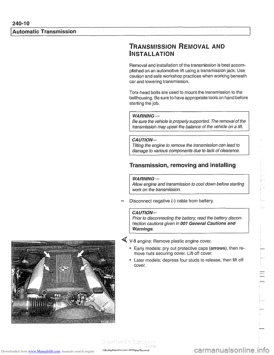
4 V-8 engine: Remove plastic engine cover.
Early models: pry out protective caps
(arrows), then re-
move nuts securing cover.
Lift off cover.
Later models: depress four studs to release, then lift off
cover.
Page 614 of 1002
Downloaded from www.Manualslib.com manuals search engine
-.- .
/ Driveshaft Driveshaft, removing
CAUTION-
. Be sure the wheels are off the ground before removing the
driveshak Set the parl(ing brake before removing the
driveshaft.
Once the driveshaft has been removed, the vehicle can
roll regardless of whether the transmission is in gear or
not.
The driveshaft is mounted to the transmission and final
drive
with self-locliing nuts. These nuts are designed to
be used only once and should be replaced during reas-
sembly.
Remove complete exhaust system. See
180 Exhaust
System.
- Remove exhaust heat shields.
- Support transmission with transmission jack.
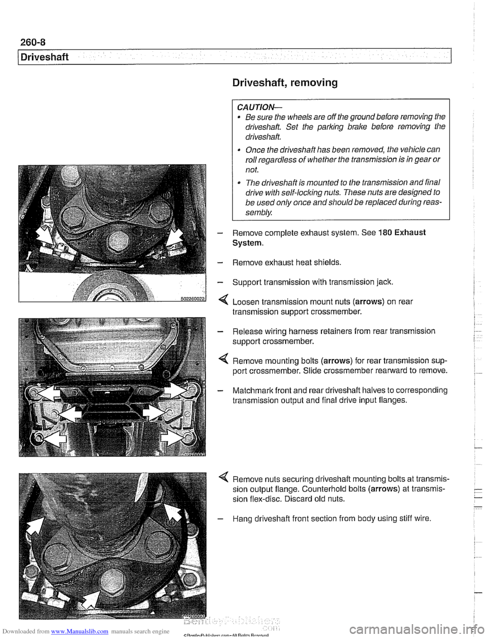
< Loosen transmission mount nuts (arrows) on real
transmission support crossmember.
- Release wiring harness retainers from rear transmission
support crossmember.
< Remove mounting bolts (arrows) for rear transmission sup-
port crossmember. Slide crossmember rearward to remove.
- Matchmark front and rear driveshaft halves to corresponding
transmission output and final drive input flanges.
4 Remove nuts securing driveshaft mounting bolts at transmis-
sion output flange. Counterhold bolts (arrows) at transmis-
sion flex-disc. Discard old nuts.
- Hang driveshaft front section from body using stiff wire.
Page 618 of 1002
Downloaded from www.Manualslib.com manuals search engine
260-1 2
1 Driveshaft
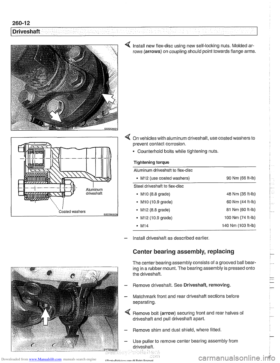
Install new flex-disc using new self-locking nuts. Molded ar-
rows (arrows) on coupling should point towards flange arms.
4 On vehicles with aluminum driveshaft, use coated washers to
prevent contact corrosion.
- Counterhold bolts while tightening nuts.
Tightening torque
Aluminum driveshaft to flex-disc
M12 (use coated washers) 90
Nm (66 ft-lb)
Steel driveshaft to flex-disc
MI0 (8.8 grade) 48
Nm (35 ft-lb)
- MI0 (10.9 grade) 60 Nm (44 ft-lb)
Coated washers - MI2 (8.8 grade) 5027500 . Mi2 (10.9 grade)
M14 81
Nm (60 ft-lb) 100 Nm (74 ft-lb)
140 Nm (103 ft-lb)
- Install driveshaft as described earlier
Center bearing assembly, replacing
The center bearing assembly consists of a grooved ball bear-
ing in a rubber mount. The bearing assembly is pressed
the driveshaft.
- Remove driveshaft. See Driveshaft, removing
- Matchmark front and rear driveshaft sections before
separating.
Remove bolt (arrow) securing front and rear halves of
driveshaft and pull driveshaft apart.
- Remove shim and dust shield, where fitted
- Use puller to remove center bearing assembly from
driveshaft. onto
Page 619 of 1002
Downloaded from www.Manualslib.com manuals search engine
- On installation, drive new center bearing firmly to stop.
Reassemble driveshaft using matchmarks made prior to
disassembly.
- Clean threads and install bolt securing driveshaft halves.
Use thread locking compound
LoctiteO or equivalent.
Tightening torque Driveshaft front half to rear half
(use thread locking compound) 97
Nm (72 fl-lb)
- Install driveshaft as described earlier.
Front centering guide, replacing
The front centering guide centers the driveshafl in relation to
the transmission. The guide is press-fit into a cavity in the
front of the driveshafl and slides onto the transmission output
shaft.
No specifications are given
forwear of the guide, but general-
ly the guide should fit snugly on the transmission output shafl.
NOTE-
Some driveshafts have a dust cap installed on the end of the
driveshaft, over the centering guide. The dust cap may be-
come bent or distorted when the driveshaft is removed or
in-
stalled. Damage to the dust cap should not affect the
centering guide and should not be mistaken for guide wear.
- Remove driveshafl as described earlier
- Pack cavity behind centering guide with heavy grease until
grease is flush with bottom edge of guide.
- Insert 14 mm (approximately 9/16 in.) diameter mandrel or
metal rod into guide. Strike guide with hammer to force cen-
tering guide out.
NOTE-
Tlie mandrel should fit snugly in the centering guide so that
the grease cannot escape around the sides of the mandrel.
- Remove old grease from driveshaft, lubricate new centering
guide with molybdenum disulfide grease
(MolykoteO, Long-
term8 2 or equivalent) and drive it into driveshaft.
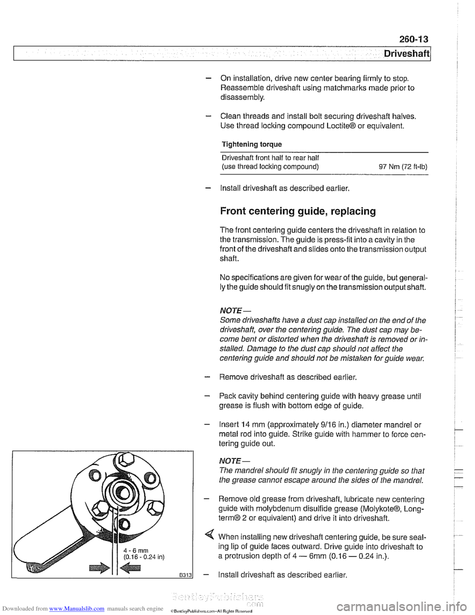
4 When installing new driveshafl centering guide, be sure seal-
ing lip of guide faces outward. Drive guide into driveshaft to
a protrusion depth of
4 - 6mm (0.16 - 0.24 in.).
- Install driveshaft as described earlier.
Page 641 of 1002
Downloaded from www.Manualslib.com manuals search engine
31 0-5
Front ~uspensionl
Front strut assembly, removing and
installing
- Raise car and remove front wheel.
WARNING-
Make sure that the car is firmly supported on jack stands de-
signed for the purpose. Place jack stands underneath struc-
tural chassis points.
Do not place jack stands under
suspension
parts.
- Unbolt bralte caliper assembly, lkeeping bralte hose connect-
ed. Secure brake caliper to body with wire. Do not let it hang
from brake hose. See
340 Brakes.
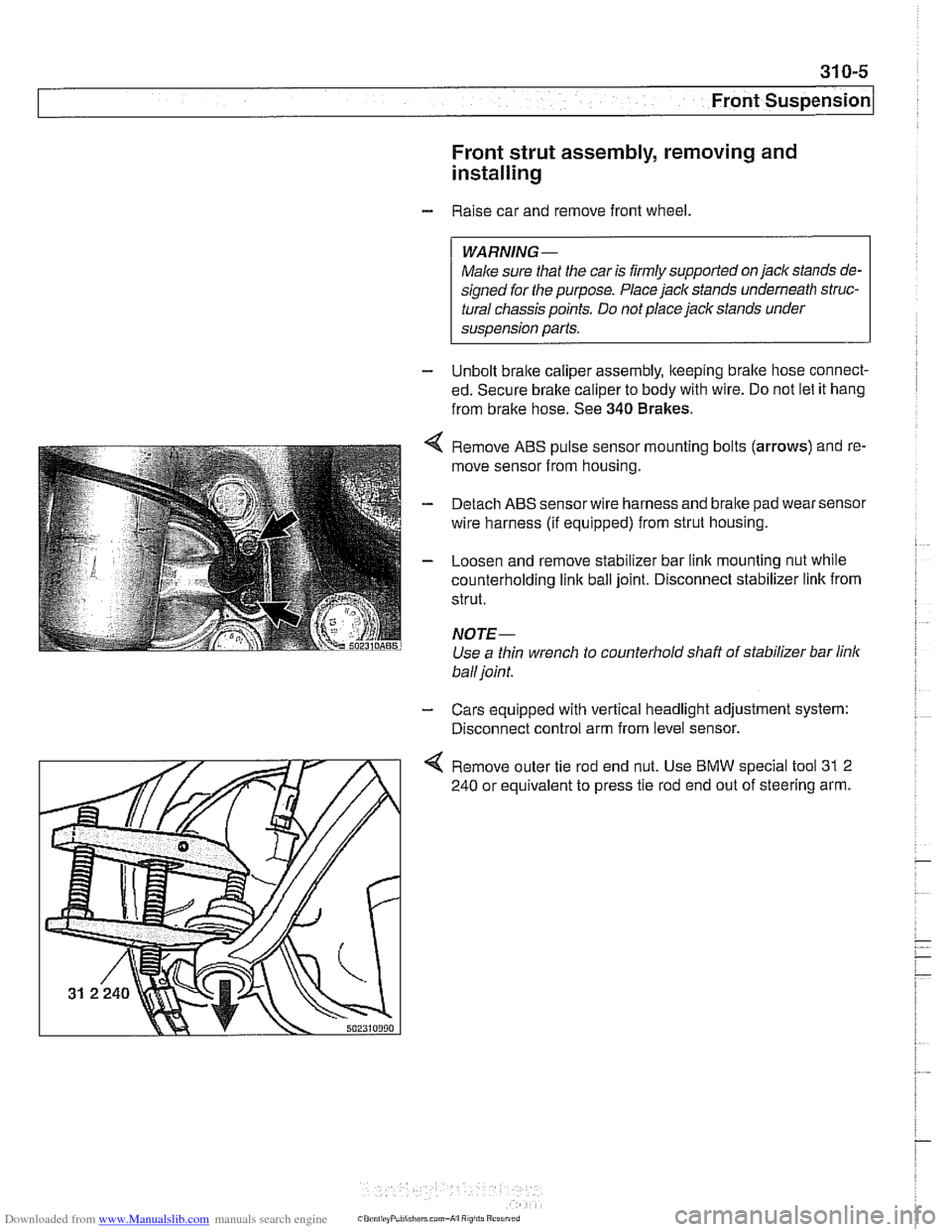
Remove ABS pulse sensor mounting bolts (arrows) and re-
move sensor from housing.
Detach ABS sensor wire harness and bralte pad wear sensor
wire harness (if equipped) from strut housing.
Loosen and remove stabilizer bar link mounting nut while
counterholding
link ball joint. Disconnect stabilizer link from
strut.
NOTE-
Use a thin wrench to counterhold shaft of stabilizer bar link
ball joint.
- Cars equipped with vertical headlight adjustment system:
Disconnect control arm from level sensor.
4 Remove outer tie rod end nut. Use BMW special tool 31 2
240 or equivalent to press tie rod end out of steering arm.
Page 779 of 1002
Downloaded from www.Manualslib.com manuals search engine
Brakes
Master cylinder, removing and installing
CAUTlOI\C
Brake fluid is highly corrosive and dangerous to the environ-
ment. Dispose of it properly.
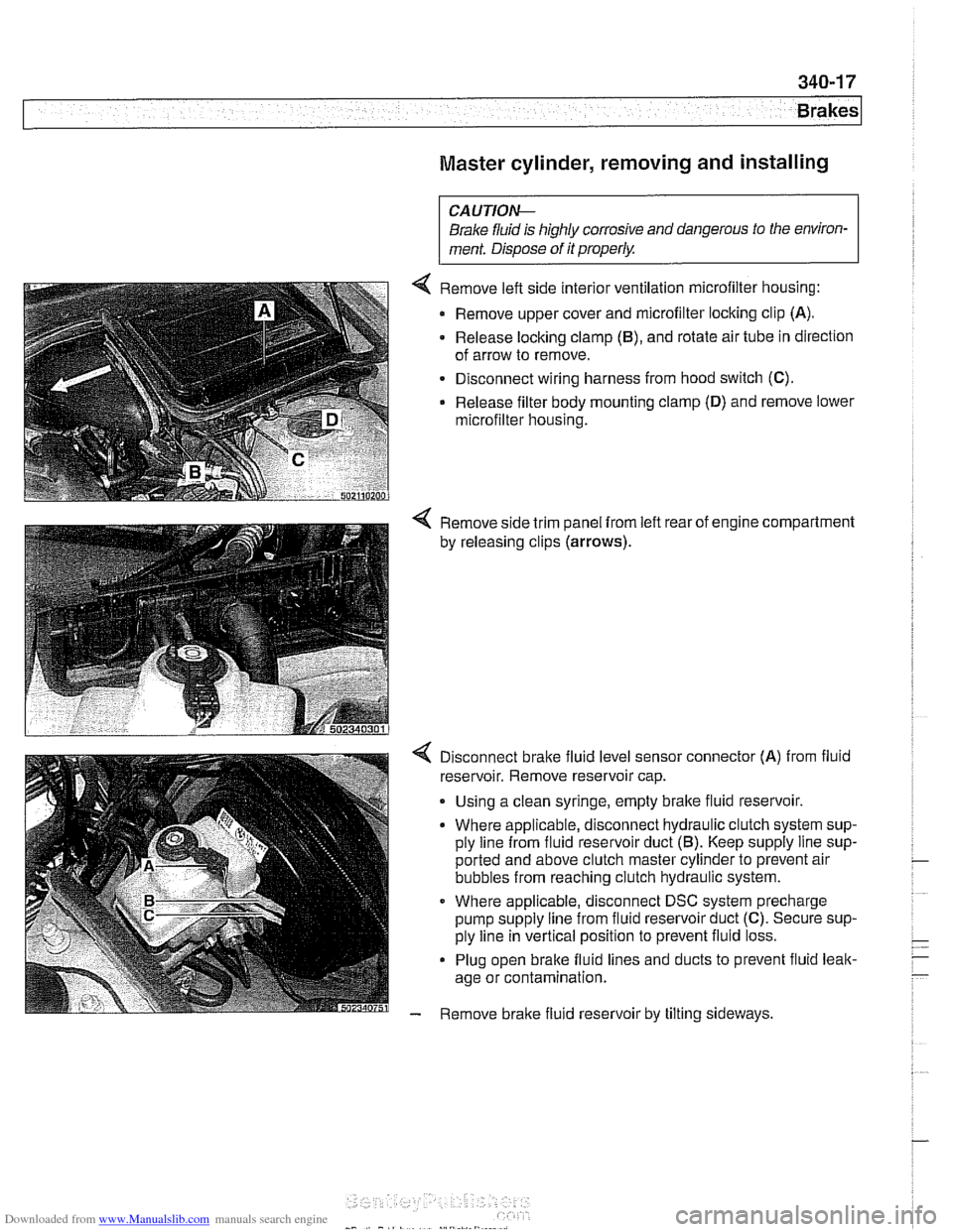
4 Remove left side interior ventilation microfilter housing:
Remove upper cover and microfilter locking clip
(A).
- Release locking clamp (B), and rotate air tube in direction
of arrow to remove.
Disconnect wiring harness from hood switch
(C).
Release filter body mounting clamp (D) and remove lower
microfilter housing.
4 Remove side trim panel from left rear of engine compartment
by releasing clips
(arrows).
4 Disconnect bralte fluid level sensor connector (A) from fluid
reservoir. Remove reservoir cap.
. Using a clean syringe, empty bralte fluid reservoir.
Where applicable, disconnect hydraulic clutch system sup-
ply line from fluid reservoir duct
(5). Keep supply line sup-
ported and above clutch master cylinder to prevent air
bubbles from reaching clutch hydraulic system.
Where applicable, disconnect DSC system precharge
pump supply line from fluid reservoir duct
(C). Secure sup-
ply line in vertical position to prevent fluid loss.
Plug open brake fluid lines and ducts to prevent fluid leak-
age or contamination.
- Remove brake fluid reservoir by tilting sideways.
Page 794 of 1002
Downloaded from www.Manualslib.com manuals search engine
340-32
Brakes
The procedure for removing the ABS I ASC or ABS I DSC hy-
draulic unit is similar for all models. The unit is located at the
right rear of the engine compartment.
- Using a clean syringe, empty brake fluid reservoir.
CAUTION-
Brake fluid is highly corrosive and dangerous to the environ-
ment. Dispose of it
properiw
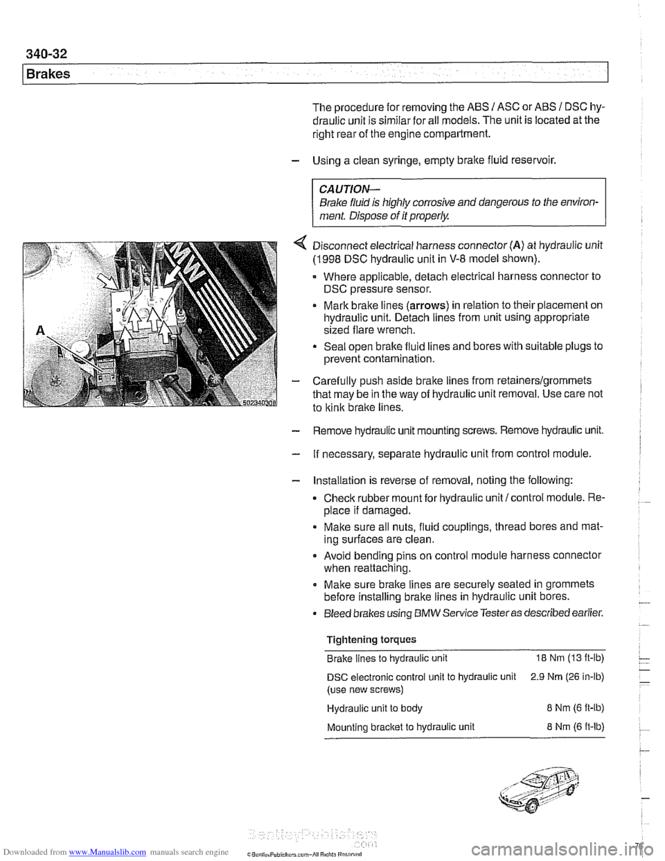
4 Disconnect electrical harness connector (A) at hydraulic unit
(1998 DSC hydraulic unit in V-8 model shown).
Where applicable, detach electrical harness connector to
DSC pressure sensor.
Mark brake lines
(arrows) in relation to their placement on
hydraulic unit. Detach lines from unit using appropriate
sized flare wrench.
Seal open brake fluid lines and bores with suitable plugs to
prevent contamination.
- Carefully push aside brake lines from retainerslgrommets
that may be in the way of hydraulic unit removal. Use care not
to
kink brake lines.
- Remove hydraulic unit mounting screws. Remove hydraulic unit.
- If necessary, separate hydraulic unit from control module.
- Installation is reverse of removal, noting the following:
Check rubber mount for hydraulic unit/control module. Re-
place if damaged.
Make sure all nuts, fluid couplings, thread bores and mat-
ing surfaces are clean.
Avoid bending pins on control module harness connector
when reattaching.
Make sure brake lines are securely seated in grommets
before installing brake lines in hydraulic unit bores.
Bleed brakes using
BMW Service Testeras described earlier.
Tightening torques Brake lines to hydraulic unit
18 Nm (13 ft-lb)
DSC electronic control unit to hydraulic unit 2.9 Nrn (26 in-lb)
(use new screws)
Hydraulic unit to body
8 Nm (6 ft-ib)
Mounting bracket to hydraulic unit 8 Nrn (6 ft-lb)
Page 795 of 1002
Downloaded from www.Manualslib.com manuals search engine
400 Body-General
........................ General ........................... .40 0.2 Roof paddin~ 400-7
Body Assembly ................... .40 0.2
Body dimensions (in inches)
............ .40 0.2
Bodyshell
........................... 400-3
Exterior and aerodynamics
............. .40 0.3
Sport Wagon ...................... .40 0.4
Tailgate
............................ .40 0.5
Tailgate lock system
.................. .40 0.5
Rear wiper system ................... .40 0.6
Antenna and sound system ............ .40 0.6
Safety and Security Features ....... .40 0.7
Safety cage
......................... .40 0.7
Door locks and door handles
........... .40 0.7
.
........................... Seat belts 400-7
Airbags ............................ 400-8
Battery safety terminal (BST)
........... 400-9
Security
............................ 400-9
Interior Features ................... 400-9
............................. Seats 400-10
Instruments and controls .............. 400-10
Central body electronics
.............. 400-1 1
Heating and Air
Conditioning (IHKA)
............... 400-12
Page 801 of 1002
Downloaded from www.Manualslib.com manuals search engine
Body-General
SAFETY AND SECURITY FEATURES
A number of new or improved safety and security features are
incorporated in
E39 cars.
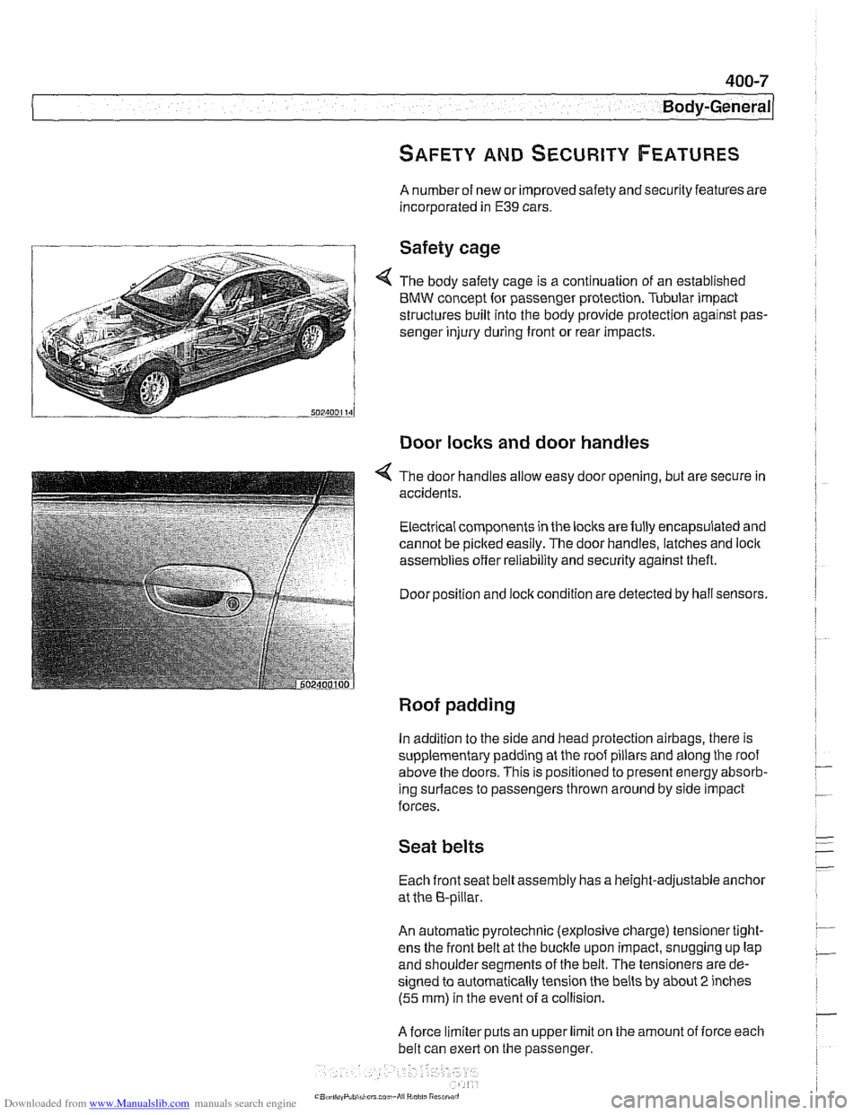
Safety cage
4 The body safety cage is a continuation of an established
BMW concept for passenger protection. Tubular impact
structures built into the body provide protection against pas-
senger injury during front or rear impacts.
Door locks and door handles
4 The door handles allow easy door opening, but are secure in
accidents.
Electrical components in the locks are fully encapsulated and
cannot be picked easily. The door handles, latches and
loclc
assemblies offer reliability and security against theft.
Door position and
loclc condition are detected by hall sensors.
Roof padding
In addition to the side and head protection airbags, there is
supplementary padding at the roof pillars and along the roof
above the doors. This is positioned to present energy absorb-
ing
surlaces to passengers thrown around by side impact
forces.
Seat belts
Each front seat belt assembly has a height-adjustable anchor
at the 8-pillar.
An automatic pyrotechnic (explosive charge) tensioner tight-
ens the front belt at the buckle upon impact, snugging up lap
and shoulder segments of the belt. The tensioners are de-
signed to automatically tension the belts by about
2 inches
(55 mm) in the event ofa collision.
A force limiter puts an upper limit on the amount of iorce each
belt can exert on the passenger.
Page 803 of 1002
Downloaded from www.Manualslib.com manuals search engine
400-9
Body-General
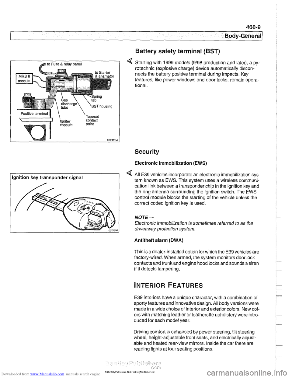
Battery safety terminal
(BST)
4 Starting with 1999 models (9198 production and later), a py-
rotechnic (explosive charge) device automatically discon-
nects the battery positive terminal during impacts. Key
features,
like power windows and door locks, remain opera-
tional.
Security
Electronic immobilization (EWS)
Ignition key transponder signal All
E39 vehicles incorporate an electronic immobilization sys-
tem known as EWS. This svstem uses a wireless comrnuni-
cation link between a transponder chip in the ignition key and
the ring antenna surrounding the ignition switch. The EWS
control module blocks the starting of the vehicle unless the
correct coded ignition key is used.
NOTE-
Electronic immobilization is sometimes referred to as the
driveaway protection system.
Antitheft alarm (DWA)
This is adealer-installed option for which the E39 vehicles are
factory-wired. When armed, the system monitors door
loci(
contacts and trunk and engine hood locks and sounds a siren
if it detects tampering.
E39 interiors have a unique character, with a combination
of
sporty features and innovativedesign. All body versions were
made in a wide choice of interior and exterior colors. New col-
ors with matching leather or leatherette upholstery were intro-
duced for each model year.
Driving
comfort is enhanced by power steering, tilt steering
wheel, height-adjustable front seats, and electrically adjust-
able and heated rear-view mirrors. Inside the car there are
reading lights at four seating positions.