engine cel BMW 530i 2001 E39 User Guide
[x] Cancel search | Manufacturer: BMW, Model Year: 2001, Model line: 530i, Model: BMW 530i 2001 E39Pages: 1002
Page 234 of 1002
Downloaded from www.Manualslib.com manuals search engine
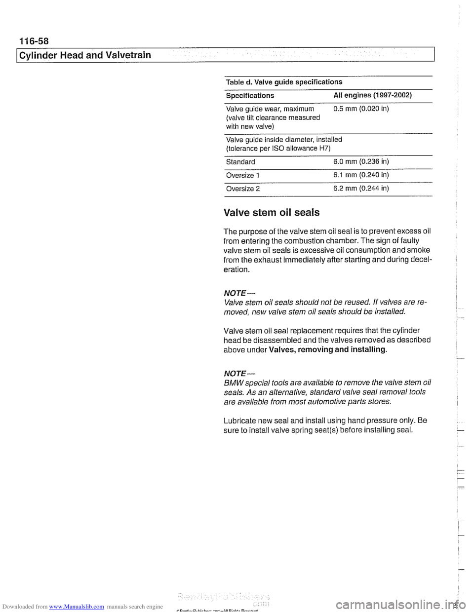
Table d. Valve guide specifications
Specifications
All engines (1997-2002)
Valve guide wear, maximum 0.5 mrn (0.020 in)
(valve tilt clearance
measured
with new valve)
Valve guide inside diameter,
installed
(tolerance per IS0 allowance H7)
Standard 6.0 mm (0.236 in)
Oversize
1 6.1 mrn (0.240 in)
Oversize 2 6.2
mm (0.244 in)
Valve stem oil seals
The purpose of the valve stem oil seal is to prevent excess oil
from entering the combustion chamber. The sign of faulty
valve stem oil seals is excessive oil consumption and smoke
from the exhaust immediately after starting and during decel-
eration.
NOTE-
Valve stem oil seals should not be reused. If valves are re-
moved, new valve stem oil seals should be installed.
Valve stem oil seal replacement requires that the cylinder
head be disassembled and the valves removed as described
above under Valves, removing and installing.
NOTE-
BMW special tools are available to remove the valve stem oil
seals. As an alternative, standard valve seal removal tools
are available from most automotive parts stores.
Lubricate new seal and install using hand pressure only. Be
sure to install valve spring
seat(s) before installing seal.
Page 357 of 1002
Downloaded from www.Manualslib.com manuals search engine
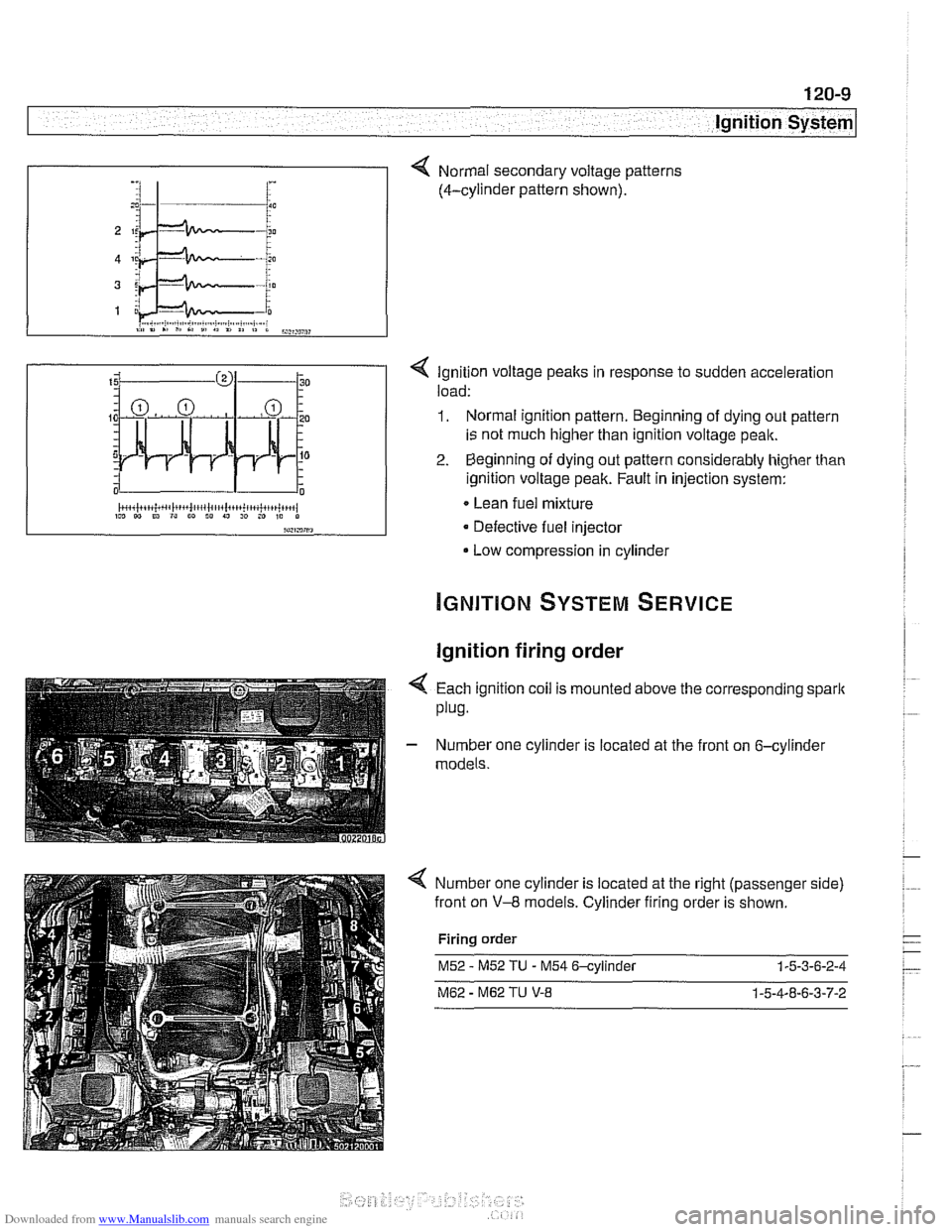
< Ignition voltage peaks in response to sudden acceleration
load:
1. Normal ignition pattern. Beginning of dying out pattern
is not much higher than ignition voltage peak.
2. Beginning of dying out pattern considerably higher than
ignition voltage peak. Fault in injection system:
Lean fuel mixture
Defective fuel injector
Low compression in cylinder
-, :I 1- i :
Ignition firing order
Normal secondary voltage patterns
(4-cylinder pattern shown).
4 Each ignition coil is mounted above the corresponding spark
plug.
- Number one cylinder is located at the front on 6-cylinder
models.
Number one cylinder is located at the right (passenger side)
front on
V-8 models. Cylinder firing order is shown.
Firing order
M52 - M52 TU - M54 6-cylinder 1-5-3-6-2-4
M62 - M62 TU V-8 1-5-4-8-6-3-7-2
Page 372 of 1002
Downloaded from www.Manualslib.com manuals search engine
.
Battery, Starter, Alternator
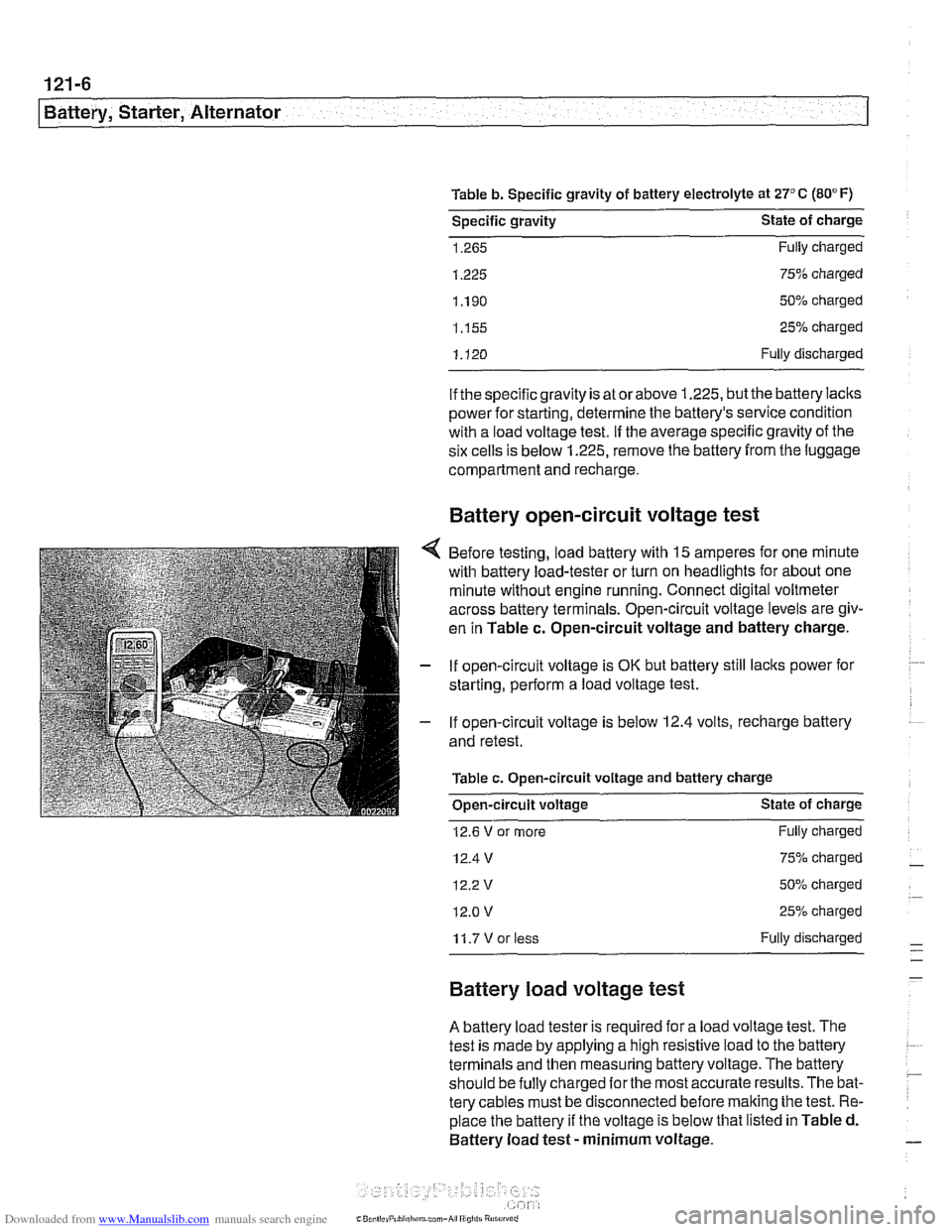
Table b. Specific gravity of battery electrolyte at 27°C (80°F)
Specific gravity State of charge
1.265 Fully charged
1.225 75% charged
1.190 50% charged
1.155 25% charged
1.120 Fully discharged
if the specific gravity is at
orabove 1.225, butthe battery lacks
Dower for
startinq, determine the battew's service condition
with a load volta& test. if the average specific gravity of the
six cells is below 1.225, remove the battery from the luggage
compartment and recharge.
Battery open-circuit voltage test
Before testing, load battery with 15 amperes for one minute
with battery load-tester or turn on headlights for about one
minute without engine running. Connect digital voltmeter
across battery terminals. Open-circuit voltage levels are giv-
en in Table
c. Open-circuit voltage and battery charge.
If open-circuit voltage is
OK but battery still lacks power for
starting, perform a load voltage test.
If open-circuit voltage is
below 12.4 volts, recharge battery
and retest.
Table c. Open-circuit voltage and battery charge
Open-circuit voltage State of charge
12.6 V or more
12.4 V
12.2v
12.0 v
Fully charged
75% charged
50% charged
25% charged
11.7Vorless Fully discharged
Battery load voltage test
A battery load tester is required for a load voltage test. The
test is made by applying a high resistive load to the battery
terminals and then measuring battery voltage. The battery
should be
fully charged forthe most accurate results. The bat-
tery cables must be disconnected before
malting the test. Re-
place the battery if the voltage is below that listed in Table d.
Battery load test
- minimum voltage.
Page 399 of 1002
Downloaded from www.Manualslib.com manuals search engine
Fuel Injection I
Mass air flow (MAF) sensor,
checking and replacing
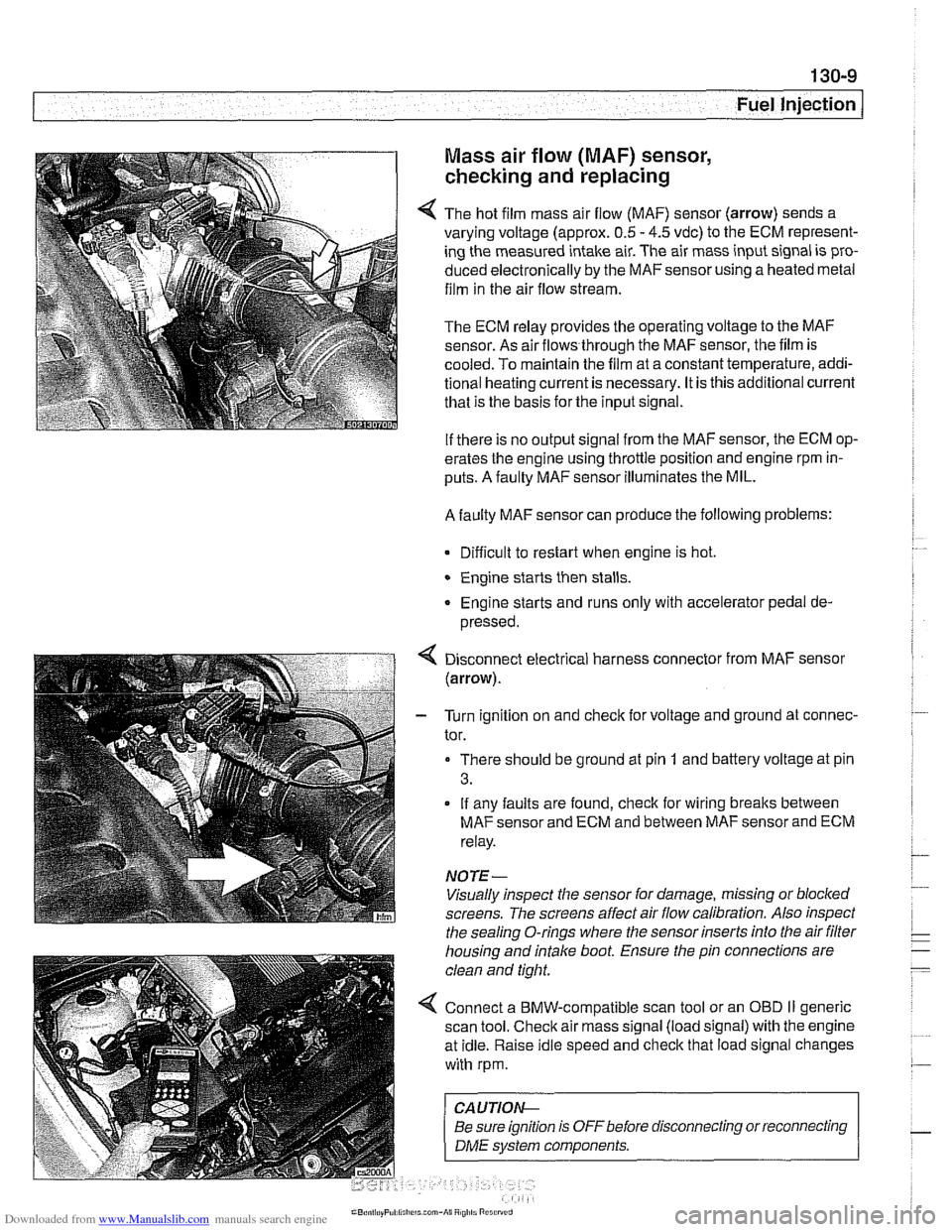
4 The hot film mass air flow (MAF) sensor (arrow) sends a
varying voltage (approx.
0.5 - 4.5 vdc) to the ECM represent-
ing the measured intake air. The air mass input signal is pro-
duced electronically by the
MAFsensorusing a heated metal
film in the air flow stream.
The ECM relay provides the operating voltage to the MAF
sensor. As air flows through the MAF sensor, the film is
-
cooled. To maintain the film at a constant temperature, addi-
tional heating current is necessary. It is this additional current
that is the basis for the input signal.
If there is no output signal from the MAF sensor, the ECM op-
erates the engine using throttle position and engine rpm in-
puts. A faulty MAF sensor illuminates the MIL.
A faulty MAF sensor can produce the following problems:
Difficult to restart when engine is hot.
Engine starts then stalls.
Engine starts and runs only with accelerator pedal de-
pressed.
Disconnect electrical harness connector from MAF sensor
(arrow).
- Turn ignition on and check for voltage and ground at connec-
tor.
There should be ground at pin
1 and battery voltage at pin
3.
If any faults are found, check for wiring breaks between
MAF sensor and ECM and between MAF sensor and ECM
relay.
NOTE-
Visually inspect the sensor for damage, missing or blocked
screens. The screens affect air flow calibration. Also inspect
the sealing O-rings where the sensor inserts into the air
filter
housing and intake boot. Ensure the pin connections are
clean and tight.
4 Connect a BMW-compatible scan tool or an OBD II generic
scan tool. Check air mass signal (load signal) with the engine
at idle. Raise idle speed and check that load signal changes
with rpm.
CA UTIOI\C
Be sure ignition is OFFbefore disconnecting or reconnecting r
1 DME svstem components. 1
Page 419 of 1002
Downloaded from www.Manualslib.com manuals search engine
Fuel Injection
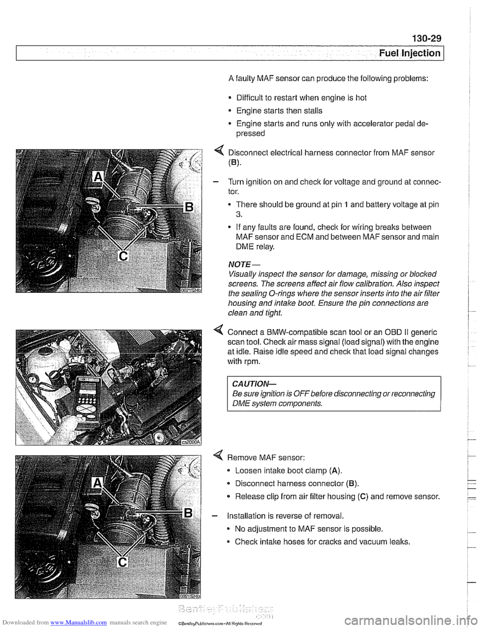
A faulty MAF sensor can produce the following problems:
Difficult to restart when engine is hot
Engine starts then stalls
* Engine starts and runs only with accelerator pedal de-
pressed
4 Disconnect electrical harness connector from MAF sensor
(B).
- Turn ignition on and checlc for voltage and ground at connec-
tor.
There should be ground at pin
1 and battery voltage at pin
3.
- If any faults are found, checlc for wiring breaks between
MAF sensor and ECM and between MAF sensor and main
DME relay.
NOTE-
Visually inspect the sensor for damage, missing or blocked
screens. The screens affect air flow calibration. Also inspect
the sealina
0-rinas where the sensor inserts into the air filter - - housing and intake boot. Ensure the pin connections are
clean and tight.
4 Connect a BMW-compatible scan tool or an OED II generic
scan tool.
Checlc air mass signal (load signal) with the engine
at idle. Raise idle speed and
checlc that load signal changes
with rpm.
CAUTION-
Be sure ignition is OFFbefore disconnecting or reconnecting
DME system components.
Remove MAF sensor:
Loosen intake boot clamp
(A).
Disconnect harness connector (6).
* Release clip from air filter housing (C) and remove sensor.
- Installation is reverse of removal.
No adjustment to MAF sensor is possible.
Check intake hoses for cracks and vacuum
lealts.
Page 422 of 1002
Downloaded from www.Manualslib.com manuals search engine
Fuel Injection
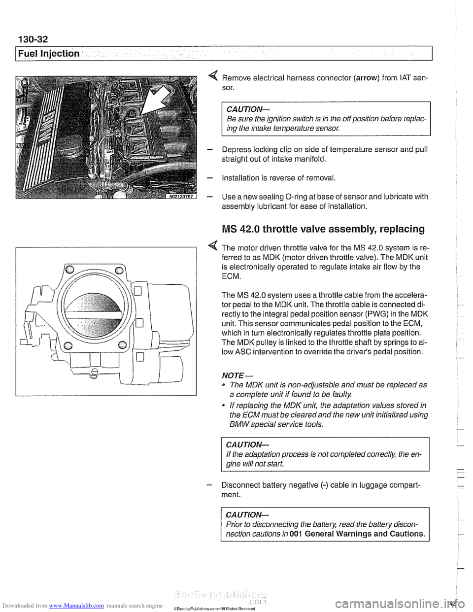
4 Remove electrical harness connector (arrow) from IAT sen-
sor.
CAUTION-
Be sure the ignition switch is in the off position before repiac-
ins the intake temperature sensor.
- Depress loclting clip on side of temperature sensor and pull
straight out of intake manifold.
- Installation is reverse of removal
- Use a new sealing O-ring at base of sensor and lubricate with
assembly lubricant for
ease of installation
MS 42.0 throttle valve assembly, replacing
< The motor driven throttle valve for the MS 42.0 system is re-
- ferred to as MDK (motor driven throttle valve). The MDK unit
is electronically operated to regulate intake air flow by the
ECM.
The
MS 42.0 system uses a throttle cable from the accelera-
tor pedal to the MDK unit. The throttle cable is connected di-
rectly to the integral pedal position sensor
(PWG) in the MDK
unit. This sensor communicates pedal position to the ECM,
which in turn electronically regulates throttle plate position.
The MDK pulley is linked to the throttle shaft by springs to al-
low ASC intervention to override the driver's pedal position.
NO TE -
The MDIC unit is non-adjustable and must be replaced as
a complete unit if found to be faulty.
if replacing the
MDK unit, the adaptation values stored in
the ECM must be clearedand the new unit initialized using
BMW special service tools.
CAUTION-
If the adaptation process is not completed correct& the en-
gine wiii
not start.
- Disconnect battery negative (-) cable in luggage compart-
ment.
CAUTION-
Prior to disconnecting the battern read the battely discon-
nection cautions in
001 General Warnings and Cautions.
Page 425 of 1002
Downloaded from www.Manualslib.com manuals search engine
Fuel Injection
MS 43.0 throttle valve assembly, replacing
The electronic throttle valve assembly forthe MS43.0 system
is referred to as
EDK (electronic throttle valve). There is no
mechanical (cable) link between the accelerator pedal and
the throttle plate.
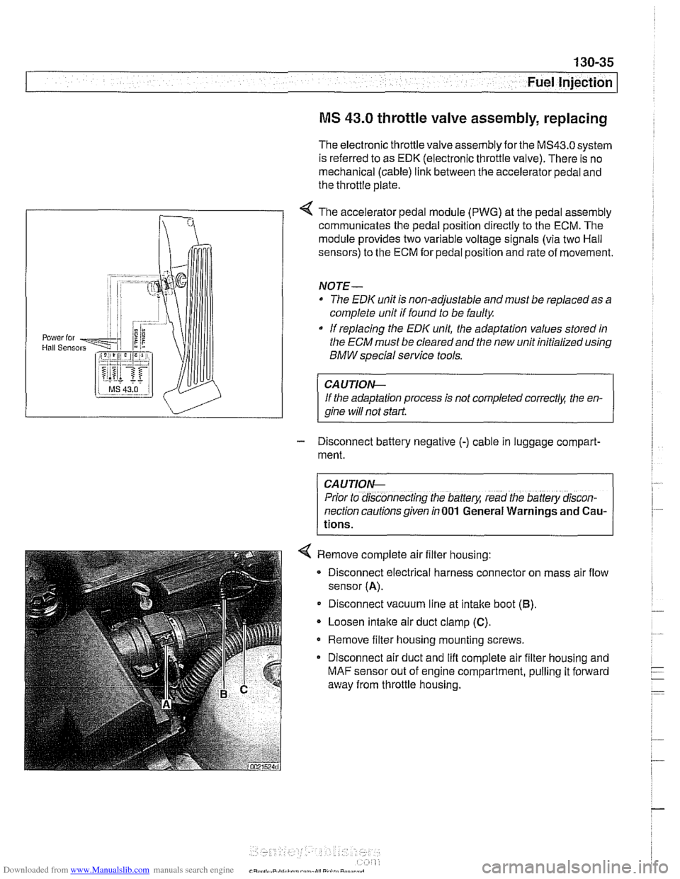
< The accelerator pedal module (PWG) at the pedal assembly
communicates the pedal position directly to the ECM. The
module provides two variable voltage signals (via two Hail
sensors) to the ECM for pedal position and rate of movement.
NOTE-
The EDK unit is non-adjustable and must be replaced as a
complete unit if found to be faulty
If replacing the
EDK unit, the adaptation values stored in
the
ECM must be cleared and the new unit initialized using
BMW special service tools.
CAUTIOIG
If the adaptation process is not completed correctk the en-
qine will not start
- Disconnect battery negative (-) cable in luggage compart-
ment.
CAUTION-
Prior to disconnecting the battery, read the battery discon-
nection cautions given in
001 General Warnings and Cau-
tions.
< Remove complete air filter housing:
- Disconnect electrical harness connector on mass air flow
sensor
(A).
Disconnect vacuum line at intake boot (6).
Loosen intaite air duct clamp (C).
Remove filter housing mounting screws.
Disconnect air duct and lift complete air filter housing and
MAF sensor out of engine compartment, pulling it forward
away from throttle housing.
Page 428 of 1002
Downloaded from www.Manualslib.com manuals search engine
130-38
Fuel Injection
Throttle cable, adjusting
(MS 42.0)
The throttle assembly on MS 42.0 cars uses a throttle cable.
The cable should be adjusted any time it is disconnected or
replaced. This procedure requires the factory scan tool or an
equivalent to read and adjust throttle angle. It is recommend-
ed the procedure be done by an authorized
BMW dealer ser-
vice department
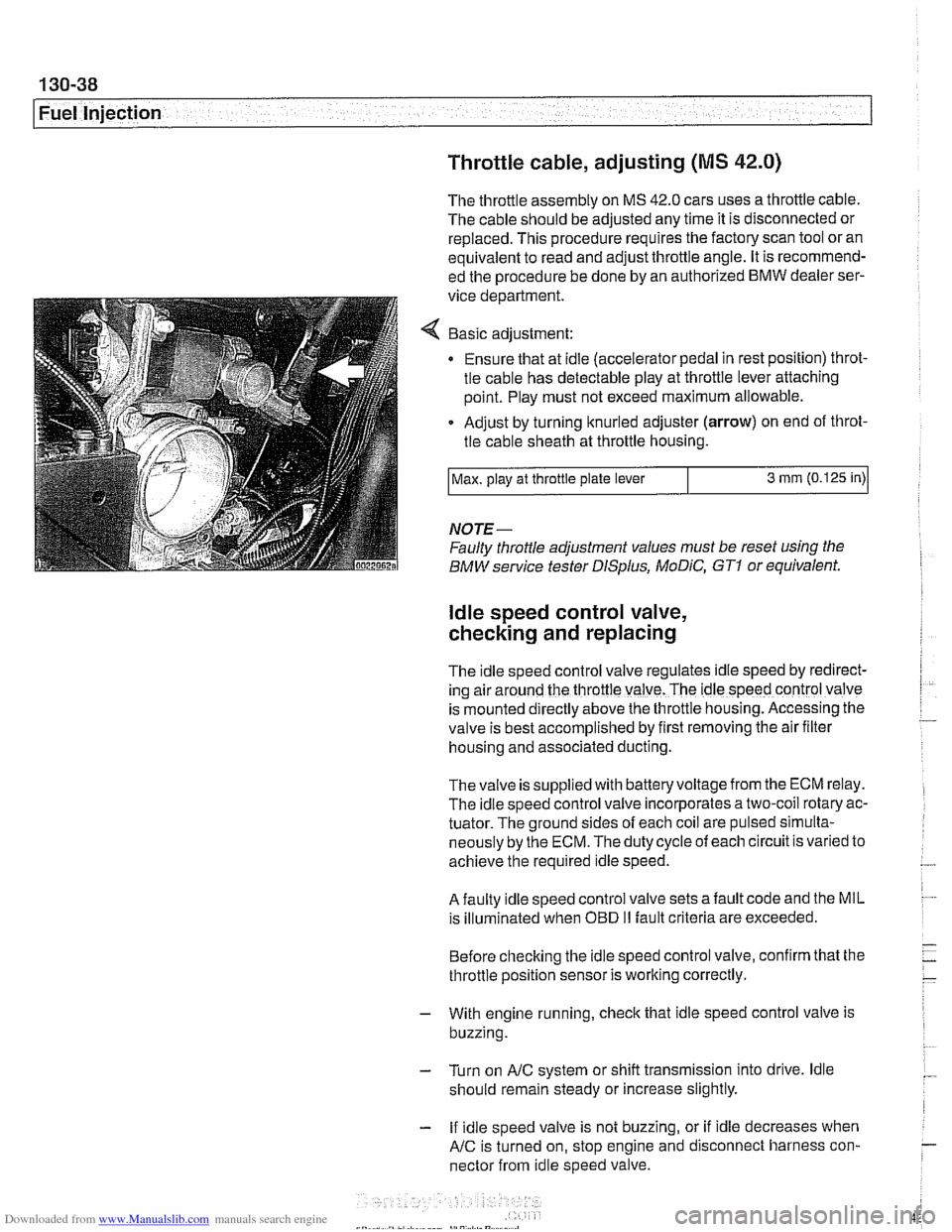
Basic adjustment:
Ensure that at idle (accelerator pedal in rest position) throt-
tle cable has detectable play at throttle lever attaching
point. Play must not exceed maximum allowable.
Adjust by turning knurled adjuster
(arrow) on end of throt-
tle cable sheath at throttle housing.
NOTE-
Faulty throttle adjustment values must be reset using the
BMW service tester
DISplus, MoDiC, GTI or equivalent.
Max.
play at throttle plate lever
ldle speed control valve,
checking and replacing
3 mm (0.125 in)
The Idle speed control valve regulates Idle speed by red~rect-
ing air around the throttle valve. The ldle speed control valve
is mounted
d~rectly above the throttle housing. Accessing the
valve is best accomplished by
flrst removing the air fllter
housing and associated ducting.
Thevalve is supplied with batteryvoltage from the ECM relay.
The idle speed control valve incorporates a two-coil rotary ac-
tuator. The ground sides of each coil are pulsed simulta-
neously by the ECM. The duty cycle of each circuit is varied to
achieve the required idle speed.
A faulty idle speed control valve sets a fault code and the MIL
is illuminated when
OED II fault criteria are exceeded.
Before checking the idle speed control valve, confirm that the
throttle position sensor is working correctly.
- With engine running, check that idle speed control valve is
buzzing.
- Turn on AIC system or shift transmission into drive. ldle
should remain steady or increase slightly.
- If idle speed valve is not buzzing, or if idle decreases when
AIC is turned on, stop engine and disconnect harness con-
nector from idle speed valve.
Page 448 of 1002
Downloaded from www.Manualslib.com manuals search engine
Fuel Injection Evaporative fuel system pressure leak
diagnosis, overview
(M5.2.1 only)
1998 540i models are equipped with an evaporative fuel sys-
tem pressure leak diagnosis system. The main component of
this system is the leak diagnosis pump (LDP). The function of
the LDP is to pressurize the fuel tank and the evaporative
emission system for the purpose of detecting
leaks. This sys-
tem is capable of detecting a leak as small as 0.5 mm.
The LDP, located in the left rear wheel housing, is a unitized
component that contains the following:
Vacuum chamber. Pneumatic pump chamber.
DME activated vacuum solenoid
Reed switch (provides switched voltage
feedback signal to
ECM).
The vacuum supply line is in the wiring harness from the en-
gine compartment and runs down the driver's side of the vehi-
cle.
The canister vent valve is integrated into the LDP, which is
electrically controlled by the ECM. The canister vent valve is
opened to provide fresh air entry into the fuel system only dur-
ing purge operation.
- Purge operation characteristics:
Off idle through full throttle: purge valve opened by pulse
width modulated (PWM) control of the ECM. PWM duty cy-
cle varies by engine operating conditions
(e.g. warm idle,
purge valve opened slightly; cold
idleldecel with engine
temp
< 67" C, purge valve always closed).
Page 458 of 1002
Downloaded from www.Manualslib.com manuals search engine
130-68
Fuel Injection
0
4 The ME 7.2 uses a non-return fuel rail. The fuel pressure reg-
ulator is integrated into the fuel filter.
I iY.,lii,in
4 The M62 TU engine uses a continuously variable VANOS
system at each intake camshaft. This system enhances en-
gine performance and reduces tailpipe emissions. Both cam-
shafts are adjusted simultaneously within
20" (maximum) of
the camshafts rotational axis. This equates to a maximum
span of
40°crankshaft rotation.
regulalor from luel pump
NOTE-
The fuel filter is available as a replacement part without the
fuel pressure regulator. When replacing the fuel filter, trans-
fer the fuel pressure regulator from the old
filter to the new fil-
ter.
Engine idle speed control is a function of the EDK. The M62
TU engine does not use a separate idle control valve.
Mmn CON,ROL
EML
< The M62 TU engine uses an electrically controlled throttle
valve called EDK. The throttle plate is positioned by a DC
gear reduction motor based on inputs signals to the ECM
from the pedal position sensor (PWG).
When the accelerator pedal is moved, the PWG provides a
change in the monitored signals. The ME
7.2 control module
compares the input signal to a programmed map and appro-
priately activates the EDK motor via proportional pulse width
modulated control signals. The control module self-checks its
activation of the EDK motor via the EDK feedbaclc
potentiom-
eters.