engine cel BMW 530i 2001 E39 Workshop Manual
[x] Cancel search | Manufacturer: BMW, Model Year: 2001, Model line: 530i, Model: BMW 530i 2001 E39Pages: 1002
Page 4 of 1002
Downloaded from www.Manualslib.com manuals search engine
Selected Boolcs and Repair Information from Bentley Publishers
MINI Cooper
MINI Cooper Service Manual: 2002-2004 Bc,illc!! Pirl~lisl!~~ ISBN 0-8376-1068-0 AlexZanardi - My Swectest Victory rllex Zmmrdi itjill! Ginrz11,cn Gns~x~ri,,i ISBN (1-8376-1249-7
BMW 3 Series IE36) Scrvire Manual: 1992-1998,318ilisliC. 323is/iC, 3?5i/is/iC, 328ilisliC, M3 Be~iili.!~ Pirl?lisliers ISBN 0-8376-0326-9
BMW
5 Series Scrvicc Manual: 1997-2002 525i, 528i. 530i. 540i, Sedan, Sport Wagon Bcrrlluy P~rlilishens ISBN 0-8376-0317-X
Porsclze Tl~c Unfair Advantage hlirrk Do,~ult,re ISBN 0-8376-0073-Iilrcj; Porsche: Excellcncc Was Expected I
Porschc 911 Enthusiast's CompanionT3' Aiirinri Slr~,tzlli~~r ISBN 0-8376-0293-9
BMW 6 Scries Enthusiasl's CompanionTh1 Jc~.li'iil!/ liV0l10li ISBN 0-8376-0193-2 Driving Tlw Skip Bizl.bul- Riicing Sclaiol ISBN 0-8376-0227-0
BMW 7 Series Servicc Manual:1988-1994, 735i,735iL, 74%. 740iL. 750iL Beritlc!/ I'irblislrens ISBN 0-8376-0328-5
A French I
Bosch 1-landbook for Automotive Elcctrics and Elcchonics Rillrcr I Bwcli, GrjilrH ISBN 0-8376-1050-8
Bosch Handbook for Diesel-Engine Managcmcnt Ril1iei.t Bosdl, ClrrbH ISBN 0-8376-1051-6
Bosch Handbook for
Gasolinc-Engine Management Robcrf Bosclr, G~ribH ISBN 0-8376-1052-4
'7
Battle for lhe Bcelle I
Jells, Golf, GTI Scrvicc Manual: 1999-2005 1.8L lurbo, 1.9LTDI diesel, PD dicscl, 2.0L ga5aline. 2.81 VRG B~.!iIlcy Pt,blislicrs ISBN 0-8376-125-9
New Bcctle ServiceManual:1998-20021.8L turbo, 1.91 TDI diesel, 2.0L gasoline Bailicy P~irirlishers ISBN 0-8376-0376-5
New Bcctle 1998-2005, New Beetle Convcrtible2003-2005 Official Factory
Rcpair Manual an CD-ROM
I~olkiatgurr ~JAriicricn ISBN 9784-8376-1265-2
Boscll Fuel Injection and Enginc Management Clml-Its 0. Pmbsi, SAE ISBN 0-8376-0300-5 Clzevrolet
Corvctlc Illustralcd Encyclopedia Torn Beifurli ISBN 0-8376-0928-3
Racc Car Aerodynamics losupli Kntz ISBN 0-8376-014>8
Road &Track Illustrated Automotive
Dictionary
Joltri Dilrkl ISBN 0-8376-11143-6
Scientific Design of Exl~aust and Intake Systems I'lrililr H. S,sillr 0-8376-0309-9 Corvette Fuel
Injection &Electronic Enginc Managcment 1982-2001: Clmrlcs 0. I1rol,sl, SAE ISBN 0-8376-0861-9
I'acrat Ser\,irc hl.>nu.~l: 1998-2004.1.81. lurbu, 2.RL Vb, .l.IIL \\'8, inrludinl: tv.~gc>n and 4blOTION Giiitlc!/ P~iiblislicrs ISBN 0-8376-0360-2 Zora Arkus-Duntov:Thc Lcgcnd Behind corvt.ttc Je1.q Birl-1011 ISBN 0-8376-0858-9
Ci~evmlcl by the Numbers 1965-1969: The
Essential Chcvrolct Paris Refcrcncc illn,i Cnl2i11 ISBN 0-8376-0956-9
Passat. Passat Waron 1998-2005 Official
Gnlf,
GTI, Jctta 1993-1999, Cabrio 199% 2002 Official Factory Repair Manual on
CD-ROM
Volhsiraigu>t oJA,rtrricn ISBN 978-0-8376-1263-8
Jetta, Golf, GTI: 1993-1999,
Cabtio: 1995- 2002 Scrvicc Manual ll~iillcy I'trblisln.~~~ ISBN 0-8376-0366-8
Alfa Romco All-Alloy Twin Cam
Companion 195G1994 1'nl Bncdulr ISBN 0-8376.0275-0
Alfa Romco Owner's Bibl~'~' 1'1~1 Bmrlul! ISBN 0-8376-0707-8
Ford
Ford Fuel Injection and Electronic Engine
Control: 1988-1993
Clinrlcs 0. Pmirsl, SrlE ISBN 0-8376-03Lll-3 Arldi
Audi A4 Repair Manual: 1996-2001.1.8L lurbo, 2.8L. including Avant and quatlro Buirile!/ Ptrhlislters ISBN 0-8376-0371-.I
EuroVan Official Factory Rcp.,ir Manual:
1992-1999
I/~llhio~sar, ifAii!wicn ISBN 0-8376-0335-8
Tbc Official Ford Mustang 5.0 Technical
Reference & I'crformancc Handbook:
1979-1993
A1 l
1998-2004, Avant 1999- 2004, allroad quallro 2001-2005, 56 Avant 2002-2004, RS6 2003-2004 Official
Factory Rcpair Manual on CD-ROM
Ai!dioJ/in,er.ini ISBN 978-0-8376-1257-7
Jccp CJ Rubuildcr's Manual: 1972-1986 MOSI~S Lltii~l ISBN 0-8376-0151-7
Jccp Owner's Biblen', Third Edition Moscs Lzrdel ISBN 0-8376-1117-2 Automotive Reference
Bcnlluy Publishers has published iewicc manualsand autornohilcboolissinrc 1950. Plcasc write to us at 1734 Mniincliusctts Ave..Cnmbridge, kIA02138,i~isit ourivcb sitc, ol-c,lll 1-800-12345'15 ini a free copy ofnurcolaiog.
BMW
BMW 23 Sarvicc Manual: 1996-2002. including 23 Roadster, 23 Coupe, M
Roadster, M Coupe
Be~illq Pi,blislicis ISBN 0-8376-1250-0
BMW 3 Scrics (Ed61 Scrvicc Manual:
Mcrcedes-Bcnz Technical C~mpanion'~~' Bu,rllu!! P,rlilislio.i ISBN 11-8376-1033-8
Mcrccdcs-Bcnz E-Class (W124) O~vner's BibleT>' : 1986-1995 llu~tilc!~ Pi~lriisiieis ISBN 11-8376-0230-(1
Urlilii-!~ P~~Blisi~~rs ISBN 11-8376-11772
Page 7 of 1002
Downloaded from www.Manualslib.com manuals search engine
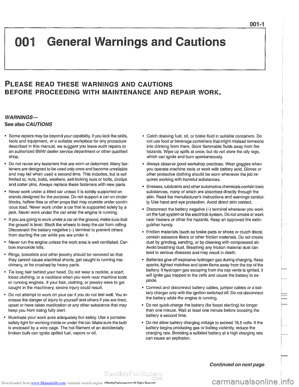
001 General Warnings and Cautions
PLEASE READ THESE WARNINGS AND CAUTIONS
BEFORE PROCEEDING
WITH MAINTENANCE AND REPAIR WORK.
WARNINGS-
See also CAUTIONS
- Some repairs may be beyond your capability. If you lack the skills, - Catch draining fuel, oil, or brake fluid in suitable containers. Do
tools and equipment, or a suitable workplace for any procedure
not use
foodor beverage containers that might mislead someone
described in this manual, we suggest you leave such repairs to
into
drinking from them. Store flammable fluids away from fire
an authorized BMW dealer service department or other qualified
hazards. Wipe up spills at once, but do not store the oily rags,
shop. which can ignite and burn spontaneously.
. Do not reuse any fasteners that are worn or deformed. Many fas- Always observe good worRshop practices. Wear qoqqles when
teners are designed to be used only once and become
unreliable you operate machine tools or work with battery acid:kloves or
and mav fail when used a second time. This includes, but is not other
~rotective clothino should be worn whenever the iob re-
limited io, nuts, bolts, washers, self-locking nuts or bolts, clrclips yires' working with harmful substances.
and cotter pins. Always replace these fasteners with new parts.
Greases, lubricants and other automotive chemicals contain toxic
. Never work under a lifted car unless it is solidly supported on
substances, many of which are absorbed directly through the
stands
desiqned for the purpose. Do not supeort a car on cinder
skin. Read the manufacturer's instructions and warninos careful-
blochs, hollow tiles orotherbrops that may drurnbie undercontin-
uous toad. Never work under a car that is supported solely by a
iack. Never work under the car
while the enqine is runninq. - -
If you aregoing to work underacaron the ground, makesure that
the ground is level. Block the wheels to
keep the car from rolling.
Disconnect the battery negative
(-) terminal to prevent others
from starting the car while you are under it.
- Never run the engine unless the work area is well ventilated. Car-
bon monoxide kills.
Rings, bracelets and other jewelry should be removed so that
they cannot cause electrical shorts, get caught in running ma-
chinery, or be crushed by heavy parts.
- Tie long hair behind your head. Do not wear a necktie, a scarf.
loose clothing, or a necklace when you work near machine tools
or running engines. if your hair, clothing, or jewelry were to get
caught in the machinery, severe injury could result.
DO not attempt to
work on your car if you do not feel well. You in-
crease the
danger of injuryto yourseliand others if you are tired,
uDset or have taken medication or anv other substance that mav
keep you from being fully alert.
Illuminate your work area adequately but safely. Use a portable
iy. Use hand and eye protection. Avoid direct skin conGct.
Disconnect the battery negative (-) terminal whenever you work
on the fuel system
orthe electrical system. Do not smokeorwork
near heaters or other fire hazards. Keep an approved fire extin-
guisher handy.
. Friction materials (such as brake pads or shoes or clutch discs)
contain asbestos fibers or other friction materials. Do not create
dust by grinding, sanding, or by cleaning with compressed air.
Avoid breathing dust. Breathing any
friclion material dust can
lead to serious diseases and may result in death.
Batteries
giveoff explosive hydrogen gas during charging. Keep
sparks, lighted matches and open flame away from the top of the
battery. If hydrogen gas escaping from the cap vents is ignited, it
will ignite gas trapped in the cells and cause the battery to ex-
plode.
Connect and disconnect battery cables, jumper cables or a bat-
tery charger only wilh the ignition switched off. Do not disconnect
the battery while the engine is running.
Do not quick-charge the battery (for boost starting) for longer
than one minute. Wait at least one minute before boosting the
battery a second time.
. . safety lighiforworking lnsideor under the car. Make sure the bulb - Do not allow battery charging vollage to exceed 16.5 volts. If the
is enclosed bv a wire caoe. The hot filament of an accidentallv
batten! beoins ~roducina oas or boilino violentiv, reduce the
broken bulb can ignite spilled
fuel, vapors or oil. , - - - charglng rate. ~oostlng a sutfaled battery at a igh charging rate
can cause an
explosion.
-
Continued on next page
Page 14 of 1002
Downloaded from www.Manualslib.com manuals search engine
.
General
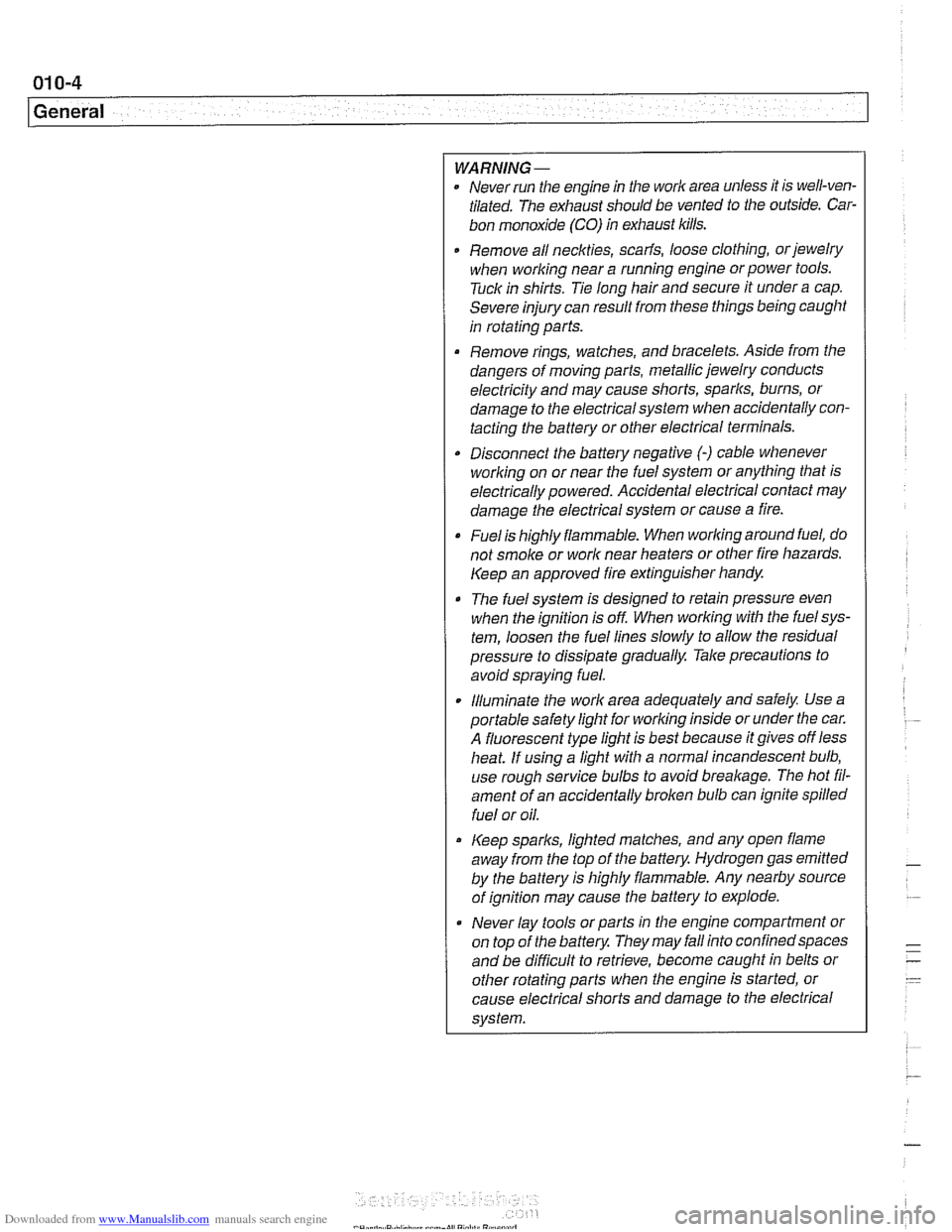
WARNING-
Never run the engine in tile work area unless it is well-ven-
tilated. The exhaust should be vented to the outside. Car-
bon monoxide (CO) in exhaust kills.
Remove all neckties,
scarfs, loose clothing, or jewelry
when working near a running engine or power tools.
Tuck in shirts. Tie long hair and secure it under a cap.
Severe injury can result from these things being
caugiit
in rotating parts.
Remove rings, watches, and bracelets. Aside from the
dangers of moving parts, metallic jewelry conducts
electricity and may cause shorts, sparks, burns, or
damage to the electricalsystem when accidentally con-
tacting the battery or other electrical terminals.
Disconnect the battery negative
(-) cable whenever
working on or near the fuel system or anything that is
electrically powered. Accidental electrical contact may
damage the electrical system or cause a fire.
Fuelis highly flammable. When working around fuel, do
not
smoke or work near heaters or other fire hazards.
Keep an approved fire extinguisher handy.
The fuel system is designed to retain pressure even
when the ignition is off When worlcing with the
fuelsys-
tem, loosen the fuel lines slowly to allow the residual
pressure to dissipate gradually. Take precautions to
avoid spraying fuel.
. Illuminate the worlc area adequately and safely Use a
portable safety light for worlcing inside or under the car.
A fluorescent type
light is best because it gives off less
heat. If using a light with a normal incandescent bulb,
use rough service bulbs to avoid
breakage. The hot fil-
ament of an accidentally broken bulb can ignite spilled
fuel or oil.
Keep sparks, lighted matches, and any open flame
away from the top of the battery. Hydrogen gas
emitted
by the battery is highly flammable. Any nearby source
of ignition may cause the battery to explode.
Never lay
tools or parts in the engine compartment or
on top of the battery. They may
fallinto confinedspaces
and be difficult to retrieve, become caught in belts or
other rotating parts when the engine is started, or
cause electrical shorts and damage to the electrical
system.
Page 33 of 1002
Downloaded from www.Manualslib.com manuals search engine
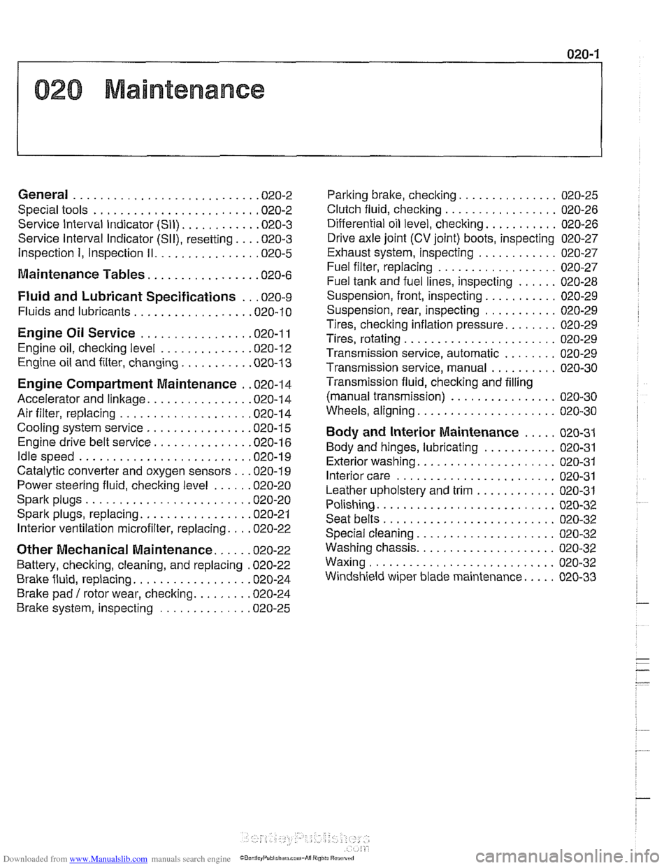
020 Maintenance
General ........................... .02 0.2
Special tools ........................ .02 0.2
Service Interval Indicator (Sll) ........... .02 0.3
Service Interval Indicator (Sll), resetting ... .02 0.3
Inspection I, Inspection 11 ............... .02 0.5
Maintenance Tables ................ .02 0.6
Fluid and Lubricant Specifications .. .02 0.9
Fluids and lubricants ................. .02 0.10
Engine Oil Service ................ .02 0.1 I
Engine oil. checking level ............. .02 0.12
Engine oil and filter. changing .......... .02 0-13
Engine Compartment Maintenance . .02 0.14
Accelerator and linkage ............... .02 0.14
Air filter. replacing ................... .02 0.1 4
Cooling system service ............... .02 0.15
Engine drive belt service .............. .02 0.16
Idlespeed .......................... 020-19
Catalytic converter and oxygen sensors .. .02 0.19
Power steering fluid, checking level ..... .02 0.20
Spark plugs ........................ .02 0.20
Spark plugs, replacing ................ .02 0.21
Interior ventilation microfilter, replacing ... .02 0.22
Other Mechanical Maintenance ..... .02 0.22
Battery, checking. cleaning. and replacing .02 0-22
Brake fluid. replacing ................. .02 0-24
Brake pad 1 rotor wear. checking ........ .02 0.24
Brake system, inspecting ............. .02 0.25
Parking brake. checking ............... 020-25
Clutch fluid. checking ................. 020-26
Differential oil level. checking ........... 020-26
Drive axle joint (CV joint) boots. inspecting 020-27
Exhaust system. inspecting ............ 020-27
Fuel filter. replacing .................. 020-27
Fuel tank and fuel lines. inspecting ...... 020-28
Suspension. front. inspecting ........... 020-29
Suspension. rear. inspecting ........... 020-29
Tires. checking inflation pressure ........ 020-29
Tires. rotating ....................... 020-29
Transmission service. automatic ........ 020-29
Transmission service. manual .......... 020-30
Transmission fluid. checking and filling
(manual transmission)
................ 020-30
Wheels. aligning ..................... 020-30
Body and Interior Maintenance ..... 020-31
Body and hinges. lubricating ........... 020-31
Exterior washing ..................... 020-31
Interior care ........................ 020-31
Leather upholstery and trim ............ 020-31
Polishing ........................... 020-32
Seat belts .......................... 020-32
Special cleaning ..................... 020-32
Washing chassis ..................... 020-32
Waxing ............................ 020-32
Windshield wiper blade maintenance ..... 020-33
Page 46 of 1002
Downloaded from www.Manualslib.com manuals search engine
020-1 4
Maintenance
- When oil flow has diminished to an occasional drip, reinstall
drain plug with a new metal sealing washer and torque plug.
Tightening torque Engine oil drain plug to oil pan
25 Nrn (1.8 ft-lb)
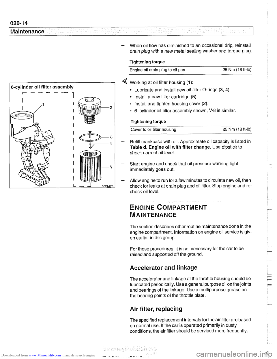
6-cylinder oil filter assembly
r------ 1
< Working at oil filter housing (1):
Lubricate and install new oil filter O-rings (3, 4).
Install a new filter cartridge (5).
lnstall and tighten housing cover (2).
6-cylinder oil filter assembly shown, V-8 is similar.
Tightening torque Cover to oil filter housing
25 Nm (1.8 it-lb)
- Refill crankcase with oil. Approximate oil capacity is listed in
Tabled. Engine oil with filter change. Use dipstick to
check correct oil level.
- Start engine and check that oil pressure warning light
immediately goes out.
- Allow engine to run fora few minutes to circulate new oil, then
check for leaks at drain plug and oil filter. Stop engine and re-
check oil level
The section describes other routine maintenance done in the
engine compartment. Information on engine oil service is
giv-
enkar~ier inthis group.
For these procedures, it is not necessary for the car to be
raised and supported off the ground.
Accelerator and linkage
The accelerator and linkage at the throttle housing should be
lubricated periodically. Use ageneral purposeoil on the joints
and bearings of the linkage. Use a multipurpose grease on
the bearing points of the throttle plate.
Air filter, replacing
The specified replacement intervals forthe air filter are based
on normal use. If the car is operated primarily in dusty
conditions, the air filter should be serviced more frequently.
Page 69 of 1002
Downloaded from www.Manualslib.com manuals search engine
Engine identifying features
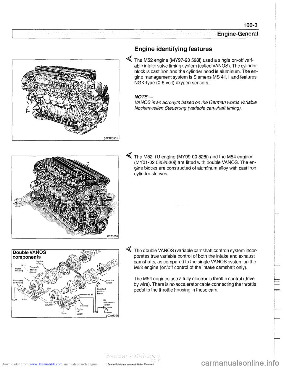
4 The M52 engine (MY97-98 528i) used a single on-off vari-
able intake valve timing system (called VANOS). The cylinder
block is cast iron and the cylinder head is aluminum. The en-
gine management system is Siemens MS 41
.I and features
NGK-type (0-5 volt) oxygen sensors.
NOTE-
VANOS is an acronym based on the German words Variable
Nocltenwellen Steuerung (variable camshaft timing).
4 The M52 TU engine (MY99-00 5281) and the M54 engines
(MY01-02 525il530i) are fitted with double VANOS. The en-
gine
blocits are constructed of aluminum alloy with cast iron
cylinder sleeves.
4 The double VANOS (variable camshaft control) system incor-
porates true variable control of both the
intake and exhaust
camshafts, as compared to the single VANOS system on the
M52 engine
(onloff control of the intaite camshaft only).
The M54 engines use a fully electronic throttle control (drive
by wire). There is no accelerator cable connecting the throttle
pedal to the throttle housing in these cars.
Page 70 of 1002
Downloaded from www.Manualslib.com manuals search engine
100-4
I Engine-General
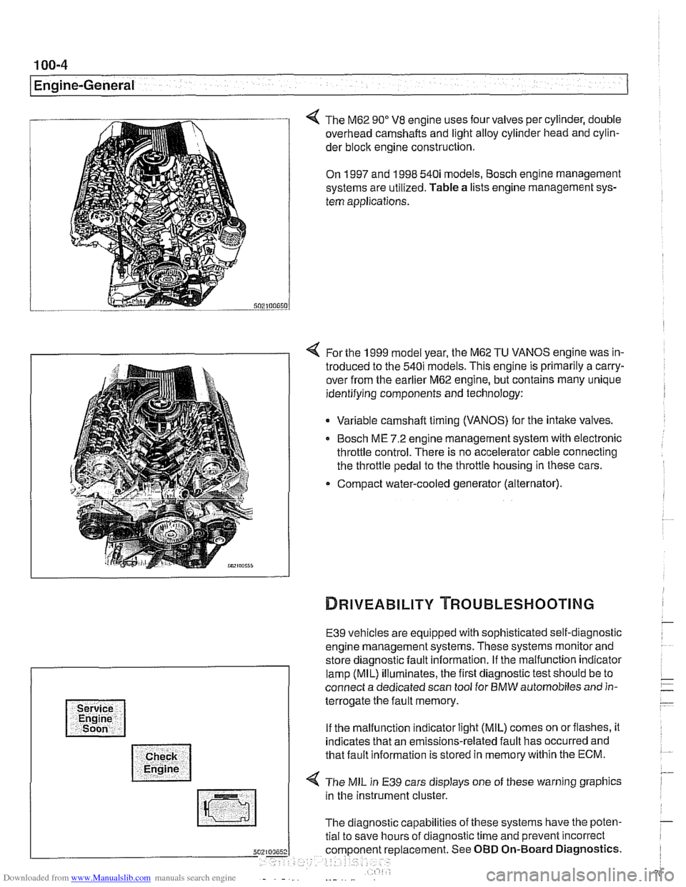
The M62 90" V8 engine uses four valves per cylinder, double
overhead camshafts and light alloy cylinder head and cylin-
der
bloclc engine construction.
On 1997 and 1998 540i models, Bosch engine management
systems are utilized. Table a lists engine management sys-
tem applications.
4 For the 1999 model year, the M62 TU VANOS engine was in-
troduced to the 540i models. This engine is primarily a carry-
over from the earlier M62 engine, but contains many unique
identifying components and technology:
Variable camshaft timing (VANOS) for the intake valves.
Bosch ME 7.2 engine management system with electronic
throttle control. There is no accelerator cable connecting
the throttle pedal to the throttle housing in these cars.
Compact water-cooled generator (alternator).
E39 vehicles are equipped with sophisticated self-diagnostic
engine management systems. These systems monitor and
store diagnostic fault information. If the malfunction indicator
lamp (MIL) illuminates, the first diagnostic test should be to
connect a dedicated scan tool for BMW automobiles and in-
terrogate the fault memory.
If the malfunction indicator light (MIL) comes on orflashes, it
indicates that an emissions-related fault has occurred and
that fault information is stored in memory within the ECM.
4 The MIL in E39 cars displays one of these warning graphics
in the instrument cluster.
The diagnostic capabilities of these systems have the poten-
tial to save hours of diagnostic time and prevent incorrect
5 placement. See OBD On-Board Diagnostics.
Page 100 of 1002
Downloaded from www.Manualslib.com manuals search engine
11 3-6
Cylinder Head Removal and Installation
- Disable ignition system by removing DME main relay. See
610 Component Locations for relay location.
WARNING-
. The ignition system produces high voltages that can be fa-
tal. Avoid contact with exposed terminals and use
exfreme
caution when working on a car with the ignition switched on
or the engine running.
Do not touch or disconnect ignition
components while
the engine is running or being cranked by the starter.
Failure to remove the DME main relay or attempting to
disa-
bie the fuel andignition systems by other methods may result
in damaoe to the enoine control module
(ECM).
- - Remove plastic cylinder head cover(s)
,,I . ,. .*,.,,&- - Remove coil grounding straps.
I CAUTION-
I nition system components. I
- Remove coils.
- Remove spark plugs from all cylinders.
NOTE-
Check the spark plugs for oil deposits that may indicate poor
cylinder sealing, then set them aside in order. Used spark
plugs should be reinstalled in the same cylinder from which
they were removed.
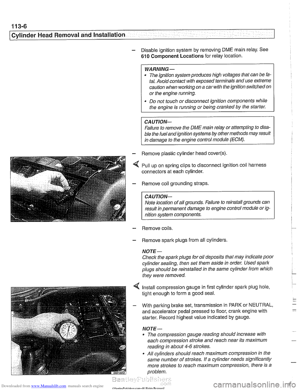
4 Install compression gauge in first cylinder spark plug hole,
tight enough to form a good seal.
- With parking brake set, transmission in PARK or NEUTRAL,
and accelerator pedal pressed to floor, crank engine with
starter. Record highest value indicated by gauge.
NOTE-
* The compression gauge reading should increase with
each compression stroke and reach near its maximum
reading in about
4-6 strokes.
All cylinders should reach maximum compression in the
same number of
strolces. If a cylinder needs significantly
more strokes to reach
maximum compression, there is a
problem.
Page 115 of 1002
Downloaded from www.Manualslib.com manuals search engine
- -.
Cylinder Head Removal and lnstallation
NOTE-
Be Sure the secondary timing chain tensioner is locked down
and the exhaust
camshaif mounting bolts are loose before
proceeding.
- Install VANOS control unit. See VANOS control unit, install-
ing
(M52 engine) in 117 Camshaft Timing Chain.
CAUTION--
Incorrect installation ofthe VANOS control may result in dam-
age to the engine valvefrain.
- Install exhaust manifolds using new gaskets and nuts. Coat
manifold studs with copper paste prior to installing nuts.
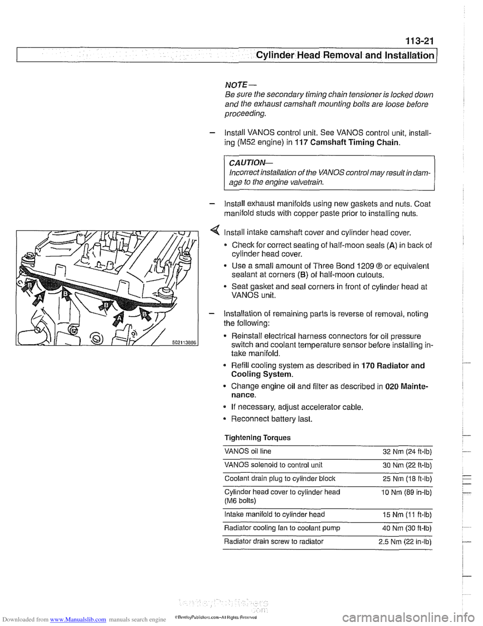
Install intake camshaft cover and cylinder
head cover.
Check for correct seating of half-moon seals
(A) in back of
cylinder head cover.
Use a small amount of Three Bond 1209
O or equivalent
sealant at corners
(6) of half-moon cutouts.
Seat gasket and seal corners in front of cylinder head at
VANOS unit.
- Installation of remaining parts is reverse of removal, noting
the following:
Reinstall electrical harness connectors for oil pressure
switch and coolant temperature sensor before installing in-
take manifold.
Refill cooling system as described in 170 Radiator and
Cooling System.
Change engine oil and filter as described in 020 Mainte-
nance.
If necessary, adjust accelerator cable.
Reconnect battery last.
Tightening Torques
VANOS oil line
32 Nm (24
ft-lb)
VANOS solenoid to control unit 30 Nm (22 ft-lb)
Coolant drain plug to cylinder
block 25 Nm (18 ft-lb)
Cylinder head cover to cylinder head
10 Nrn (89 in-lb)
(M6 bolts)
intake manifold to cylinder head 15 Nm (I 1 ft-lb)
Radiator cooling fan to coolant pump
40 Nm (30 ft-lb) - . .
Radiator drain screw to radiator 2.5 Nm (22 in-lbl
Page 150 of 1002
Downloaded from www.Manualslib.com manuals search engine
11 3-56
I Cvlinder Head Removal and Installation
- Installation of the remaining parts is reverse or removal, not-
ing the following:
- Refill cooling system as described in 170 Radiator and
Cooling System.
Change engine oil and filter as described in
020 Mainte-
nance.
If necessary, adjust accelerator cable.
a Reconnect battery.
CAUTION- To prevent damaging the engine electronic systems, installall
ground wire previously removed, including the ground wires
for the
ionition coils.
Tightening torque Coolant drain
pluq to cylinder bloclc 25 Nm (1 8 ft-lb)
Radiator cooling fan to coolant pump 40 Nm (30 ft-lb) -
Radiator drain screw to radiator 2.5
Nm (22 in-lb)
spark plug to cylinder head 25
Nm (1 8 ft-lb)
CYLINDER MEAD REMOVAL AND
INSTALLATION (M62 ENGINE)
This procedure covers cylinder head removal and installation
for the
M62 V-8 engine. Procedures forthe M62 TU VANOS
engine are not covered in this manual.
Intake manifold, left cylinder head, and right cylinder head re-
moval and installation are written as separate procedures.
The intake manifold must be removed before the cylinder
heads can be removed.
WARNING
-
Due to risk of personal injuv be sure the engine is cold be-
fore beginning the removal procedure.
Cylinder head removal and installation requires multiple spe-
cial service tools. Read the entire procedure before beginning
the repair.
Intake manifold, removal and installation,
M62 engine
- Disconnect negative (-) battery cable.
CAUTION- Prior to disconnecting the
batterj read the baitery discon-
nection cautions
in 001 General Cautions and Warnings.