Limit light BMW 535D 2014 Owners Manual
[x] Cancel search | Manufacturer: BMW, Model Year: 2014, Model line: 535D, Model: BMW 535D 2014Pages: 267, PDF Size: 5.88 MB
Page 8 of 267
Service and warranty
We recommend that you read this publication
thoroughly. Your vehicle is covered by the fol‐
lowing warranties:▷New Vehicle Limited Warranty.▷Rust Perforation Limited Warranty.▷Federal Emissions System Defect War‐
ranty.▷Federal Emissions Performance Warranty.▷California Emission Control System Lim‐
ited Warranty.
Detailed information about these warranties is
listed in the Service and Warranty Information
Booklet for US models or in the Warranty and
Service Guide Booklet for Canadian models.
Your vehicle has been specifically adapted and
designed to meet the particular operating con‐
ditions and homologation requirements in your
country and continental region in order to de‐
liver the full driving pleasure while the vehicle
is operated under those conditions. If you wish
to operate your vehicle in another country or
region, you may be required to adapt your ve‐
hicle to meet different prevailing operating
conditions and homologation requirements.
You should also be aware of any applicable
warranty limitations or exclusions for such
country or region. In such case, please contact
Customer Relations for further information.
Maintenance
Maintain the vehicle regularly to sustain the
road safety, operational reliability and the New
Vehicle Limited Warranty.
Specifications for required maintenance meas‐
ures:
▷BMW Maintenance system▷Service and Warranty Information Booklet
for US models▷Warranty and Service Guide Booklet for
Canadian models
If the vehicle is not maintained according to
these specifications, this could result in seri‐
ous damage to the vehicle. Such damage is
not covered by the BMW New Vehicle Limited
Warranty.
Data memory
Many electronic components on your vehicle
are equipped with data memories that tempo‐
rarily or permanently store technical informa‐
tion about the condition of the vehicle, events
and faults. This technical information generally
documents the state of a component, a mod‐ ule, a system or the environment:▷Operating states of system components,
fill levels for instance.▷Status messages for the vehicle and from
its individual components, e.g., wheel rota‐
tion speed/ vehicle speed, deceleration,
transverse acceleration.▷Malfunctions and faults in important sys‐
tem components, e.g., lights and brakes.▷Responses by the vehicle to special situa‐
tions, e.g., deployment of an airbag, en‐
gagement of stability control systems.▷Ambient conditions, such as temperature.
This data is purely technical in nature and is
used to detect and correct faults and to opti‐
mize vehicle functions. Motion profiles over
routes traveled cannot be created from this
data. When service offerings are used, e.g., re‐
pair services, service processes, warranty
claims, quality assurance, this technical infor‐
mation can be read out from the event and
fault memories by the service personnel, in‐
cluding the manufacturer, using special diag‐
nostic tools. You can obtain further information
there if it is needed. After a fault is corrected,
the information in the fault memory is deleted
or overwritten on a continuous basis.
When the vehicle is in use, situations are con‐
ceivable in which it might be possible to asso‐
ciate this technical data with individuals if it is
combined with other information, e.g., an acci‐
dent report, damage to the vehicle, eye wit‐
Seite 8Notes8
Online Edition for Part no. 01 40 2 928 000 - II/14
Page 44 of 267
Pinch protection systemIf the closing force exceeds a specific value as
a window closes, the closing action is inter‐
rupted.
The window reopens slightly.
Danger of pinching even with pinch pro‐
tection
Even with the pinch protection system, check
that the window's closing path is clear; other‐
wise, the closing action may not stop in certain
situations, e.g., if thin objects are present.◀
No window accessories
Do not install any accessories in the
range of movement of the windows; otherwise,
the pinch protection system will be impaired.◀
Closing without the pinch protection
system
Keep the closing path clear
Monitor the closing process and make
sure that the closing path of the window is clear; otherwise, injuries may result.◀
For example, if there is an external danger or if
ice on the windows prevents a window from
closing normally, proceed as follows:1.Pull the switch past the resistance point
and hold it there.
The pinch protection is limited and the
window reopens slightly if the closing force
exceeds a certain value.2.Pull the switch past the resistance point
again within approx. 4 seconds and hold it
there.
The window closes without pinch protec‐
tion.
Safety switch
The safety switch in the driver's door can be
used to prevent children, for example, from
opening and closing the rear windows using
the switches in the rear.
Switching on and off
Press the button.
The LED lights up if the safety func‐
tion is switched on.
Safety switch for rear operation
Press the safety switch when transport‐
ing children in the rear; otherwise, injury may
result if the windows are closed without super‐
vision.◀
Roller sunblinds
General information
If you are no longer able to move the roller sun‐
blind for the rear window after having activated
it a number of times in a row, the system is
blocked for a limited time to prevent overheat‐
ing. Let the system cool.
The roller sunblind for the rear window cannot
be moved at low interior temperatures.
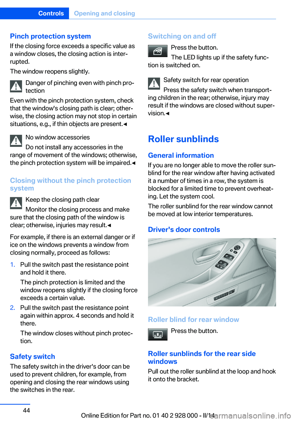
Driver's door controls
Roller blind for rear window Press the button.
Roller sunblinds for the rear side windows
Pull out the roller sunblind at the loop and hook
it onto the bracket.
Seite 44ControlsOpening and closing44
Online Edition for Part no. 01 40 2 928 000 - II/14
Page 46 of 267
Danger of pinching even with pinch pro‐
tection
Despite the pinch protection system, check
that the roof's closing path is clear; otherwise,
the closing action may not be interrupted in
certain extreme situations, such as when thin
objects are present.◀
Closing from the open position
without pinch protection
For example, if there is an external danger, pro‐
ceed as follows:1.Press the switch forward beyond the re‐
sistance point and hold.
Pinch protection is limited and the roof re‐
opens slightly if the closing force exceeds
a certain value.2.Press the switch forward again beyond the
resistance point and hold until the roof
closes without pinch protection. Make sure
that the closing area is clear.
Closing from the raised position
without pinch protection
If there is an external danger, push the switch
forward past the resistance point and hold it.
The roof closes without pinch protection.
Initializing after a power failure After a power failure during the opening or
closing process, the roof can only be operated
to a limited extent.
Initializing the system
The system can be initialized when the vehicle
is stationary and the engine is running.
During the initialization, the roof closes without
pinch protection.
Keep the closing path clear
Monitor the closing process and make
sure that the closing path of the glass sunroof
is clear; otherwise, injuries may result.◀
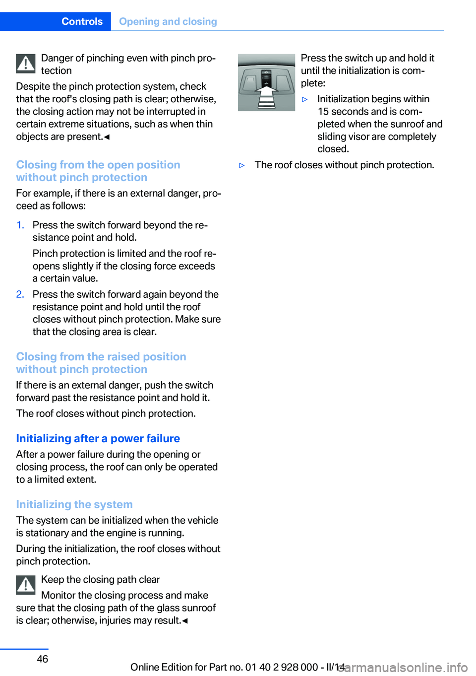
Press the switch up and hold it
until the initialization is com‐
plete:▷Initialization begins within
15 seconds and is com‐
pleted when the sunroof and
sliding visor are completely
closed.▷The roof closes without pinch protection.Seite 46ControlsOpening and closing46
Online Edition for Part no. 01 40 2 928 000 - II/14
Page 91 of 267
If speed limit detection is switched on, it can
be displayed on the info display in the instru‐
ment cluster via the onboard computer.
No Passing Information is displayed together
with the activated speed limit information.
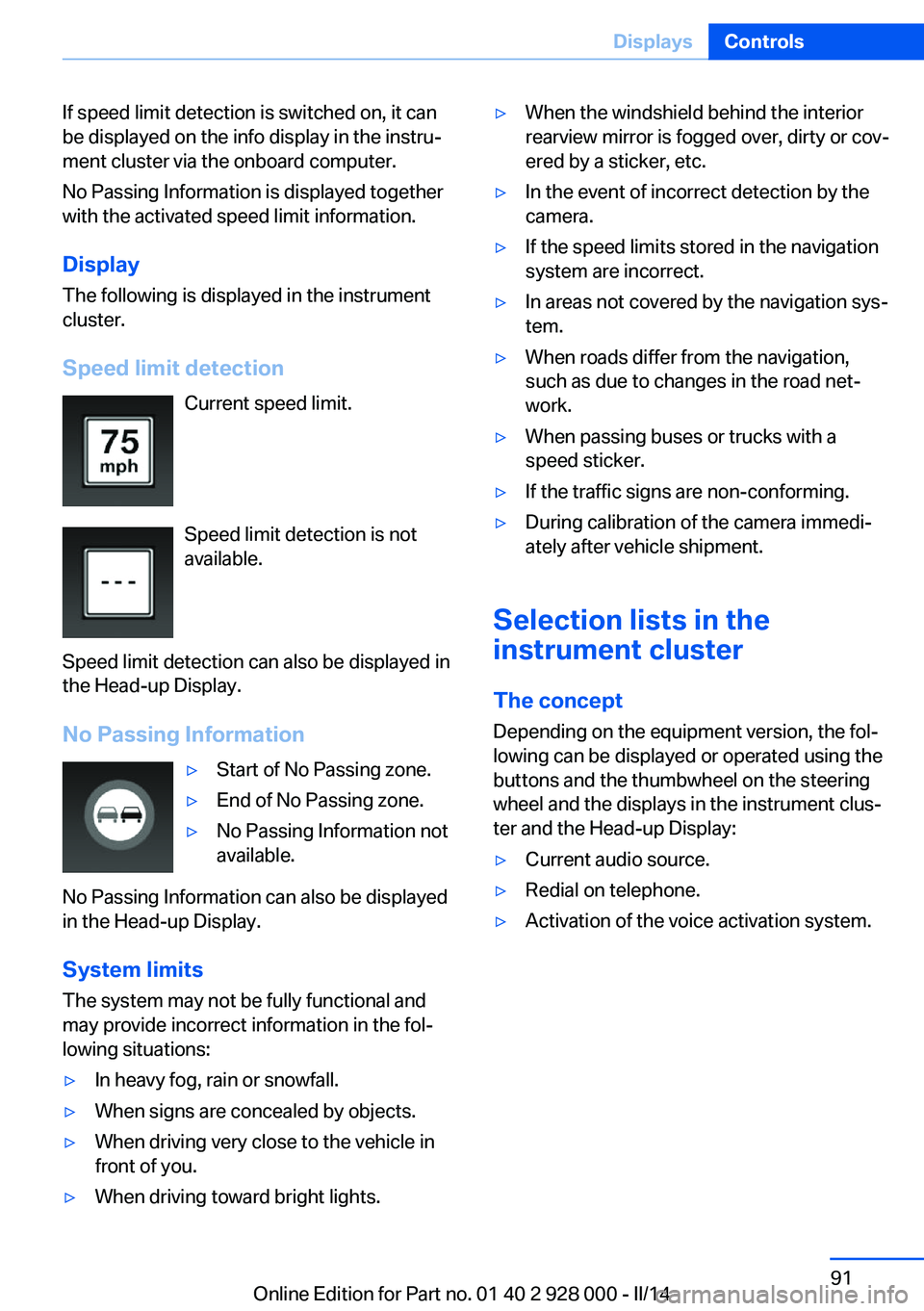
Display The following is displayed in the instrument
cluster.
Speed limit detection Current speed limit.
Speed limit detection is not
available.
Speed limit detection can also be displayed in
the Head-up Display.
No Passing Information▷Start of No Passing zone.▷End of No Passing zone.▷No Passing Information not
available.
No Passing Information can also be displayed
in the Head-up Display.
System limits
The system may not be fully functional and
may provide incorrect information in the fol‐ lowing situations:
▷In heavy fog, rain or snowfall.▷When signs are concealed by objects.▷When driving very close to the vehicle in
front of you.▷When driving toward bright lights.▷When the windshield behind the interior
rearview mirror is fogged over, dirty or cov‐
ered by a sticker, etc.▷In the event of incorrect detection by the
camera.▷If the speed limits stored in the navigation
system are incorrect.▷In areas not covered by the navigation sys‐
tem.▷When roads differ from the navigation,
such as due to changes in the road net‐
work.▷When passing buses or trucks with a
speed sticker.▷If the traffic signs are non-conforming.▷During calibration of the camera immedi‐
ately after vehicle shipment.
Selection lists in the
instrument cluster
The concept Depending on the equipment version, the fol‐
lowing can be displayed or operated using the
buttons and the thumbwheel on the steering
wheel and the displays in the instrument clus‐
ter and the Head-up Display:
▷Current audio source.▷Redial on telephone.▷Activation of the voice activation system.Seite 91DisplaysControls91
Online Edition for Part no. 01 40 2 928 000 - II/14
Page 101 of 267
▷High beams off/headlamp flasher, arrow 2.
The High-beam Assistant can be switched off
when manually adjusting the light. To reacti‐
vate the High-beam Assistant, press the but‐
ton on the turn signal lever.
System limits Personal responsibility
The high-beam assistant cannot serve as
a substitute for the driver's personal judgment
of when to use the high beams. Therefore,
manually switch off the high beams in situa‐
tions where this is required to avoid a safety
risk.◀
The system is not fully functional in situations
such as the following, and driver intervention
may be necessary:
▷In very unfavorable weather conditions,
such as fog or heavy precipitation.▷In detecting poorly-lit road users, such as
pedestrians, cyclists, horseback riders and
wagons; when driving close to train or ship
traffic; and at animal crossings.▷In tight curves, on hilltops or in depres‐
sions, in cross traffic or half-obscured on‐
coming traffic on freeways.▷In poorly-lit towns and cities and in the
presence of highly reflective signs.▷At low speeds.▷When the windshield behind the interior
rearview mirror is fogged over, dirty or cov‐
ered with stickers, etc.Camera
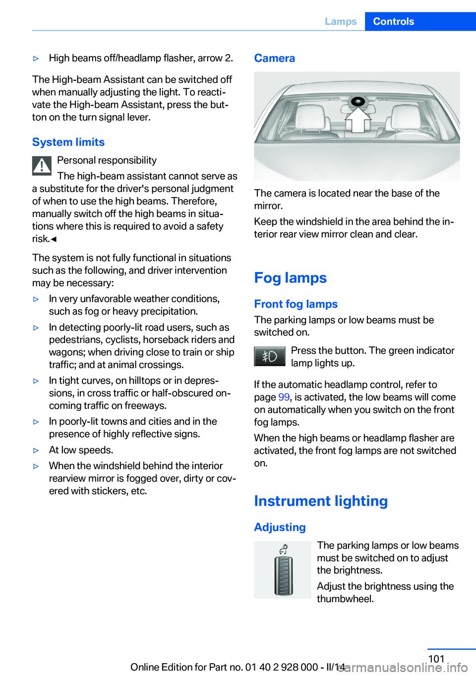
The camera is located near the base of the
mirror.
Keep the windshield in the area behind the in‐
terior rear view mirror clean and clear.
Fog lamps
Front fog lamps The parking lamps or low beams must be
switched on.
Press the button. The green indicator
lamp lights up.
If the automatic headlamp control, refer to
page 99, is activated, the low beams will come
on automatically when you switch on the front
fog lamps.
When the high beams or headlamp flasher are
activated, the front fog lamps are not switched
on.
Instrument lighting Adjusting The parking lamps or low beams
must be switched on to adjust
the brightness.
Adjust the brightness using the
thumbwheel.
Seite 101LampsControls101
Online Edition for Part no. 01 40 2 928 000 - II/14
Page 110 of 267
The system does not measure the actual infla‐
tion pressure in the tires.
Functional requirements
The system must have been initialized when
the tire inflation pressure was correct; other‐
wise, reliable signaling of a flat tire is not en‐
sured. Initialize the system after each correc‐
tion of the tire inflation pressure and after
every tire or wheel change.
Status display
The current status of the Flat Tire Monitor can
be displayed on the Control Display, e.g.,
whether or not the FTM is active.1."Vehicle Info"2."Vehicle status"3. "Flat Tire Monitor (FTM)"
The status is displayed.
Initialization
The initialization process adopts the set infla‐
tion tire pressures as reference values for the
detection of a flat tire. Initialization is started by
confirming the inflation pressures.
Do not initialize the system when driving with
snow chains.
1."Vehicle Info"2."Vehicle status"3. "Perform reset"4.Start the engine - do not drive away.5.Start the initialization with "Perform reset".6.Drive away.
The initialization is completed while driving,
which can be interrupted at any time.
The initialization automatically continues when
driving resumes.
Indication of a flat tire
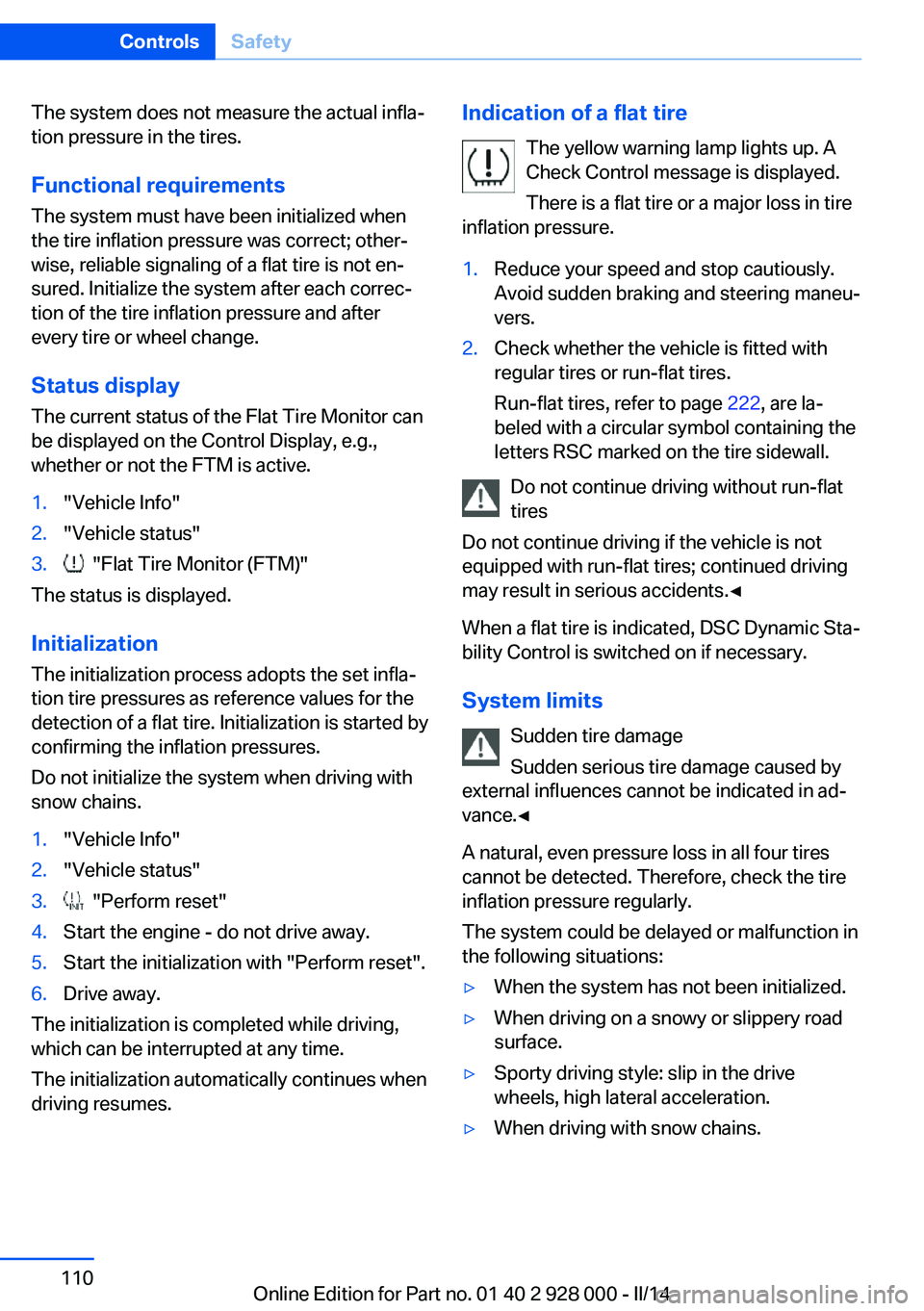
The yellow warning lamp lights up. A
Check Control message is displayed.
There is a flat tire or a major loss in tire
inflation pressure.1.Reduce your speed and stop cautiously.
Avoid sudden braking and steering maneu‐
vers.2.Check whether the vehicle is fitted with
regular tires or run-flat tires.
Run-flat tires, refer to page 222, are la‐
beled with a circular symbol containing the
letters RSC marked on the tire sidewall.
Do not continue driving without run-flat
tires
Do not continue driving if the vehicle is not
equipped with run-flat tires; continued driving
may result in serious accidents.◀
When a flat tire is indicated, DSC Dynamic Sta‐
bility Control is switched on if necessary.
System limits Sudden tire damage
Sudden serious tire damage caused by
external influences cannot be indicated in ad‐
vance.◀
A natural, even pressure loss in all four tires
cannot be detected. Therefore, check the tire
inflation pressure regularly.
The system could be delayed or malfunction in
the following situations:
▷When the system has not been initialized.▷When driving on a snowy or slippery road
surface.▷Sporty driving style: slip in the drive
wheels, high lateral acceleration.▷When driving with snow chains.Seite 110ControlsSafety110
Online Edition for Part no. 01 40 2 928 000 - II/14
Page 112 of 267
NotePersonal responsibility
The system does not serve as a substi‐
tute for the driver's personal judgment of the
traffic situation.
Be aware of the traffic situation and the vehi‐
cle's surroundings at all times, otherwise an
accident is still possible despite all warnings.◀
At a glance
Button in the vehicle
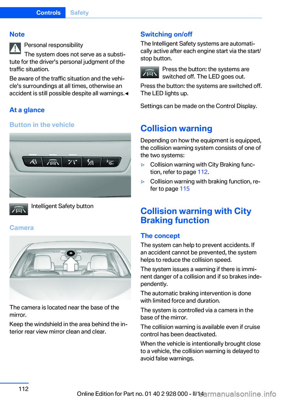
Intelligent Safety button
Camera
The camera is located near the base of the
mirror.
Keep the windshield in the area behind the in‐
terior rear view mirror clean and clear.
Switching on/off
The Intelligent Safety systems are automati‐
cally active after each engine start via the start/
stop button.
Press the button: the systems are
switched off. The LED goes out.
Press the button: the systems are switched off.
The LED lights up.
Settings can be made on the Control Display.
Collision warning
Depending on how the equipment is equipped,
the collision warning system consists of one of
the two systems:▷Collision warning with City Braking func‐
tion, refer to page 112.▷Collision warning with braking function, re‐
fer to page 115
Collision warning with City
Braking function
The concept The system can help to prevent accidents. If
an accident cannot be prevented, the system
helps to reduce the collision speed.
The system issues a warning if there is immi‐
nent danger of a collision and if so brakes inde‐
pendently.
The automatic braking intervention is done
with limited force and duration.
The system is controlled via a camera in the
base of the mirror.
The collision warning is available even if cruise
control has been deactivated.
When the vehicle is intentionally brought close
to a vehicle, the collision warning is delayed to
avoid false warnings.
Seite 112ControlsSafety112
Online Edition for Part no. 01 40 2 928 000 - II/14
Page 114 of 267
Warning with braking function
Note Adapting your speed and driving styleThe warning does not relieve the driver
of the responsibility to adapt his or her driving
speed and style to the traffic conditions.◀
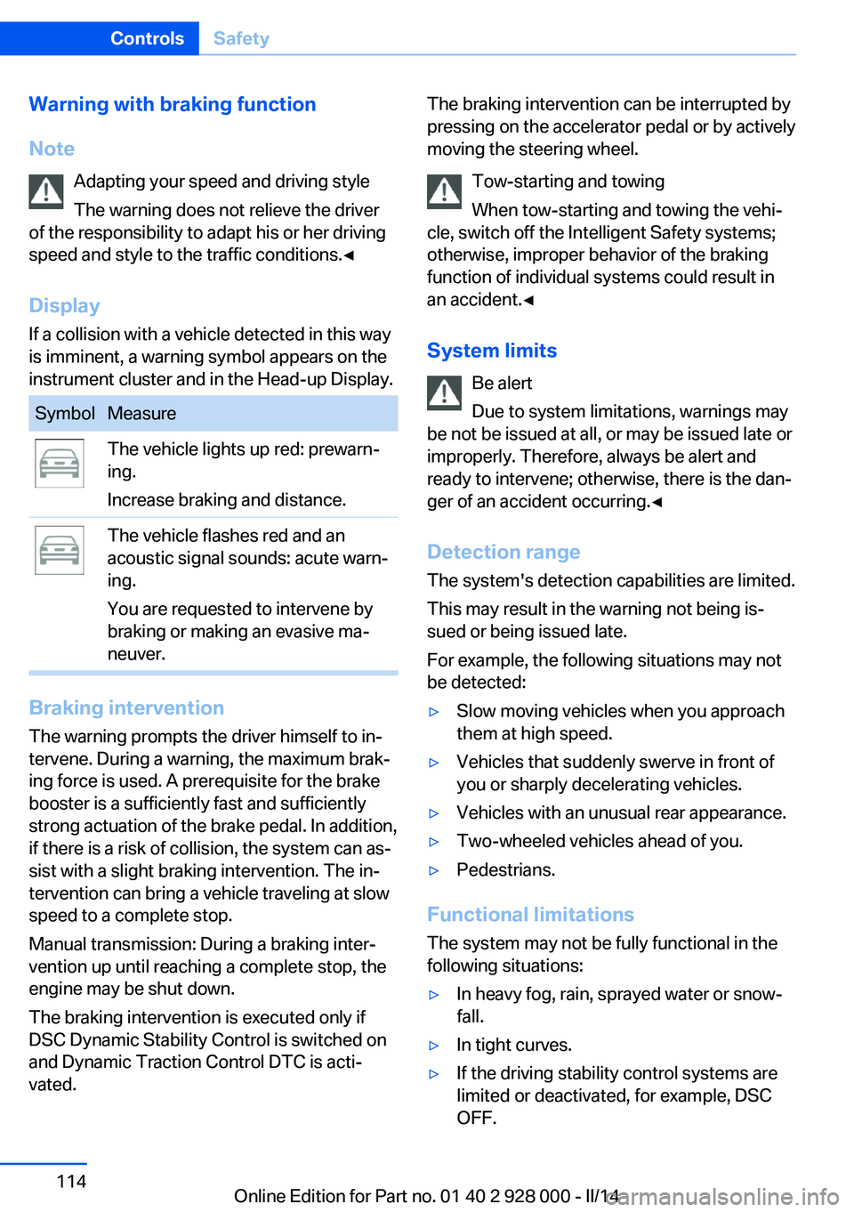
Display If a collision with a vehicle detected in this way
is imminent, a warning symbol appears on the
instrument cluster and in the Head-up Display.SymbolMeasureThe vehicle lights up red: prewarn‐
ing.
Increase braking and distance.The vehicle flashes red and an
acoustic signal sounds: acute warn‐
ing.
You are requested to intervene by
braking or making an evasive ma‐
neuver.
Braking intervention
The warning prompts the driver himself to in‐
tervene. During a warning, the maximum brak‐
ing force is used. A prerequisite for the brake
booster is a sufficiently fast and sufficiently
strong actuation of the brake pedal. In addition,
if there is a risk of collision, the system can as‐
sist with a slight braking intervention. The in‐ tervention can bring a vehicle traveling at slow
speed to a complete stop.
Manual transmission: During a braking inter‐
vention up until reaching a complete stop, the
engine may be shut down.
The braking intervention is executed only if
DSC Dynamic Stability Control is switched on
and Dynamic Traction Control DTC is acti‐
vated.
The braking intervention can be interrupted by
pressing on the accelerator pedal or by actively
moving the steering wheel.
Tow-starting and towing
When tow-starting and towing the vehi‐
cle, switch off the Intelligent Safety systems;
otherwise, improper behavior of the braking
function of individual systems could result in
an accident.◀
System limits Be alert
Due to system limitations, warnings may
be not be issued at all, or may be issued late or
improperly. Therefore, always be alert and
ready to intervene; otherwise, there is the dan‐
ger of an accident occurring.◀
Detection range
The system's detection capabilities are limited.
This may result in the warning not being is‐
sued or being issued late.
For example, the following situations may not
be detected:▷Slow moving vehicles when you approach
them at high speed.▷Vehicles that suddenly swerve in front of
you or sharply decelerating vehicles.▷Vehicles with an unusual rear appearance.▷Two-wheeled vehicles ahead of you.▷Pedestrians.
Functional limitations
The system may not be fully functional in the
following situations:
▷In heavy fog, rain, sprayed water or snow‐
fall.▷In tight curves.▷If the driving stability control systems are
limited or deactivated, for example, DSC
OFF.Seite 114ControlsSafety114
Online Edition for Part no. 01 40 2 928 000 - II/14
Page 116 of 267
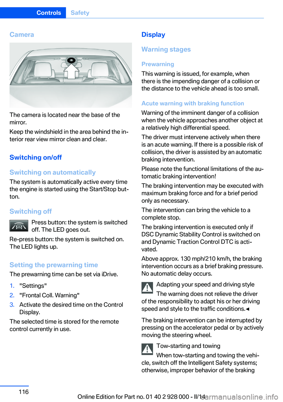
Camera
The camera is located near the base of the
mirror.
Keep the windshield in the area behind the in‐
terior rear view mirror clean and clear.
Switching on/off
Switching on automatically The system is automatically active every time
the engine is started using the Start/Stop but‐
ton.
Switching off Press button: the system is switched
off. The LED goes out.
Re-press button: the system is switched on.
The LED lights up.
Setting the prewarning time The prewarning time can be set via iDrive.
1."Settings"2."Frontal Coll. Warning"3.Activate the desired time on the Control
Display.
The selected time is stored for the remote
control currently in use.
Display
Warning stages
Prewarning
This warning is issued, for example, when there is the impending danger of a collision or
the distance to the vehicle ahead is too small.
Acute warning with braking function
Warning of the imminent danger of a collision
when the vehicle approaches another object at
a relatively high differential speed.
The driver must intervene actively when there
is an acute warning. If there is a possible risk of
collision, the driver is assisted by an automatic
braking intervention.
Please note the functional limitations of the au‐
tomatic braking intervention!
The braking intervention may be executed with
maximum braking force and for a brief period
only as necessary.
The intervention can bring the vehicle to a
complete stop.
The braking intervention is executed only if
DSC Dynamic Stability Control is switched on
and Dynamic Traction Control DTC is acti‐
vated.
Above approx. 130 mph/210 km/h, the braking
intervention occurs as a brief braking pressure.
No automatic delay occurs.
Adapting your speed and driving style
The warning does not relieve the driver
of the responsibility to adapt his or her driving
speed and style to the traffic conditions.◀
The braking intervention can be interrupted by
pressing on the accelerator pedal or by actively
moving the steering wheel.
Tow-starting and towing
When tow-starting and towing the vehi‐
cle, switch off the Intelligent Safety systems;
otherwise, improper behavior of the brakingSeite 116ControlsSafety116
Online Edition for Part no. 01 40 2 928 000 - II/14
Page 117 of 267
function of individual systems could result in
an accident.◀
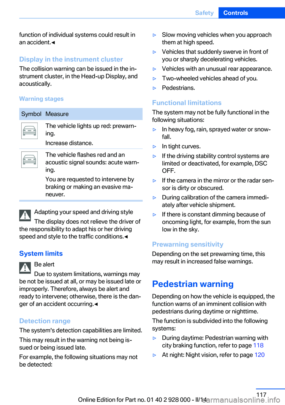
Display in the instrument cluster The collision warning can be issued in the in‐
strument cluster, in the Head-up Display, and
acoustically.
Warning stagesSymbolMeasureThe vehicle lights up red: prewarn‐
ing.
Increase distance.The vehicle flashes red and an
acoustic signal sounds: acute warn‐
ing.
You are requested to intervene by
braking or making an evasive ma‐
neuver.
Adapting your speed and driving style
The display does not relieve the driver of
the responsibility to adapt his or her driving
speed and style to the traffic conditions.◀
System limits Be alert
Due to system limitations, warnings may
be not be issued at all, or may be issued late or
improperly. Therefore, always be alert and
ready to intervene; otherwise, there is the dan‐
ger of an accident occurring.◀
Detection range
The system's detection capabilities are limited.
This may result in the warning not being is‐ sued or being issued late.
For example, the following situations may not
be detected:
▷Slow moving vehicles when you approach
them at high speed.▷Vehicles that suddenly swerve in front of
you or sharply decelerating vehicles.▷Vehicles with an unusual rear appearance.▷Two-wheeled vehicles ahead of you.▷Pedestrians.
Functional limitations
The system may not be fully functional in the
following situations:
▷In heavy fog, rain, sprayed water or snow‐
fall.▷In tight curves.▷If the driving stability control systems are
limited or deactivated, for example, DSC
OFF.▷If the camera in the mirror or the radar sen‐
sor is dirty or obscured.▷During calibration of the camera immedi‐
ately after vehicle shipment.▷If there is constant dimming because of
oncoming light, for example, from the sun
low in the sky.
Prewarning sensitivity
Depending on the set prewarning time, this
may result in increased false warnings.
Pedestrian warning
Depending on how the vehicle is equipped, the
function warns of an imminent collision with
pedestrians during daytime or nighttime.
The function is subdivided into the following
systems:
▷During daytime: Pedestrian warning with
city braking function, refer to page 118▷At night: Night vision, refer to page 120Seite 117SafetyControls117
Online Edition for Part no. 01 40 2 928 000 - II/14