low pressure BMW 535I 2011 F10 Owner's Manual
[x] Cancel search | Manufacturer: BMW, Model Year: 2011, Model line: 535I, Model: BMW 535I 2011 F10Pages: 304, PDF Size: 10.18 MB
Page 71 of 304
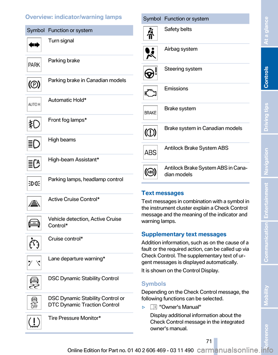
Overview: indicator/warning lamps
Symbol Function or system
Turn signal
Parking brake
Parking brake in Canadian models
Automatic Hold*
Front fog lamps*
High beams
High-beam Assistant*
Parking lamps, headlamp control
Active Cruise Control*
Vehicle detection, Active Cruise
Control*
Cruise control*
Lane departure warning*
DSC Dynamic Stability Control
DSC Dynamic Stability Control or
DTC Dynamic Traction Control
Tire Pressure Monitor* Symbol Function or system
Safety belts
Airbag system
Steering system
Emissions
Brake system
Brake system in Canadian models
Antilock Brake System ABS
Antilock Brake System ABS in Cana‐
dian models
Text messages
Text
messages in combination with a symbol in
the instrument cluster explain a Check Control
message and the meaning of the indicator and
warning lamps.
Supplementary text messages
Addition information, such as on the cause of a
fault or the required action, can be called up via
Check Control. The supplementary text of ur‐
gent messages is displayed automatically.
It is shown on the Control Display.
Symbols
Depending on the Check Control message, the
following functions can be selected.
▷ "Owner's Manual"
Display additional information about the
Check Control message in the integrated
owner's manual.
Seite 71
71Online Edition for Part no. 01 40 2 606 469 - 03 11 490
Reference Mobility Communication Entertainment Navigation Driving tips
Controls At a glance
Page 88 of 304
If the message does not disappear after a repeat
calibration,
have the system checked as soon as
possible.
Unobstructed area of movement
Ensure that the area of movement of the
seats is unobstructed to avoid personal injury or
damage to objects.◀
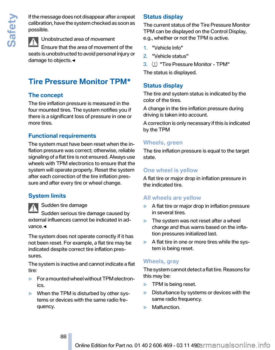
Tire Pressure Monitor TPM*
The concept
The tire inflation pressure is measured in the
four mounted tires. The system notifies you if
there is a significant loss of pressure in one or
more tires.
Functional requirements
The system must have been reset when the in‐
flation pressure was correct; otherwise, reliable
signaling of a flat tire is not ensured. Always use
wheels with TPM electronics to ensure that the
system will operate properly. Reset the system
after each correction of the tire inflation pres‐
sure and after every tire or wheel change.
System limits
Sudden tire damage
Sudden serious tire damage caused by
external influences cannot be indicated in ad‐
vance.◀
The system does not operate correctly if it has
not been reset. For example, a flat tire may be
indicated despite correct tire inflation pres‐
sures.
The system is inactive and cannot indicate a flat
tire:
▷ For a mounted wheel without TPM electron‐
ics.
▷ When the TPM is disturbed by other sys‐
tems or devices with the same radio fre‐
quency. Status display
The
current status of the Tire Pressure Monitor
TPM can be displayed on the Control Display,
e.g., whether or not the TPM is active.
1. "Vehicle Info"
2. "Vehicle status"
3. "Tire Pressure Monitor - TPM"
The status is displayed.
Status display
The tire and system status is indicated by the
color of the tires.
A change in the tire inflation pressure during
driving is taken into account.
A
correction is only necessary if this is indicated
by the TPM
Wheels, green
The tire inflation pressure is equal to the target
state.
One wheel is yellow
A flat tire or major drop in inflation pressure in
the indicated tire.
All wheels are yellow
▷ A flat tire or major drop in inflation pressure
in several tires.
▷ The system was not reset after a wheel
change and thus warns based on the infla‐
tion pressures initialized last.
▷ A flat tire in one or more tires while the sys‐
tem is being reset.
Wheels, gray
The
system cannot detect a flat tire. Reasons for
this may be:
▷ TPM is being reset.
▷ Disturbance by systems or devices with the
same radio frequency.
▷ Malfunction.
Seite 88
88 Online Edition for Part no. 01 40 2 606 469 - 03 11 490
Safety
Page 89 of 304
For Canadian models: additional
information
The status display additionally shows the cur‐
rent tire inflation pressures and tire tempera‐
tures.
When correcting the tire inflation pressures,
note the following:
The tire pressure increases as the tire temper‐
ature increases.
Therefore, only correct the tire inflation pres‐
sure
when the tire is at the ambient temperature.
Compare the displayed tire temperature with
the external temperature in the instrument clus‐
ter.
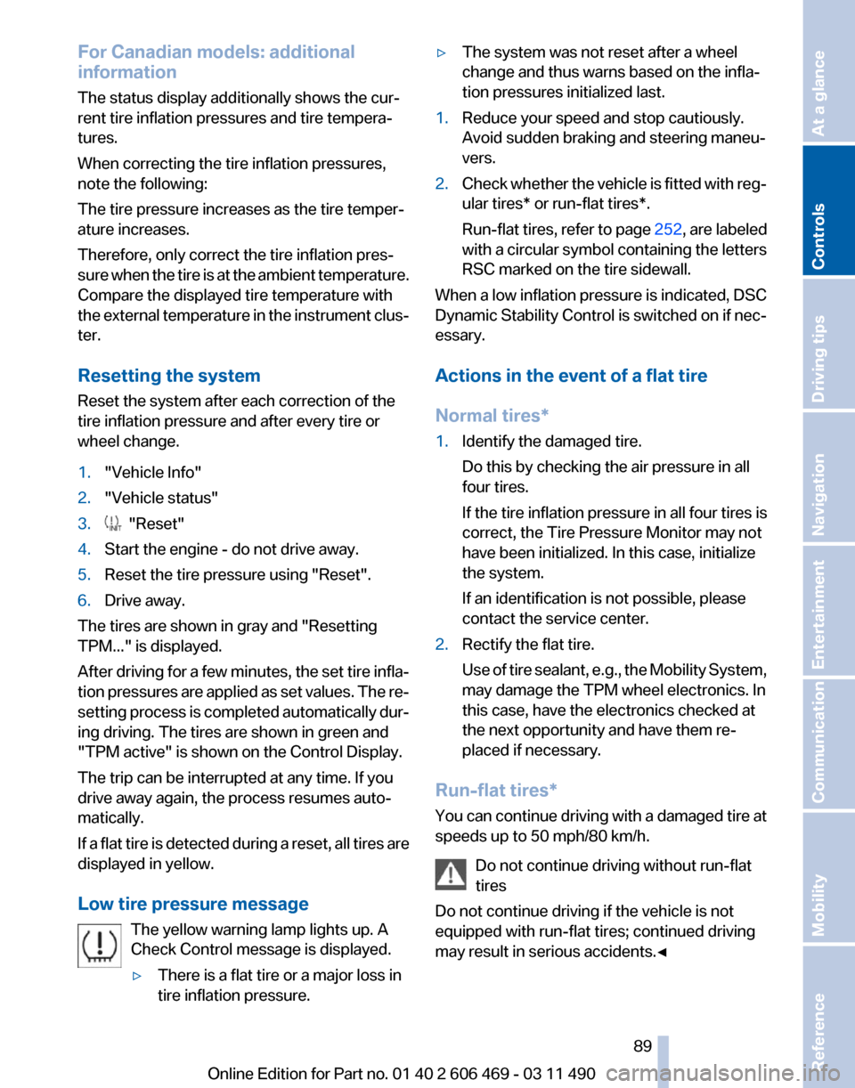
Resetting the system
Reset the system after each correction of the
tire inflation pressure and after every tire or
wheel change.
1. "Vehicle Info"
2. "Vehicle status"
3. "Reset"
4. Start the engine - do not drive away.
5. Reset the tire pressure using "Reset".
6. Drive away.
The tires are shown in gray and "Resetting
TPM..." is displayed.
After
driving for a few minutes, the set tire infla‐
tion pressures are applied as set values. The re‐
setting process is completed automatically dur‐
ing driving. The tires are shown in green and
"TPM active" is shown on the Control Display.
The trip can be interrupted at any time. If you
drive away again, the process resumes auto‐
matically.
If a flat tire is detected during a reset, all tires are
displayed in yellow.
Low tire pressure message
The yellow warning lamp lights up. A
Check Control message is displayed.
▷There is a flat tire or a major loss in
tire inflation pressure. ▷
The system was not reset after a wheel
change and thus warns based on the infla‐
tion pressures initialized last.
1. Reduce your speed and stop cautiously.
Avoid sudden braking and steering maneu‐
vers.
2. Check whether the vehicle is fitted with reg‐
ular tires* or run-flat tires*.
Run-flat
tires, refer to page 252, are labeled
with a circular symbol containing the letters
RSC marked on the tire sidewall.
When a low inflation pressure is indicated, DSC
Dynamic
Stability Control is switched on if nec‐
essary.
Actions in the event of a flat tire
Normal tires*
1. Identify the damaged tire.
Do this by checking the air pressure in all
four tires.
If the tire inflation pressure in all four tires is
correct, the Tire Pressure Monitor may not
have been initialized. In this case, initialize
the system.
If an identification is not possible, please
contact the service center.
2. Rectify the flat tire.
Use
of tire sealant, e.g., the Mobility System,
may damage the TPM wheel electronics. In
this case, have the electronics checked at
the next opportunity and have them re‐
placed if necessary.
Run-flat tires*
You
can continue driving with a damaged tire at
speeds up to 50 mph/80 km/h.
Do not continue driving without run-flat
tires
Do not continue driving if the vehicle is not
equipped with run-flat tires; continued driving
may result in serious accidents.◀ Seite 89
89Online Edition for Part no. 01 40 2 606 469 - 03 11 490
Reference Mobility Communication Entertainment Navigation Driving tips
Controls At a glance
Page 90 of 304
Continued driving with a flat tire
If continuing to drive with a damaged tire:
1.
Avoid sudden braking and steering maneu‐
vers.
2. Do not exceed a speed of 50 mph/80 km/h.
3. Check the air pressure in all four tires at the
next opportunity.
If the tire inflation pressure in all four tires is
correct, the Tire Pressure Monitor may not
have been initialized. In this case, initialize
the system.
Possible driving distance with complete loss of
tire inflation pressure:
The possible driving distance after a loss of tire
inflation pressure depends on the cargo load
and the driving style and conditions.
For a vehicle containing an average load, the
possible driving distance is approx. 50 miles/
80 km.
When the vehicle is driven with a damaged tire,
its handling characteristics change, e.g., re‐
duced lane stability during braking, a longer
braking distance, and altered self-steering
properties. Adjust your driving style accord‐
ingly. Avoid abrupt steering maneuvers or driv‐
ing over obstacles, e.g., curbs, potholes, etc.
Because
the possible driving distance depends
on how the vehicle is used during the trip, the
actual distance may be smaller or greater de‐
pending on the driving speed, road conditions,
external temperature, cargo load, etc.
Continued driving with a flat tire
Drive moderately and do not exceed a
speed of 50 mph/80 km/h.
A loss of tire inflation pressure results in a
change in the handling characteristics, e.g., re‐
duced lane stability during braking, a longer
braking distance and altered self-steering prop‐
erties.◀
Final tire failure
Vibrations or loud noises while driving can
indicate the final failure of the tire. Reduce speed
and stop; otherwise, pieces of the tire could come loose and cause an accident. Do not con‐
tinue
driving, and contact your service center.◀
Message when the system was not
reset
A Check Control message is displayed.
The system detected a wheel change but was
not reset.
Warnings regarding the current tire inflation
pressure are not reliable.
Check the tire inflation pressure and reset the
system.
Malfunction The yellow warning lamp flashes and
then lights up continuously. A Check
Control message is displayed. No flat
tire can be detected.
Display in the following situations:
▷ A wheel without TPM electronics is fitted:
have
the service center check it if necessary.
▷ Malfunction: have the system checked by
your service center.
▷ TPM could not be fully reset. Reset the sys‐
tem again.
▷ Disturbance by systems or devices with the
same
radio frequency: after leaving the area
of the disturbance, the system automatically
becomes active again.
Declaration according to NHTSA/
FMVSS 138 Tire Pressure Monitoring
System
Each tire, including the spare (if provided)
should be checked monthly when cold and in‐
flated
to the inflation pressure recommended by
the vehicle manufacturer on the vehicle placard
or tire inflation pressure label. (If your vehicle has
tires of a different size than the size indicated on
the vehicle placard or tire inflation pressure la‐
bel, you should determine the proper tire infla‐
tion pressure for those tires.) As an added safety
feature, your vehicle has been equipped with a
tire pressure monitoring system (TPMS) that il‐
luminates a low tire pressure telltale when one Seite 90
90 Online Edition for Part no. 01 40 2 606 469 - 03 11 490
Safety
Page 91 of 304
or more of your tires is significantly under-in‐
flated. Accordingly, when the low tire pressure
telltale illuminates, you should stop and check
your tires as soon as possible, and inflate them
to
the proper pressure. Driving on a significantly
under-inflated tire causes the tire to overheat
and can lead to tire failure. Under-inflation also
reduces fuel efficiency and tire tread life, and
may affect the vehicle's handling and stopping
ability. Please note that the TPMS is not a sub‐
stitute for proper tire maintenance, and it is the
driver's responsibility to maintain correct tire
pressure, even if under-inflation has not reached
the level to trigger illumination of the TPMS low
tire pressure telltale. Your vehicle has also been
equipped with a TPMS malfunction indicator to
indicate when the system is not operating prop‐
erly. The TPMS malfunction indicator is com‐
bined with the low tire pressure telltale. When
the system detects a malfunction, the telltale will
flash for approximately one minute and then re‐
main continuously illuminated. This sequence
will continue upon subsequent vehicle start-ups
as long as the malfunction exists. When the mal‐
function indicator is illuminated, the system may
not be able to detect or signal low tire pressure
as intended. TPMS malfunctions may occur for
a variety of reasons, including the installation of
replacement or alternate tires or wheels on the
vehicle that prevent the TPMS from functioning
properly. Always check the TPMS malfunction
telltale after replacing one or more tires or
wheels on your vehicle to ensure that the re‐
placement or alternate tires and wheels allow
the TPMS to continue to function properly.
Lane departure warning*
The concept
This system issues a warning at speeds above
approx. 40 mph/65 km/h if the vehicle is about
to leave the lane on roads with lane markings.
The steering wheel begins vibrating gently.
The system does not provide a warning if the
turn signal is set before leaving the lane. Switching on/off
Press the button.
▷ On: the LED lights up.
▷ Off: the LED goes out.
The system can issue warnings at speeds above
approx. 40 mph/65 km/h.
The state is stored for the remote control cur‐
rently in use.
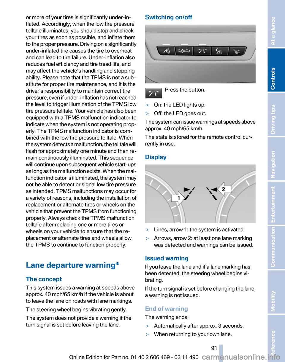
Display ▷
Lines, arrow 1: the system is activated.
▷ Arrows, arrow 2: at least one lane marking
was detected and warnings can be issued.
Issued warning
If you leave the lane and if a lane marking has
been detected, the steering wheel begins vi‐
brating.
If
the turn signal is set before changing the lane,
a warning is not issued.
End of warning
The warning ends:
▷ Automatically after approx. 3 seconds.
▷ When returning to your own lane. Seite 91
91Online Edition for Part no. 01 40 2 606 469 - 03 11 490
Reference Mobility Communication Entertainment Navigation Driving tips
Controls At a glance
Page 112 of 304
Low objects already displayed, e.g., curbs, can
move
into the blind area of the sensors before or
after a continuous tone sounds.
High, protruding objects such as ledges may not
be detected.
False warnings
PDC may issue a warning under the following
conditions even though there is no obstacle
within the detection range:
▷ In heavy rain.
▷ When sensors are very dirty or covered in
ice.
▷ When sensors are covered in snow.
▷ On rough road surfaces.
▷ In large buildings with right angles and
smooth
walls, e.g., in underground garages.
▷ In heavy exhaust.
▷ Due to other ultrasound sources, e.g.,
sweeping machines, high pressure steam
cleaners or neon lights.
Switching on automatically
Select transmission position R with the engine
running.
Switching off automatically
The
system switches off and the LED goes out:
▷ After approx. 160 ft/50 m when driving for‐
ward.
▷ Above approx. 22 mph/36 km/h when driv‐
ing forward.
Switch on the system again if necessary.
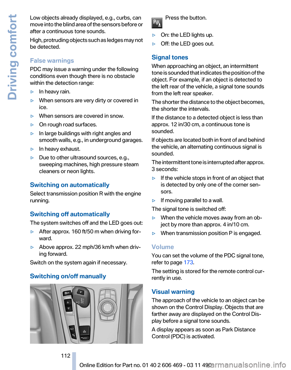
Switching on/off manually Press the button.
▷ On: the LED lights up.
▷ Off: the LED goes out.
Signal tones
When approaching an object, an intermittent
tone
is sounded that indicates the position of the
object. For example, if an object is detected to
the left rear of the vehicle, a signal tone sounds
from the left rear speaker.
The shorter the distance to the object becomes,
the shorter the intervals.
If the distance to a detected object is less than
approx. 12 in/30 cm, a continuous tone is
sounded.
If objects are located both in front of and behind
the vehicle, an alternating continuous signal is
sounded.
The intermittent tone is interrupted after approx.
3 seconds:
▷ If the vehicle stops in front of an object that
is detected by only one of the corner sen‐
sors.
▷ If moving parallel to a wall.
The signal tone is switched off:
▷ When the vehicle moves away from an ob‐
ject by more than approx. 4 in/10 cm.
▷ When transmission position P is engaged.
Volume
You can set the volume of the PDC signal tone,
refer to page 173.
The
setting is stored for the remote control cur‐
rently in use.
Visual warning
The approach of the vehicle to an object can be
shown on the Control Display. Objects that are
farther away are displayed on the Control Dis‐
play before a signal tone sounds.
A display appears as soon as Park Distance
Control (PDC) is activated. Seite 112
112 Online Edition for Part no. 01 40 2 606 469 - 03 11 490
Driving comfort
Page 113 of 304
If the backup camera image was selected last, it
again
appears on the display. To switch to PDC:
1. "Rear view camera" Select the symbol
on the Control Display.
2. Press the controller.
The setting is stored for the remote control cur‐
rently in use.
Zoom view*
On
the left part of the display screen, the vehicle
is shown enlarged. ▷
Forward gear or transmission position D en‐
gaged: front area of the vehicle.
▷ Reverse gear or transmission position R en‐
gaged: rear area of the vehicle.
Display on the Control Display
Switching
on the backup camera via the
iDrive
With PDC activated: "Rear view camera"
The
backup camera image is displayed. The set‐
ting is stored for the remote control currently in
use.
Malfunction
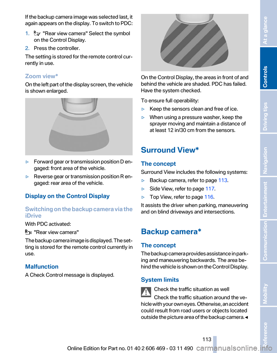
A Check Control message is displayed. On the Control Display, the areas in front of and
behind the vehicle are shaded. PDC has failed.
Have the system checked.
To ensure full operability:
▷
Keep the sensors clean and free of ice.
▷ When using a pressure washer, keep the
sprayer moving and maintain a distance of
at least 12 in/30 cm from the sensors.
Surround View*
The concept
Surround View includes the following systems:
▷ Backup camera, refer to page 113.
▷ Side View, refer to page 117.
▷ Top View, refer to page 116.
It assists the driver when parking, maneuvering
and on blind driveways and intersections.
Backup camera*
The concept
The
backup camera provides assistance in park‐
ing and maneuvering backwards. The area be‐
hind the vehicle is shown on the Control Display.
System limits
Check the traffic situation as well
Check the traffic situation around the ve‐
hicle with your own eyes. Otherwise, an accident
could result from road users or objects located
outside the picture area of the backup camera.◀ Seite 113
113Online Edition for Part no. 01 40 2 606 469 - 03 11 490
Reference Mobility Communication Entertainment Navigation Driving tips
Controls At a glance
Page 122 of 304
To ensure full operability:
▷
Keep the sensors clean and free of ice.
▷ When using a pressure washer, keep the
sprayer moving and maintain a distance of
at least 12 in/30 cm from the sensors.
Night Vision with pedestrian
detection*
The concept
Night
Vision with pedestrian detection is a night
vision system.
An infrared camera records the area in front of
the vehicle and displays the image on the Con‐
trol Display.
The picture is a heat image. The system has an
integrated pedestrian detection function that
detects pedestrians and cyclists. Warm objects
that are similar in shape to human beings are
detected by the system.
Personal responsibility
Night Vision cannot replace the driver's
personal judgment of the visibility conditions
and the traffic situation. The view ahead and the
actual visibility conditions must always be the
basis on which the vehicle speed is adjusted;
otherwise, there is a risk to road safety.◀
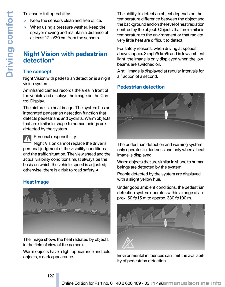
Heat image The image shows the heat radiated by objects
in the field of view of the camera.
Warm objects have a light appearance and cold
objects, a dark appearance. The ability to detect an object depends on the
temperature
difference between the object and
the background and on the level of heat radiation
emitted by the object. Objects that are similar in
temperature to the environment or that radiate
very little heat are difficult to detect.
For safety reasons, when driving at speeds
above approx. 3 mph/5 km/h and in low ambient
light, the image is only displayed when the low
beams are switched on.
A still image is displayed at regular intervals for
a fraction of a second.
Pedestrian detection The pedestrian detection and warning system
only
operates in darkness and only when a heat
image is displayed.
Warm objects that are similar in shape to human
beings are detected by the system.
People detected by the system are displayed
with a slight yellow hue.
Under good ambient conditions, the pedestrian
detection system operates within a range of ap‐
prox. 50 ft/15 m to approx. 330 ft/100 m. Environmental influences can limit the availabil‐
ity of pedestrian detection.
Seite 122
122 Online Edition for Part no. 01 40 2 606 469 - 03 11 490
Driving comfort
Page 148 of 304
Driving in wet conditions
When
roads are wet or there is heavy rain, briefly
exert gentle pressure on the brake pedal every
few miles.
Ensure that this action does not endanger other
road users.
The heat generated in this process helps dry the
brake discs and pads.
In this way braking efficiency will be available
when you need it.
Hills
Drive long or steep downhill gradients in the gear
in which the least braking is required. Otherwise,
the brake system may overheat, resulting in a
reduction in the brake system efficiency.
Manual transmission:
You can increase the engine's braking effect by
shifting down, going all the way to first gear, if
necessary.
Automatic transmission*:
You can increase the engine's braking effect by
shifting down in the manual mode of the auto‐
matic transmission, refer to page 65.
Avoid load on the brakes
Avoid placing excessive load on the brake
system. Light but consistent brake pressure can
lead to high temperatures, brake wear and pos‐
sibly even brake failure.◀
Do not drive in neutral
Do not drive in neutral or with the engine
stopped, as doing so disables engine braking. In
addition, steering and brake assist is unavailable
with the engine stopped.◀
Brake disc corrosion
Corrosion on the brake discs and contamination
on the brake pads are furthered by:
▷ Low mileage.
▷ Extended periods when the vehicle is not
used at all.
▷ Infrequent use of the brakes. Corrosion occurs when the minimum pressure
that must be exerted by the pads during brake
applications to clean the discs is not reached.
Should corrosion form on the brake discs, the
brakes will tend to respond with a pulsating ef‐
fect that generally cannot be corrected.
Condensation
under the parked vehicle
When using the automatic climate control, con‐
densation water develops that exits underneath
the vehicle.
Therefore, traces of condensed water under the
vehicle are normal.
Loading
Overloading the vehicle
To avoid exceeding the approved carrying
capacity of the tires, never overload the vehicle.
Overloading can lead to overheating and in‐
creases the rate at which damage develops in‐
side the tires. This could result in a sudden loss
of tire inflation pressure.◀
No fluids in the trunk
Make sure that fluids do not leak into the
trunk; otherwise, the vehicle may be damaged.◀
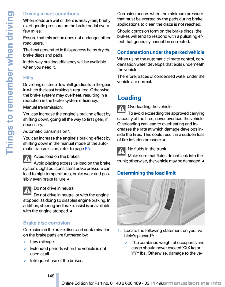
Determining the load limit 1.
Locate the following statement on your ve‐
hicle’s placard*:
▷The combined weight of occupants and
cargo should never exceed XXX kg or
YYY lbs. Otherwise, damage to the ve‐ Seite 148
148 Online Edition for Part no. 01 40 2 606 469 - 03 11 490
Things to remember when driving
Page 151 of 304
Check the tire inflation pressure
regularly
Check
and, if necessary, correct the tire inflation
pressure at least twice a month and before start‐
ing on a long trip.
Low tire inflation pressure increases rolling re‐
sistance and thus raises fuel consumption and
tire wear.
Drive away without delay
Do not wait for the engine to warm up while the
vehicle remains stationary. Start driving right
away, but at moderate engine speeds.
This is the fastest way for the cold engine to
reach its operating temperature.
Look well ahead when driving
Avoid unnecessary acceleration and braking.
By maintaining a suitable distance to the vehicle
driving ahead of you.
Driving smoothly and looking ahead reduces
fuel consumption.
Avoid high engine speeds
Use 1st gear to get the vehicle in motion. Be‐
ginning with 2nd gear, accelerate rapidly. When
accelerating, shift up before reaching high en‐
gine speeds.
When you reach the desired speed, shift into the
highest applicable gear and drive with the en‐
gine speed as low as possible and at a constant
speed.
As a rule: driving at low engine speeds lowers
fuel consumption and reduces wear.
The gear shift indicator* of your vehicle indi‐
cates the most fuel efficient gear.
Use coasting conditions
When approaching a red light, take your foot off
the accelerator and let the vehicle coast to a halt.
On a downhill gradient, take your foot off the ac‐
celerator and let the vehicle roll.
The flow of fuel is interrupted while coasting. Switch off the engine during longer
stops
Switch off the engine during longer stops, e.g.,
at traffic lights, railroad crossings or in traffic
congestion.
Fuel savings are achieved after the vehicle is
switched off for only approx. 4 seconds.
Switch off any functions that are not
currently needed
Functions
such as seat heating and the rear win‐
dow defroster require a lot of energy and con‐
sume additional fuel, especially in city and stop-
and-go traffic.
Therefore, switch off these functions if they are
not actually needed.
Have maintenance carried out
Have vehicles maintained regularly to achieve
optimal vehicle economy and operating life.
Have the maintenance carried out by your serv‐
ice center.
Please also note the BMW Maintenance Sys‐
tem.
Seite 151
151Online Edition for Part no. 01 40 2 606 469 - 03 11 490
Reference Mobility Communication Entertainment Navigation
Driving tips Controls At a glance