mirror BMW 535I GRAN TURISMO 2011 User Guide
[x] Cancel search | Manufacturer: BMW, Model Year: 2011, Model line: 535I GRAN TURISMO, Model: BMW 535I GRAN TURISMO 2011Pages: 297, PDF Size: 8.59 MB
Page 87 of 297
To avoid blinding oncoming traffic, the adaptive
light control directs light towards the front pas‚Äź
senger side when the vehicle is at a standstill.
When
driving in reverse, only the turning lamp is
active.
Self-leveling headlights
The self-leveling headlights feature adapts the
light distribution to the contours of the road.
The light distribution is lowered on hilltops to
avoid blinding oncoming traffic and tilted in de‚Äź
pressions to increase visibility.
Malfunction
A Check Control message is displayed.
Adaptive light control is malfunctioning or has
failed. Have the system checked as soon as pos‚Äź
sible.
High-beam Assistant*
The concept
When the low beams are switched on, this sys‚Äź
tem automatically switches the high beams on
and off. The procedure is controlled by a sensor
on the front of the interior rearview mirror. The
assistant ensures that the high beams are
switched on whenever the traffic situation al‚Äź
lows. The driver can intervene at any time and
switch the high beams on and off as usual.
Activating the High-beam Assistant 1.
Turn the light switch to or .
2. Press the button on the turn signal lever, ar‚Äź
row. The indicator lamp in the instrument
cluster lights up.
When the lights are switched on, the
high beams are switched on and off automati‚Äź
cally.
The system responds to light from oncoming
traffic
and traffic driving ahead of you, and to ad‚Äź
equate illumination, e.g., in towns and cities.
Switching the high beams on and off
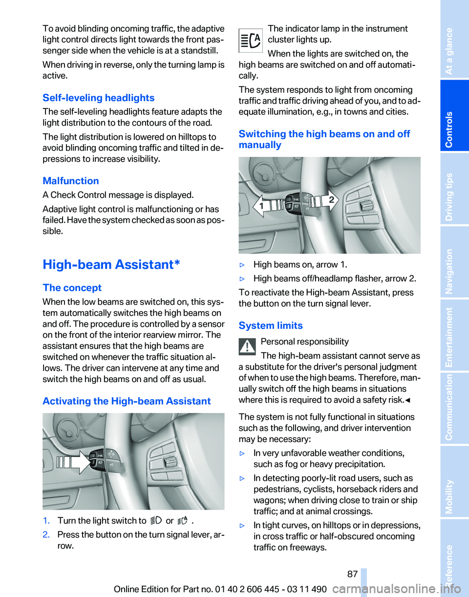
manually ‚Ė∑
High beams on, arrow 1.
‚Ė∑ High beams off/headlamp flasher, arrow 2.
To reactivate the High-beam Assistant, press
the button on the turn signal lever.
System limits
Personal responsibility
The high-beam assistant cannot serve as
a substitute for the driver's personal judgment
of
when to use the high beams. Therefore, man‚Äź
ually switch off the high beams in situations
where this is required to avoid a safety risk.‚óÄ
The system is not fully functional in situations
such as the following, and driver intervention
may be necessary:
‚Ė∑ In very unfavorable weather conditions,
such as fog or heavy precipitation.
‚Ė∑ In detecting poorly-lit road users, such as
pedestrians, cyclists, horseback riders and
wagons; when driving close to train or ship
traffic; and at animal crossings.
‚Ė∑ In tight curves, on hilltops or in depressions,
in cross traffic or half-obscured oncoming
traffic on freeways. Seite 87
87Online Edition for Part no. 01 40 2 606 445 - 03 11 490
Reference Mobility Communication Entertainment Navigation Driving tips
Controls At a glance
Page 88 of 297
‚Ė∑
In poorly-lit towns and cities and in the pres‚Äź
ence of highly reflective signs.
‚Ė∑ At low speeds.
‚Ė∑ When the windshield in front of the interior
rearview mirror is fogged over, dirty or cov‚Äź
ered with stickers, etc.
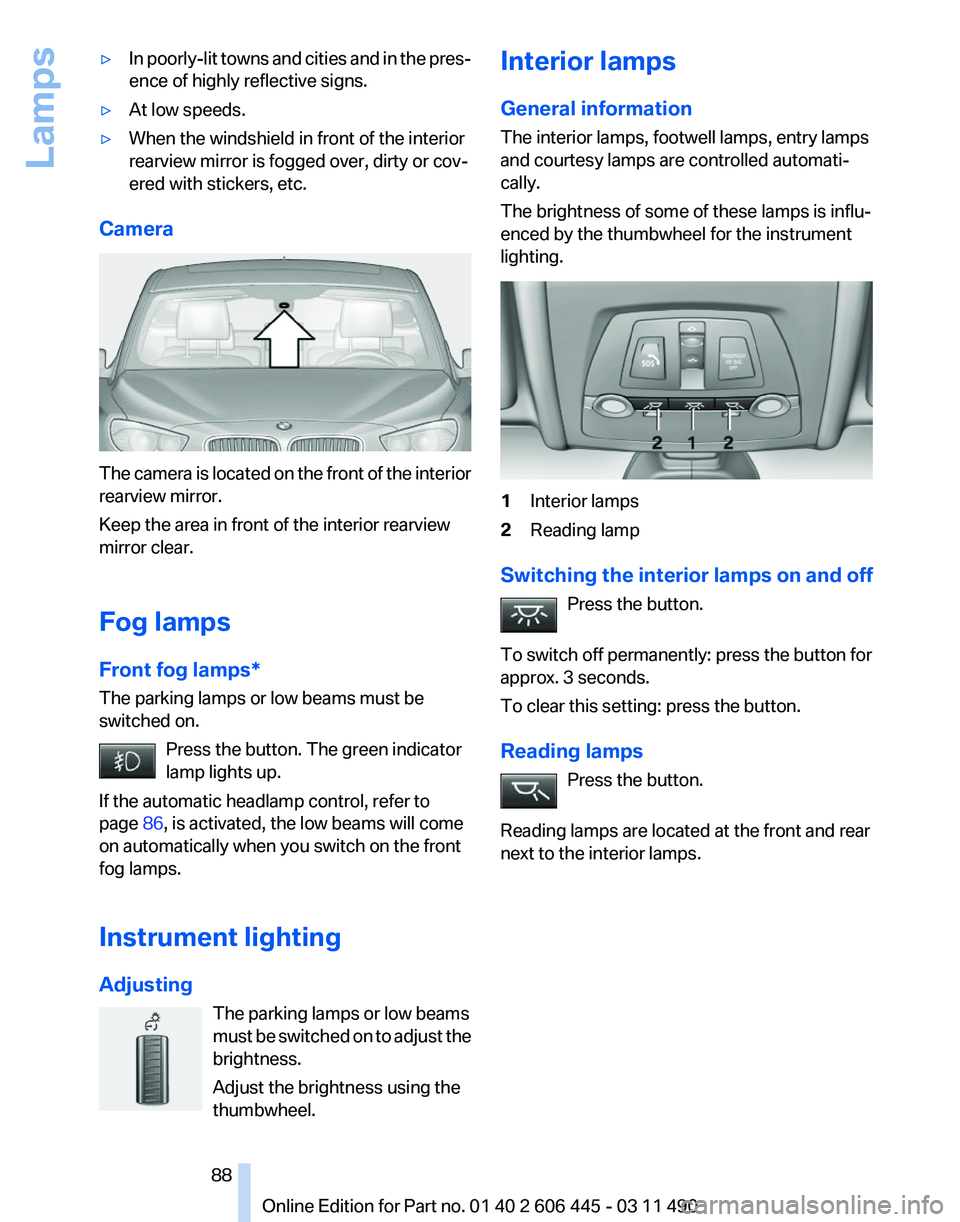
Camera The camera is located on the front of the interior
rearview mirror.
Keep the area in front of the interior rearview
mirror clear.
Fog lamps
Front fog lamps*
The parking lamps or low beams must be
switched on.
Press the button. The green indicator
lamp lights up.
If the automatic headlamp control, refer to
page 86, is activated, the low beams will come
on automatically when you switch on the front
fog lamps.
Instrument lighting
Adjusting
The parking lamps or low beams
must
be switched on to adjust the
brightness.
Adjust the brightness using the
thumbwheel. Interior lamps
General information
The interior lamps, footwell lamps, entry lamps
and courtesy lamps are controlled automati‚Äź
cally.
The brightness of some of these lamps is influ‚Äź
enced by the thumbwheel for the instrument
lighting.
1
Interior lamps
2 Reading lamp
Switching the interior lamps on and off Press the button.
To switch off permanently: press the button for
approx. 3 seconds.
To clear this setting: press the button.
Reading lamps Press the button.
Reading lamps are located at the front and rear
next to the interior lamps. Seite 88
88 Online Edition for Part no. 01 40 2 606 445 - 03 11 490
Lamps
Page 96 of 297
‚Ė∑
When braking hard.
‚Ė∑ When using the turn signal.
System limits Personal responsibility
The system cannot serve as a substitute
for
the driver's personal judgment of the course
of the road and the traffic situation.
In the event of a warning, do not jerk the steering
wheel, as you may lose control of the vehicle.‚óÄ
The system may not be fully functional in the
following situations:
‚Ė∑ In heavy fog, rain or snowfall.
‚Ė∑ In the event of worn, poorly visible, merging,
diverging,
or multiple lane markings such as
in construction areas.
‚Ė∑ When lane markings are covered in snow,
ice, dirt or water.
‚Ė∑ In tight curves or on narrow lanes.
‚Ė∑ When the lane markings are covered by ob‚Äź
jects.
‚Ė∑ When driving very close to the vehicle in
front of you.
‚Ė∑ When driving toward bright lights.
‚Ė∑ When the windshield in front of the interior
rearview mirror is fogged over, dirty or cov‚Äź
ered with stickers, etc.
Malfunctions
Steering wheel vibration
Frequent
activation of the steering wheel vibra‚Äź
tion causes the system to overheat.
This causes the lane departure warning to be‚Äź
come deactivated.
Let the system cool and reactivate it by pressing
the button. Camera
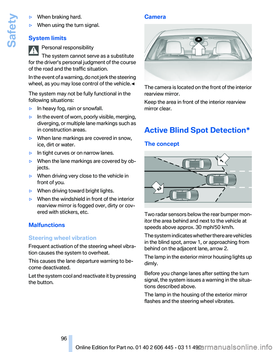
The camera is located on the front of the interior
rearview mirror.
Keep the area in front of the interior rearview
mirror clear.
Active Blind Spot Detection
*
The concept Two radar sensors below the rear bumper mon‚Äź
itor the area behind and next to the vehicle at
speeds above approx. 30 mph/50 km/h.
The
system indicates whether there are vehicles
in the blind spot, arrow 1, or approaching from
behind on the adjacent lane, arrow 2.
The lamp in the exterior mirror housing lights up
dimly.
Before you change lanes after setting the turn
signal, the system issues a warning in the situa‚Äź
tions described above.
The lamp in the housing of the exterior mirror
flashes and the steering wheel vibrates.
Seite 96
96 Online Edition for Part no. 01 40 2 606 445 - 03 11 490
Safety
Page 97 of 297
Switching on/off
Press the button.
‚Ė∑ On: the LED lights up.
‚Ė∑ Off: the LED goes out.
The system can issue warnings at speeds above
approx. 30 mph/50 km/h.
The state is stored for the remote control cur‚Äź
rently in use.
Display Information stage
The dimmed lamp in the mirror housing indi‚Äź
cates when there are vehicles in the blind spot
or approaching from behind.
Warning
If the turn signal is set while a vehicle is in the
critical zone, the steering wheel vibrates briefly
and the lamp in the mirror housing flashes
brightly.
The warning stops when the turn signal is
switched
off, or the other vehicle leaves the crit‚Äź
ical zone. System limits
Personal responsibility
The system cannot serve as a substitute
for the driver's personal judgment of the traffic
situation.
In
the event of a warning, do not jerk the steering
wheel, as you may lose control over the vehi‚Äź
cle.‚óÄ
The system may not be fully functional in the
following situations:
‚Ė∑ When a vehicle is approaching at a speed
much faster than your own.
‚Ė∑ In heavy fog, rain or snowfall.
‚Ė∑ In tight curves or on narrow lanes.
Malfunctions
Steering wheel vibration
Frequent
activation of the steering wheel vibra‚Äź
tion causes the system to overheat.
This causes Active Blind Spot Detection to be‚Äź
come deactivated.
Let the system cool and reactivate it by pressing
the button.
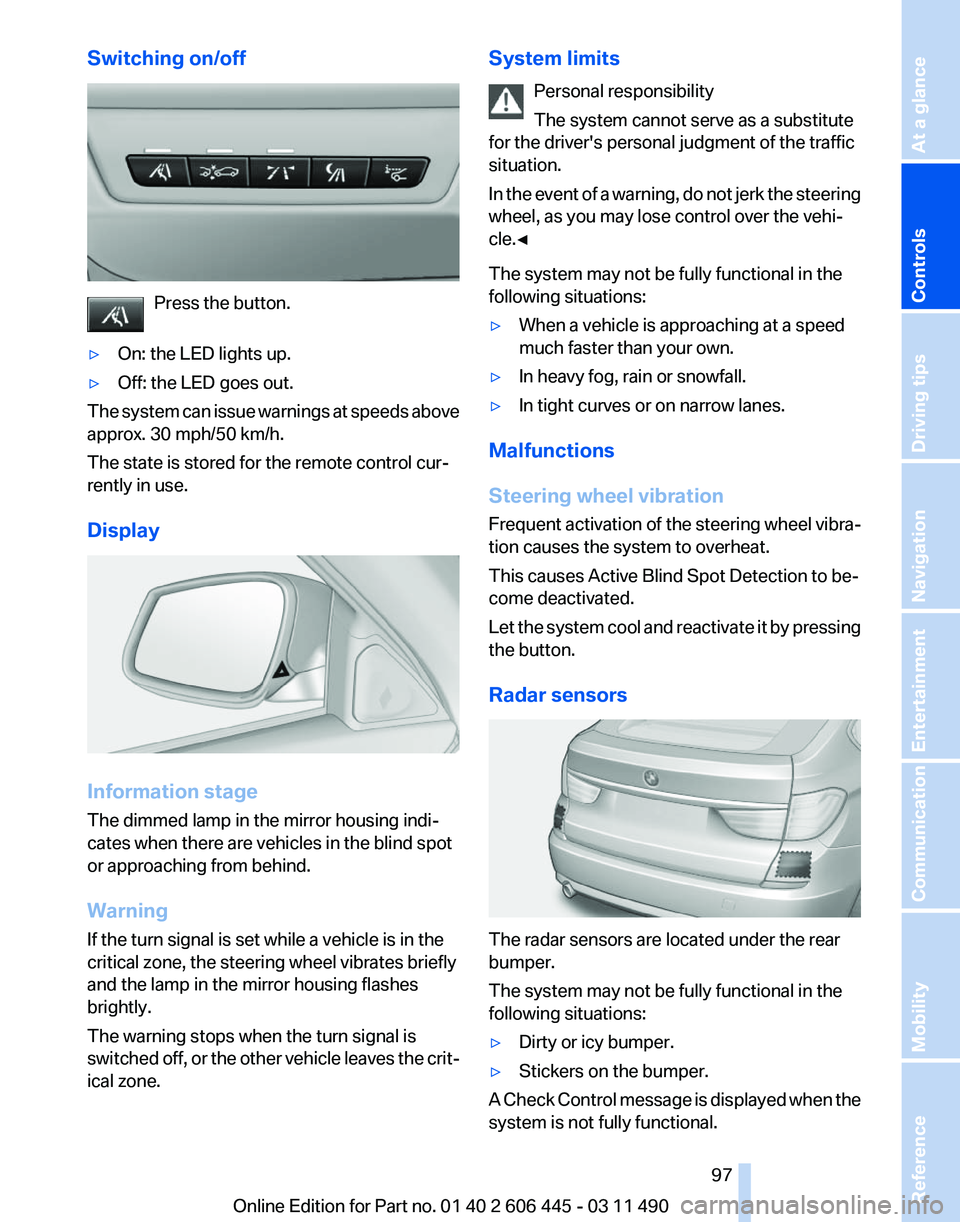
Radar sensors The radar sensors are located under the rear
bumper.
The system may not be fully functional in the
following situations:
‚Ė∑
Dirty or icy bumper.
‚Ė∑ Stickers on the bumper.
A Check Control message is displayed when the
system is not fully functional. Seite 97
97Online Edition for Part no. 01 40 2 606 445 - 03 11 490
Reference Mobility Communication Entertainment Navigation Driving tips
Controls At a glance
Page 117 of 297
If the backup camera image was selected last, it
again
appears on the display. To switch to PDC:
1. "Rear view camera" Select the symbol
on the Control Display.
2. Press the controller.
The setting is stored for the remote control cur‚Äź
rently in use.
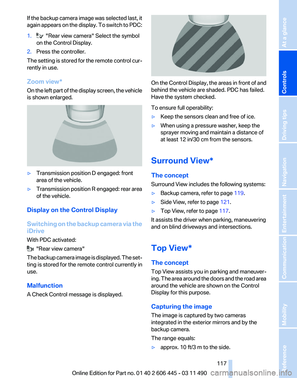
Zoom view*
On
the left part of the display screen, the vehicle
is shown enlarged. ‚Ė∑
Transmission position D engaged: front
area of the vehicle.
‚Ė∑ Transmission position R engaged: rear area
of the vehicle.
Display on the Control Display
Switching
on the backup camera via the
iDrive
With PDC activated: "Rear view camera"
The
backup camera image is displayed. The set‚Äź
ting is stored for the remote control currently in
use.
Malfunction
A Check Control message is displayed. On the Control Display, the areas in front of and
behind the vehicle are shaded. PDC has failed.
Have the system checked.
To ensure full operability:
‚Ė∑
Keep the sensors clean and free of ice.
‚Ė∑ When using a pressure washer, keep the
sprayer moving and maintain a distance of
at least 12 in/30 cm from the sensors.
Surround View*
The concept
Surround View includes the following systems:
‚Ė∑ Backup camera, refer to page 119.
‚Ė∑ Side View, refer to page 121.
‚Ė∑ Top View, refer to page 117.
It assists the driver when parking, maneuvering
and on blind driveways and intersections.
Top View*
The concept
Top
View assists you in parking and maneuver‚Äź
ing. The area around the doors and the road area
around the vehicle are shown on the Control
Display for this purpose.
Capturing the image
The image is captured by two cameras
integrated in the exterior mirrors and by the
backup camera.
The range equals:
‚Ė∑ approx. 10 ft/3 m to the side.
Seite 117
117Online Edition for Part no. 01 40 2 606 445 - 03 11 490
Reference Mobility Communication Entertainment Navigation Driving tips
Controls At a glance
Page 118 of 297
‚Ė∑
approx. 7 ft/2 m to the rear.
In this way, obstacles up to the height of the ex‚Äź
terior mirrors are detected early.
System limits
Top
View cannot be used in the following situa‚Äź
tions:
‚Ė∑ With a door open.
‚Ė∑ With the tailgate open.
‚Ė∑ With an exterior mirror folded in.
‚Ė∑ In poor light.
A Check Control message is displayed in some
of these situations.
Check the traffic situation as well
Check the traffic situation around the ve‚Äź
hicle
with your own eyes. Otherwise, an accident
could result from road users or objects located
outside the picture area of the cameras.‚óÄ
Switching on automatically
Select transmission position R with the engine
running.
The Top View and PDC images are displayed if
the system is switched on via iDrive.
Switching off automatically
The system switches off and the LED goes out:
‚Ė∑ After approx. 160 ft/50 m when driving for‚Äź
ward.
‚Ė∑ Above approx. 22 mph/36 km/h when driv‚Äź
ing forward.
Switch on the system again if necessary.
Switching on/off manually Press the button.
‚Ė∑ On: the LED lights up.
‚Ė∑ Off: the LED goes out.
If Top View is displayed, switch on the backup
camera via the iDrive, refer to page 118.
Visual warning
The
approach of the vehicle to an object can be
shown on the Control Display.
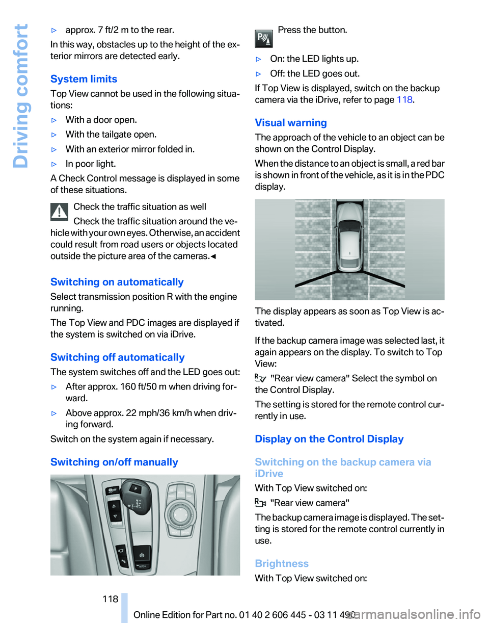
When the distance to an object is small, a red bar
is shown in front of the vehicle, as it is in the PDC
display. The display appears as soon as Top View is ac‚Äź
tivated.
If
the backup camera image was selected last, it
again appears on the display. To switch to Top
View: "Rear view camera" Select the symbol on
the Control Display.
The
setting is stored for the remote control cur‚Äź
rently in use.
Display on the Control Display
Switching on the backup camera via
iDrive
With Top View switched on: "Rear view camera"
The
backup camera image is displayed. The set‚Äź
ting is stored for the remote control currently in
use.
Brightness
With Top View switched on: Seite 118
118 Online Edition for Part no. 01 40 2 606 445 - 03 11 490
Driving comfort
Page 119 of 297
1. "Brightness"
2. Turn the controller until the desired setting
is reached and press the controller.
Contrast
With Top View switched on:
1. "Contrast"
2. Turn the controller until the desired setting
is reached and press the controller.
Displaying the turning circle and
pathway lines
‚Ė∑ The static, red turning circle line shows the
space needed to the side of the vehicle
when the steering wheel is turned all the
way.
‚Ė∑ The variable, green pathway line assists you
in assessing the amount of space actually
needed to the side of the vehicle.
The pathway line is dependent on the cur‚Äź
rent steering angle and is continuously ad‚Äź
justed with the steering wheel movement. "Parking aid lines"
Turning circle and pathway lines are displayed.
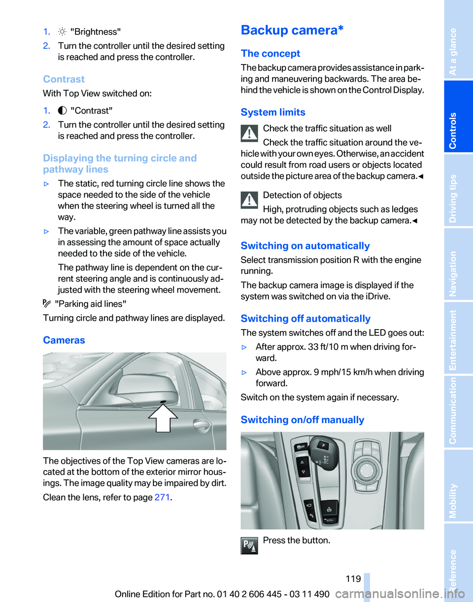
Cameras The objectives of the Top View cameras are lo‚Äź
cated at the bottom of the exterior mirror hous‚Äź
ings.
The image quality may be impaired by dirt.
Clean the lens, refer to page 271.Backup camera*
The concept
The
backup camera provides assistance in park‚Äź
ing and maneuvering backwards. The area be‚Äź
hind the vehicle is shown on the Control Display.
System limits
Check the traffic situation as well
Check the traffic situation around the ve‚Äź
hicle with your own eyes. Otherwise, an accident
could result from road users or objects located
outside the picture area of the backup camera.‚óÄ
Detection of objects
High, protruding objects such as ledges
may not be detected by the backup camera.‚óÄ
Switching on automatically
Select transmission position R with the engine
running.
The backup camera image is displayed if the
system was switched on via the iDrive.
Switching off automatically
The system switches off and the LED goes out:
‚Ė∑ After approx. 33 ft/10 m when driving for‚Äź
ward.
‚Ė∑ Above approx. 9 mph/15 km/h when driving
forward.
Switch on the system again if necessary.
Switching on/off manually Press the button. Seite 119
119Online Edition for Part no. 01 40 2 606 445 - 03 11 490
Reference Mobility Communication Entertainment Navigation Driving tips
Controls At a glance
Page 134 of 297
To do so:
‚Ė∑
Read the instructions of the hand-held
transmitter.
‚Ė∑ Press the memory button of the universal
remote control for an extended period.
If the LED flashes rapidly for a brief period and
then lights up continuously for approx. 2 sec‚Äź
onds, the hand-held transmitter is equipped
with an alternating code system.
In this case, program the memory buttons as
described under Alternating-code hand-held
transmitters.
Alternating-code hand-held
transmitters
Please obtain information on synchronizing the
device
in the operating manual of the device be‚Äź
ing set up.
Programming will be easier with the aid of a sec‚Äź
ond person.
1. Park the vehicle within range of the remote-
controlled device.
2. Program the universal remote control as de‚Äź
scribed above under Fixed-code hand-held
transmitters.
3. Press and hold the programmed button on
the
interior rearview mirror for approx. 5 sec‚Äź
onds until the device to be adjusted is acti‚Äź
vated.
If the device does not become activated,
press and hold the button and watch the
LED:
‚Ė∑ If the LED lights up continuously, the
programming is completed. The device
should
become activated when the but‚Äź
ton is pressed briefly.
‚Ė∑ If the LED flashes for approx. 2 seconds
and then lights up continuously, con‚Äź
tinue the programming procedure be‚Äź
ginning with step 4.
4. Locate the button on the receiver of the de‚Äź
vice to be set, e.g., on the drive. 5.
Press the button on the receiver of the de‚Äź
vice
to be set. You have approx. 30 seconds
for the next step.
6. Press the programmed memory button of
the universal remote control three times.
The device can be operated when the engine is
running or the ignition is switched on.
Reassigning individual programs
1. Switch on the ignition.
2. Hold the hand-held transmitter a distance of
approx.
2 to 8 in/5 to 20 cm from the memory
buttons.
3. Press the memory button of the universal
remote control.
4. If the LED flashes slowly after approx.
20 seconds, press the transmit button on
the hand-held transmitter.
5. Release both buttons when the LED flashes
rapidly.
If
the LED does not flash rapidly after approx.
15 seconds, change the distance and repeat
the step.
Deleting all stored programs
Press the left and right memory buttons for ap‚Äź
prox. 20 seconds until the LED flashes rapidly.
All stored programs are deleted.
The programs cannot be deleted individually.
Seite 134
134 Online Edition for Part no. 01 40 2 606 445 - 03 11 490
Interior equipment
Page 150 of 297
Attachment
Follow the installation instructions of the roof
rack.
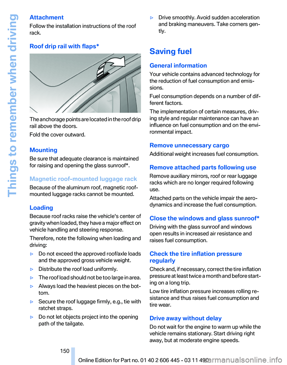
Roof drip rail with flaps
*The anchorage points are located in the roof drip
rail above the doors.
Fold the cover outward.
Mounting
Be sure that adequate clearance is maintained
for raising and opening the
glass sunroof*.
Magnetic roof-mounted luggage rack
Because of the aluminum roof, magnetic roof-
mounted luggage racks cannot be mounted.
Loading
Because roof racks raise the vehicle's center of
gravity when loaded, they have a major effect on
vehicle handling and steering response.
Therefore, note the following when loading and
driving:
‚Ė∑ Do not exceed the approved roof/axle loads
and the approved gross vehicle weight.
‚Ė∑ Distribute the roof load uniformly.
‚Ė∑ The roof load should not be too large in area.
‚Ė∑ Always load the heaviest pieces on the bot‚Äź
tom.
‚Ė∑ Secure the roof luggage firmly, e.g., tie with
ratchet straps.
‚Ė∑ Do not let objects project into the opening
path of the tailgate. ‚Ė∑
Drive smoothly. Avoid sudden acceleration
and braking maneuvers. Take corners gen‚Äź
tly.
Saving fuel
General information
Your vehicle contains advanced technology for
the reduction of fuel consumption and emis‚Äź
sions.
Fuel consumption depends on a number of dif‚Äź
ferent factors.
The implementation of certain measures, driv‚Äź
ing style and regular maintenance can have an
influence on fuel consumption and on the envi‚Äź
ronmental impact.
Remove unnecessary cargo
Additional weight increases fuel consumption.
Remove attached parts following use
Remove auxiliary mirrors, roof or rear luggage
racks which are no longer required following
use.
Attached parts on the vehicle impair the aero‚Äź
dynamics and increase the fuel consumption.
Close the windows and glass sunroof
*
Driving with the glass sunroof and windows
open results in increased air resistance and
raises fuel consumption.
Check the tire inflation pressure
regularly
Check and, if necessary, correct the tire inflation
pressure at least twice a month and before start‚Äź
ing on a long trip.
Low tire inflation pressure increases rolling re‚Äź
sistance and thus raises fuel consumption and
tire wear.
Drive away without delay
Do not wait for the engine to warm up while the
vehicle remains stationary. Start driving right
away, but at moderate engine speeds.
Seite 150
150 Online Edition for Part no. 01 40 2 606 445 - 03 11 490
Things to remember when driving
Page 219 of 297
Adjusting the volume
Turn the knob during an announcement.
‚Ė∑
The volume remains constant even if the
volume of other audio sources is changed.
‚Ė∑ The volume is stored for the remote control
currently in use.
Notes
Do not use the voice operation to initiate an
Emergency
Request. In stressful situations, the
voice and vocal pitch can change. This can un‚Äź
necessarily delay the establishment of a tele‚Äź
phone connection.
Instead, use the SOS button*, refer to
page 264, in the vicinity of the interior mirror.
Environmental conditions
‚Ė∑ Say the commands, numbers, and letters
smoothly and with normal volume, empha‚Äź
sis, and speed.
‚Ė∑ Always say commands in the language of
the system. The language for the mobile
phone voice operation is preset and cannot
be changed in the Control Display.
‚Ė∑ Keep the doors, windows, and glass sun‚Äź
roof* closed to prevent noise interference.
‚Ė∑ Avoid making other noise in the vehicle
while speaking.
Snap-in adapter*
Installation position
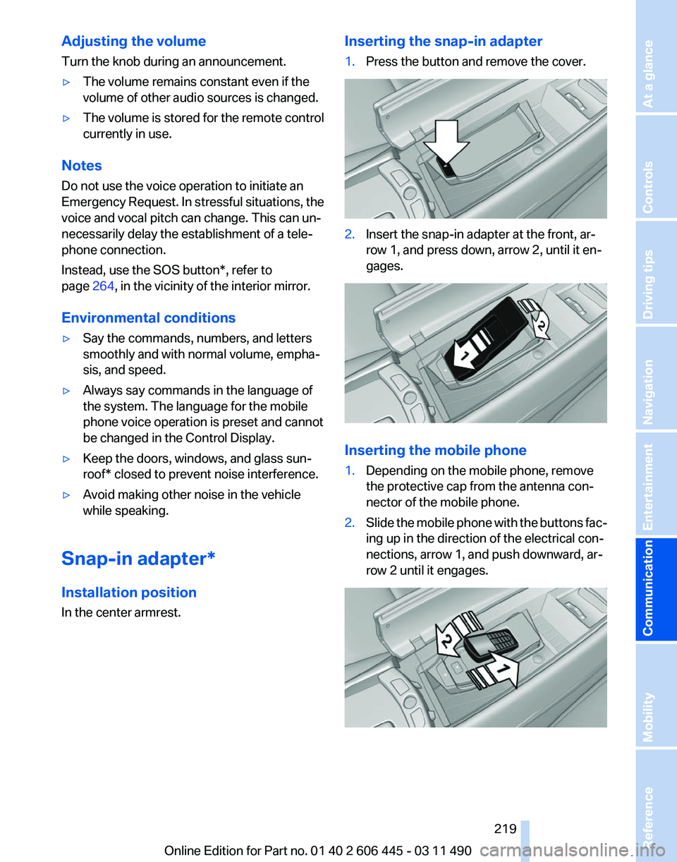
In the center armrest. Inserting the snap-in adapter
1.
Press the button and remove the cover. 2.
Insert the snap-in adapter at the front, ar‚Äź
row 1, and press down, arrow 2, until it en‚Äź
gages. Inserting the mobile phone
1.
Depending on the mobile phone, remove
the protective cap from the antenna con‚Äź
nector of the mobile phone.
2. Slide the mobile phone with the buttons fac‚Äź
ing up in the direction of the electrical con‚Äź
nections, arrow 1, and push downward, ar‚Äź
row 2 until it engages. Seite 219
219Online Edition for Part no. 01 40 2 606 445 - 03 11 490
Reference Mobility
Communication Entertainment Navigation Driving tips Controls At a glance