rear view mirror BMW 535I GRAN TURISMO 2012 Owners Manual
[x] Cancel search | Manufacturer: BMW, Model Year: 2012, Model line: 535I GRAN TURISMO, Model: BMW 535I GRAN TURISMO 2012Pages: 321, PDF Size: 12.7 MB
Page 44 of 321
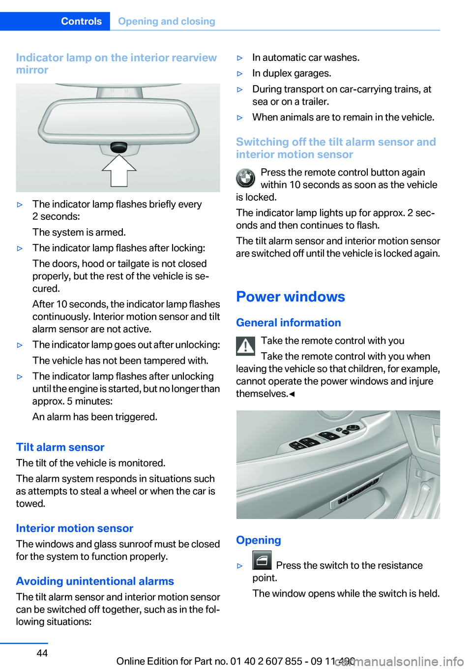
Indicator lamp on the interior rearview
mirror▷The indicator lamp flashes briefly every
2 seconds:
The system is armed.▷The indicator lamp flashes after locking:
The doors, hood or tailgate is not closed
properly, but the rest of the vehicle is se‐
cured.
After 10 seconds, the indicator lamp flashes
continuously. Interior motion sensor and tilt
alarm sensor are not active.▷The indicator lamp goes out after unlocking:
The vehicle has not been tampered with.▷The indicator lamp flashes after unlocking
until the engine is started, but no longer than
approx. 5 minutes:
An alarm has been triggered.
Tilt alarm sensor
The tilt of the vehicle is monitored.
The alarm system responds in situations such
as attempts to steal a wheel or when the car is
towed.
Interior motion sensor
The windows and glass sunroof must be closed
for the system to function properly.
Avoiding unintentional alarms
The tilt alarm sensor and interior motion sensor
can be switched off together, such as in the fol‐
lowing situations:
▷In automatic car washes.▷In duplex garages.▷During transport on car-carrying trains, at
sea or on a trailer.▷When animals are to remain in the vehicle.
Switching off the tilt alarm sensor and
interior motion sensor
Press the remote control button again
within 10 seconds as soon as the vehicle
is locked.
The indicator lamp lights up for approx. 2 sec‐
onds and then continues to flash.
The tilt alarm sensor and interior motion sensor
are switched off until the vehicle is locked again.
Power windows
General information Take the remote control with you
Take the remote control with you when
leaving the vehicle so that children, for example,
cannot operate the power windows and injure
themselves.◀
Opening
▷ Press the switch to the resistance
point.
The window opens while the switch is held.
Seite 44ControlsOpening and closing44
Online Edition for Part no. 01 40 2 607 855 - 09 11 490
Page 61 of 321
Deactivating
Slide the mirror changeover switch to the pas‐
senger's side mirror position.
Fold in and out Press the button.
Possible up to approx. 15 mph/20 km/h.
For example, this is advantageous▷In car washes.▷In narrow streets.▷For folding back mirrors that were folded
away manually.
Mirrors that were folded in are folded out auto‐
matically at a speed of approx. 25 mph/40 km/h.
Fold in the mirror in a car wash
Before entering an automatic car wash,
fold in the exterior mirrors by hand or with the
button; otherwise, they could be damaged, de‐
pending on the width of the vehicle.◀
Automatic heating
Both exterior mirrors are automatically heated
whenever the engine is running.
Automatic dimming feature
Both exterior mirrors are automatically dimmed.
Photocells are used for control in the Interior rear
view mirror, refer to page 61.
Interior rearview mirror
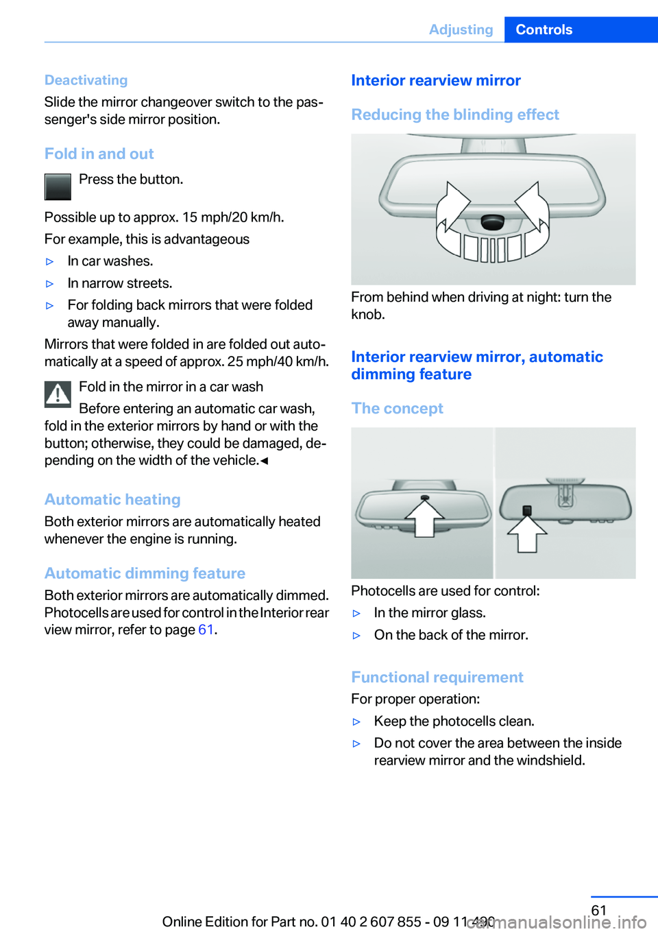
Reducing the blinding effect
From behind when driving at night: turn the
knob.
Interior rearview mirror, automatic
dimming feature
The concept
Photocells are used for control:
▷In the mirror glass.▷On the back of the mirror.
Functional requirement
For proper operation:
▷Keep the photocells clean.▷Do not cover the area between the inside
rearview mirror and the windshield.Seite 61AdjustingControls61
Online Edition for Part no. 01 40 2 607 855 - 09 11 490
Page 73 of 321
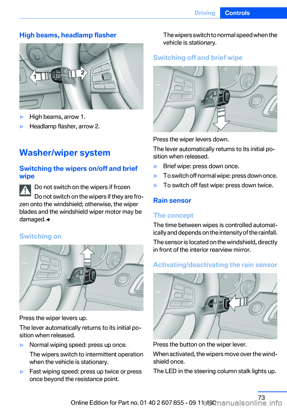
High beams, headlamp flasher▷High beams, arrow 1.▷Headlamp flasher, arrow 2.
Washer/wiper system
Switching the wipers on/off and brief
wipe
Do not switch on the wipers if frozen
Do not switch on the wipers if they are fro‐
zen onto the windshield; otherwise, the wiper
blades and the windshield wiper motor may be
damaged.◀
Switching on
Press the wiper levers up.
The lever automatically returns to its initial po‐
sition when released.
▷Normal wiping speed: press up once.
The wipers switch to intermittent operation
when the vehicle is stationary.▷Fast wiping speed: press up twice or press
once beyond the resistance point.The wipers switch to normal speed when the
vehicle is stationary.
Switching off and brief wipe
Press the wiper levers down.
The lever automatically returns to its initial po‐
sition when released.
▷Brief wipe: press down once.▷To switch off normal wipe: press down once.▷To switch off fast wipe: press down twice.
Rain sensor
The concept
The time between wipes is controlled automat‐
ically and depends on the intensity of the rainfall.
The sensor is located on the windshield, directly
in front of the interior rearview mirror.
Activating/deactivating the rain sensor
Press the button on the wiper lever.
When activated, the wipers move over the wind‐
shield once.
The LED in the steering column stalk lights up.
Seite 73DrivingControls73
Online Edition for Part no. 01 40 2 607 855 - 09 11 490
Page 91 of 321
Adaptive light control
The concept
Adaptive light control is a variable headlamp
control system that enables dynamic illumina‐
tion of the road surface.
Depending on the steering angle and other pa‐
rameters, the light from the headlamp follows
the course of the road.
In tight curves, e.g., on mountainous roads or
when turning, an additional, corner-illuminating
lamp is switched on that lights up the inside of
the curve when the vehicle is moving below a
certain speed.
Activating
Switch position
with the ignition switched
on.
The turning lamps are automatically switched
on depending on the steering angle or the use
of turn signals.
To avoid blinding oncoming traffic, the Adaptive
Light Control directs light towards the front pas‐
senger side when the vehicle is at a standstill.
When driving in reverse, only the turning lamp is
active.
Self-leveling headlights
The self-leveling headlights feature adapts the
light distribution to the contours of the road.
The light distribution is lowered on hilltops to
avoid blinding oncoming traffic and tilted in de‐
pressions to increase visibility.
Malfunction
A Check Control message is displayed.
Adaptive light control is malfunctioning or has
failed. Have the system checked as soon as pos‐
sible.
High-beam Assistant
The concept
When the low beams are switched on, this sys‐
tem automatically switches the high beams on
and off. The procedure is controlled by a sensor
on the front of the interior rearview mirror. The
assistant ensures that the high beams are
switched on whenever the traffic situation al‐
lows. The driver can intervene at any time and
switch the high beams on and off as usual.
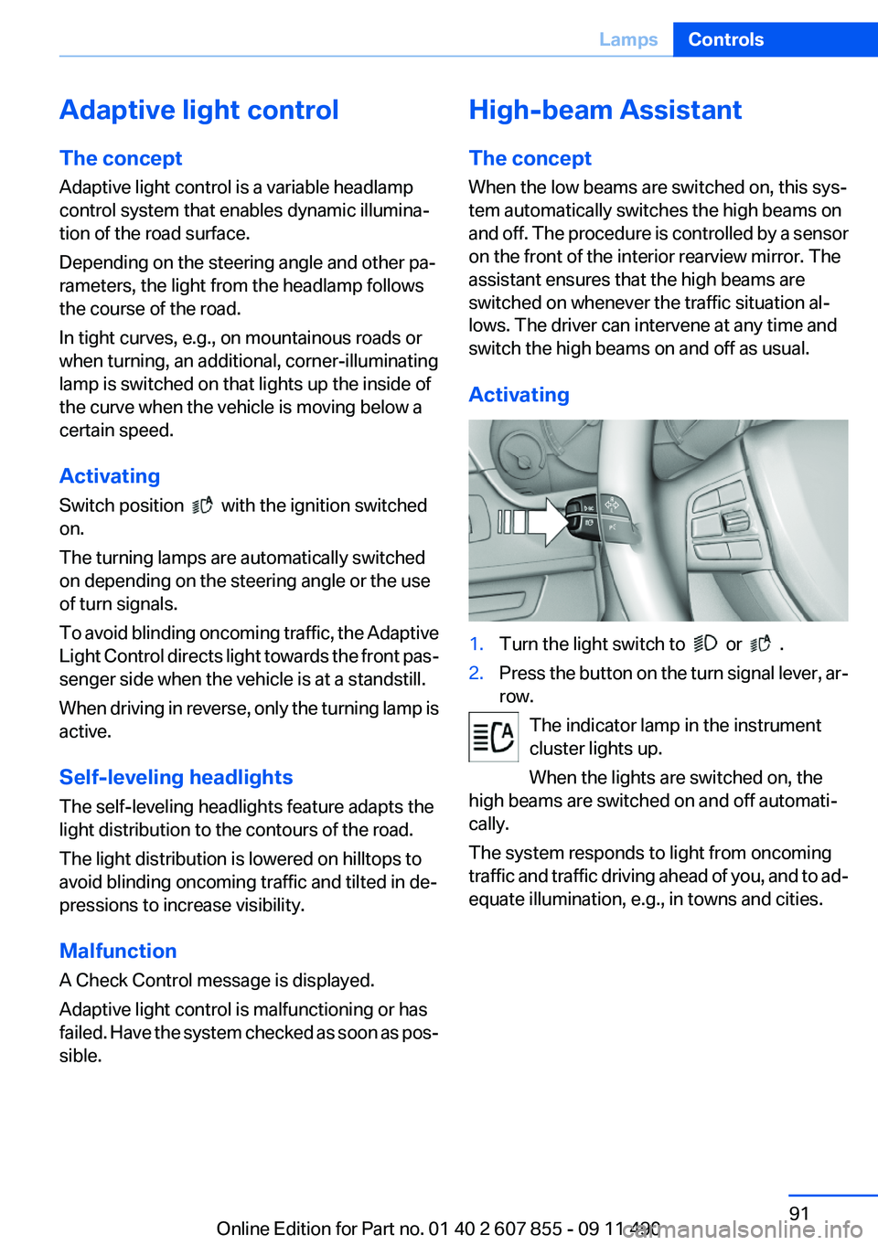
Activating1.Turn the light switch to or .2.Press the button on the turn signal lever, ar‐
row.
The indicator lamp in the instrument
cluster lights up.
When the lights are switched on, the
high beams are switched on and off automati‐
cally.
The system responds to light from oncoming
traffic and traffic driving ahead of you, and to ad‐
equate illumination, e.g., in towns and cities.
Seite 91LampsControls91
Online Edition for Part no. 01 40 2 607 855 - 09 11 490
Page 92 of 321
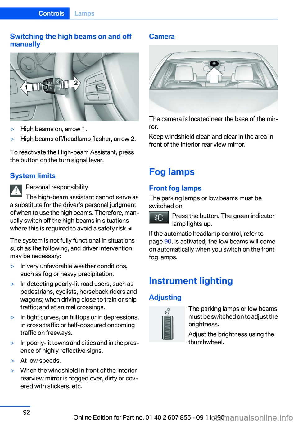
Switching the high beams on and off
manually▷High beams on, arrow 1.▷High beams off/headlamp flasher, arrow 2.
To reactivate the High-beam Assistant, press
the button on the turn signal lever.
System limits Personal responsibility
The high-beam assistant cannot serve as
a substitute for the driver's personal judgment
of when to use the high beams. Therefore, man‐
ually switch off the high beams in situations
where this is required to avoid a safety risk.◀
The system is not fully functional in situations
such as the following, and driver intervention
may be necessary:
▷In very unfavorable weather conditions,
such as fog or heavy precipitation.▷In detecting poorly-lit road users, such as
pedestrians, cyclists, horseback riders and
wagons; when driving close to train or ship
traffic; and at animal crossings.▷In tight curves, on hilltops or in depressions,
in cross traffic or half-obscured oncoming
traffic on freeways.▷In poorly-lit towns and cities and in the pres‐
ence of highly reflective signs.▷At low speeds.▷When the windshield in front of the interior
rearview mirror is fogged over, dirty or cov‐
ered with stickers, etc.Camera
The camera is located near the base of the mir‐
ror.
Keep windshield clean and clear in the area in
front of the interior rear view mirror.
Fog lamps
Front fog lamps
The parking lamps or low beams must be
switched on.
Press the button. The green indicator
lamp lights up.
If the automatic headlamp control, refer to
page 90, is activated, the low beams will come
on automatically when you switch on the front
fog lamps.
Instrument lighting
Adjusting The parking lamps or low beams
must be switched on to adjust the
brightness.
Adjust the brightness using the
thumbwheel.
Seite 92ControlsLamps92
Online Edition for Part no. 01 40 2 607 855 - 09 11 490
Page 103 of 321
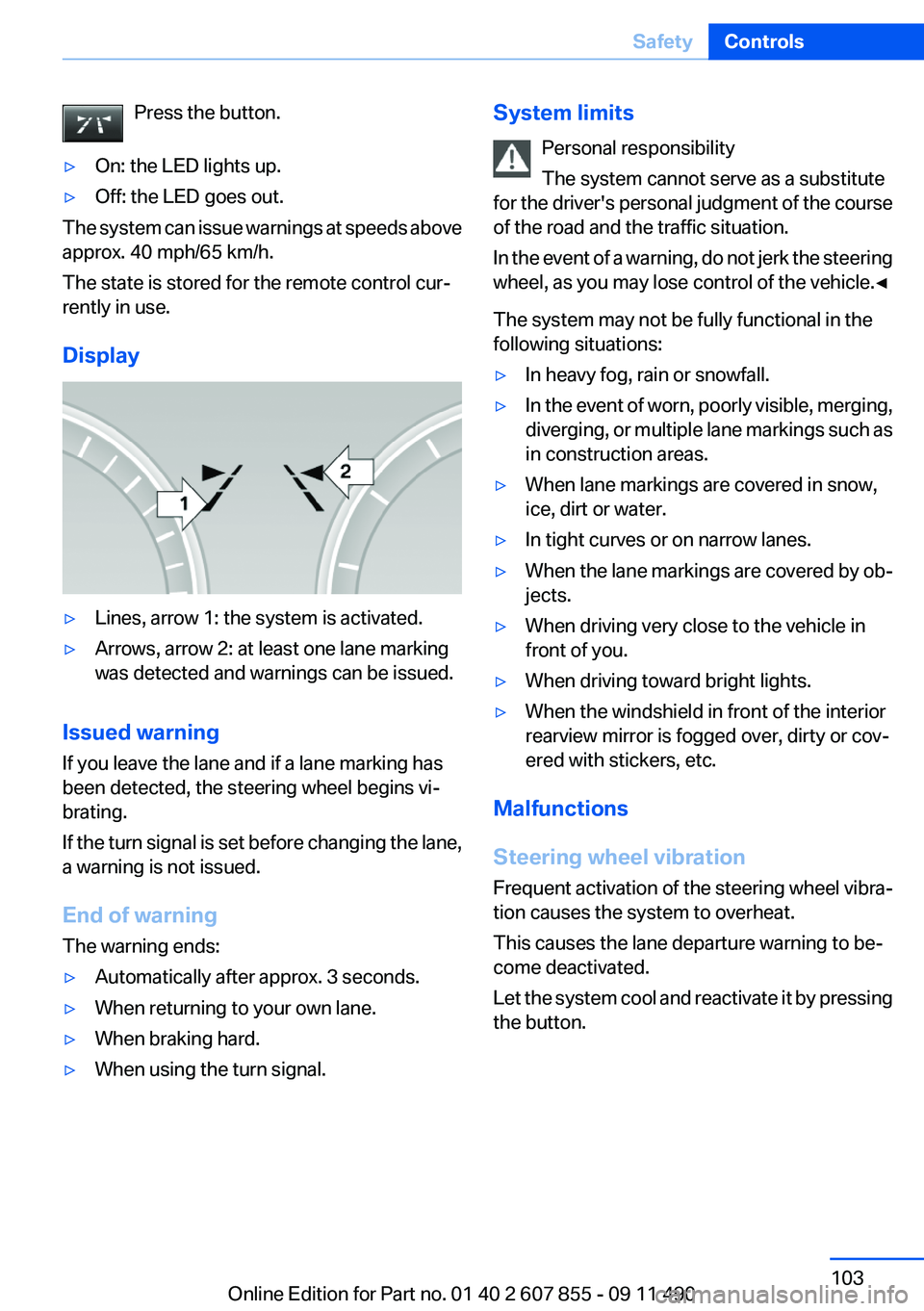
Press the button.▷On: the LED lights up.▷Off: the LED goes out.
The system can issue warnings at speeds above
approx. 40 mph/65 km/h.
The state is stored for the remote control cur‐
rently in use.
Display
▷Lines, arrow 1: the system is activated.▷Arrows, arrow 2: at least one lane marking
was detected and warnings can be issued.
Issued warning
If you leave the lane and if a lane marking has
been detected, the steering wheel begins vi‐
brating.
If the turn signal is set before changing the lane,
a warning is not issued.
End of warning
The warning ends:
▷Automatically after approx. 3 seconds.▷When returning to your own lane.▷When braking hard.▷When using the turn signal.System limits
Personal responsibility
The system cannot serve as a substitute
for the driver's personal judgment of the course
of the road and the traffic situation.
In the event of a warning, do not jerk the steering
wheel, as you may lose control of the vehicle.◀
The system may not be fully functional in the
following situations:▷In heavy fog, rain or snowfall.▷In the event of worn, poorly visible, merging,
diverging, or multiple lane markings such as
in construction areas.▷When lane markings are covered in snow,
ice, dirt or water.▷In tight curves or on narrow lanes.▷When the lane markings are covered by ob‐
jects.▷When driving very close to the vehicle in
front of you.▷When driving toward bright lights.▷When the windshield in front of the interior
rearview mirror is fogged over, dirty or cov‐
ered with stickers, etc.
Malfunctions
Steering wheel vibration
Frequent activation of the steering wheel vibra‐
tion causes the system to overheat.
This causes the lane departure warning to be‐
come deactivated.
Let the system cool and reactivate it by pressing
the button.
Seite 103SafetyControls103
Online Edition for Part no. 01 40 2 607 855 - 09 11 490
Page 104 of 321
Camera
The camera is located near the base of the mir‐
ror.
Keep windshield clean and clear in the area in
front of the interior rear view mirror.
Active Blind Spot Detection
The concept
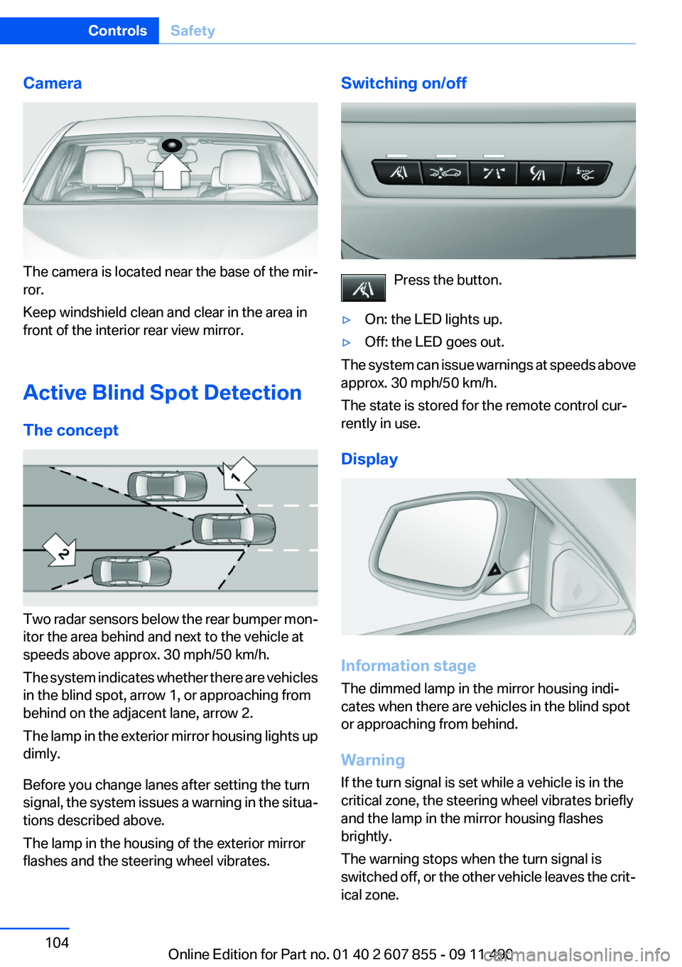
Two radar sensors below the rear bumper mon‐
itor the area behind and next to the vehicle at
speeds above approx. 30 mph/50 km/h.
The system indicates whether there are vehicles
in the blind spot, arrow 1, or approaching from
behind on the adjacent lane, arrow 2.
The lamp in the exterior mirror housing lights up
dimly.
Before you change lanes after setting the turn
signal, the system issues a warning in the situa‐
tions described above.
The lamp in the housing of the exterior mirror
flashes and the steering wheel vibrates.
Switching on/off
Press the button.
▷On: the LED lights up.▷Off: the LED goes out.
The system can issue warnings at speeds above
approx. 30 mph/50 km/h.
The state is stored for the remote control cur‐
rently in use.
Display
Information stage
The dimmed lamp in the mirror housing indi‐
cates when there are vehicles in the blind spot
or approaching from behind.
Warning
If the turn signal is set while a vehicle is in the
critical zone, the steering wheel vibrates briefly
and the lamp in the mirror housing flashes
brightly.
The warning stops when the turn signal is
switched off, or the other vehicle leaves the crit‐
ical zone.
Seite 104ControlsSafety104
Online Edition for Part no. 01 40 2 607 855 - 09 11 490
Page 126 of 321
▷When using a pressure washer, keep the
sprayer moving and maintain a distance of
at least 12 in/30 cm from the sensors.
Surround View
The concept
Surround View includes the following systems:
▷Backup camera, refer to page 127.▷Side View, refer to page 130.▷Top View, refer to page 126.
It assists the driver when parking, maneuvering
and on blind driveways and intersections.
Top View
The concept
Top View assists you in parking and maneuver‐
ing. The area around the doors and the road area
around the vehicle are shown on the Control
Display for this purpose.
Capturing the image
The image is captured by two cameras
integrated in the exterior mirrors and by the
backup camera.
The range equals:
▷approx. 10 ft/3 m to the side.▷approx. 7 ft/2 m to the rear.
In this way, obstacles up to the height of the ex‐
terior mirrors are detected early.
System limits
Top View cannot be used in the following situa‐
tions:
▷With a door open.▷With the tailgate open.▷With an exterior mirror folded in.▷In poor light.A Check Control message is displayed in some
of these situations.
Check the traffic situation as well
Check the traffic situation around the ve‐
hicle with your own eyes. Otherwise, an accident
could result from road users or objects located
outside the picture area of the cameras.◀
Switching on automatically
Select transmission position R with the engine
running.
The Top View and PDC images are displayed if
the system is switched on via iDrive.
Automatic deactivation during forward
travel
The system switches off when a certain driving
distance or speed is exceeded.
Switch the system back on if necessary.
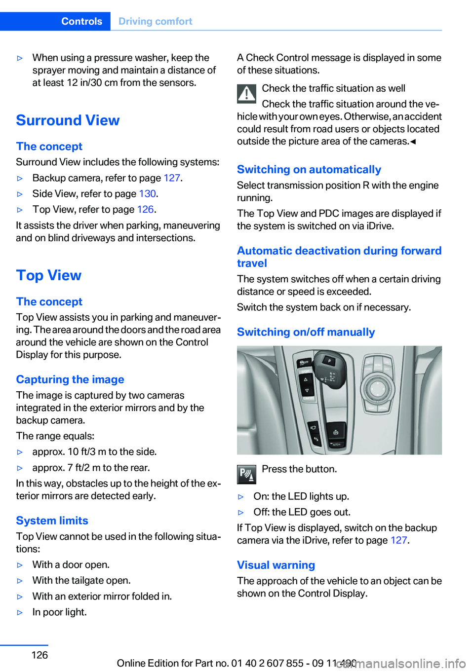
Switching on/off manually
Press the button.
▷On: the LED lights up.▷Off: the LED goes out.
If Top View is displayed, switch on the backup
camera via the iDrive, refer to page 127.
Visual warning
The approach of the vehicle to an object can be
shown on the Control Display.
Seite 126ControlsDriving comfort126
Online Edition for Part no. 01 40 2 607 855 - 09 11 490
Page 127 of 321
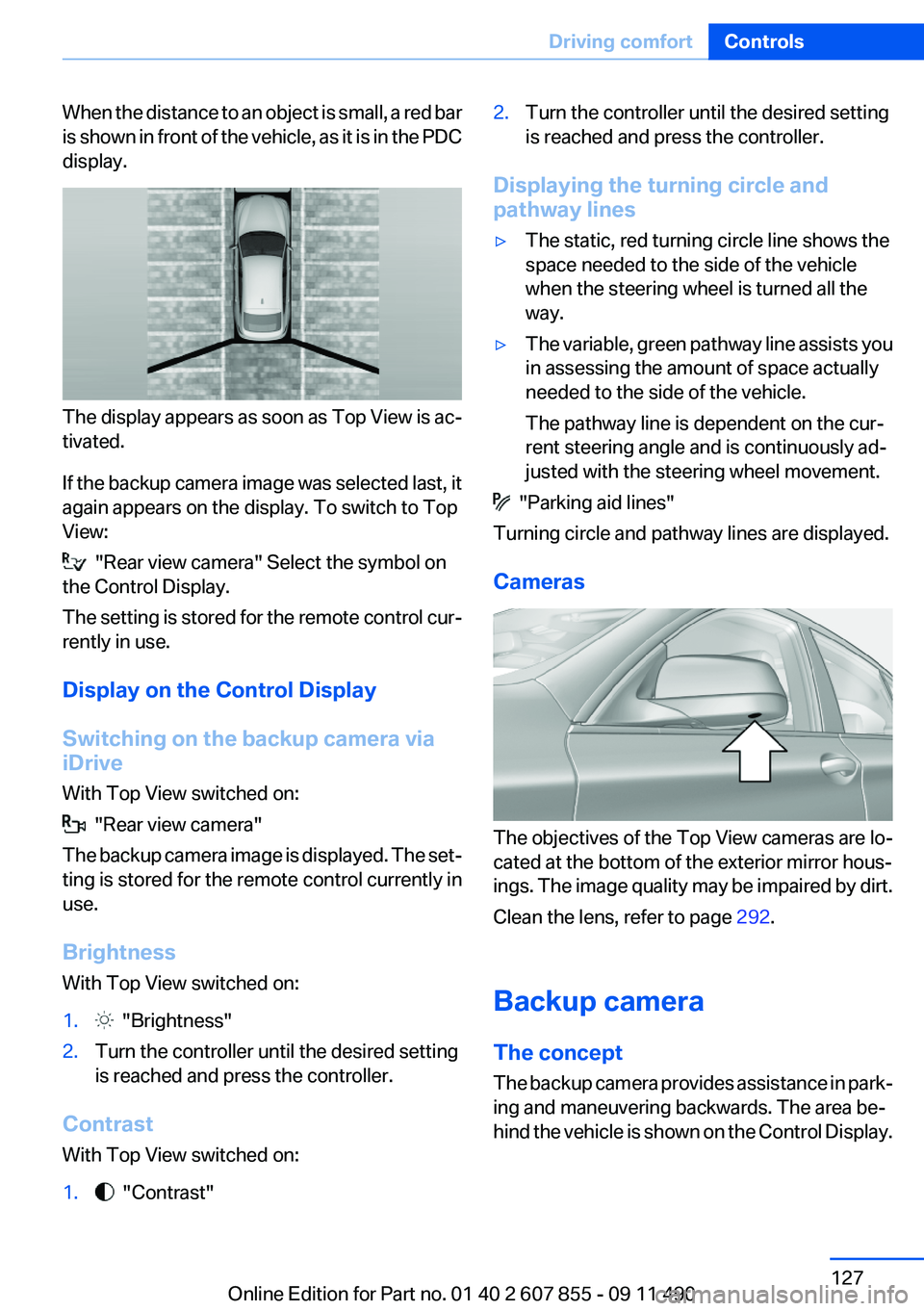
When the distance to an object is small, a red bar
is shown in front of the vehicle, as it is in the PDC
display.
The display appears as soon as Top View is ac‐
tivated.
If the backup camera image was selected last, it
again appears on the display. To switch to Top
View:
"Rear view camera" Select the symbol on
the Control Display.
The setting is stored for the remote control cur‐
rently in use.
Display on the Control Display
Switching on the backup camera via
iDrive
With Top View switched on:
"Rear view camera"
The backup camera image is displayed. The set‐
ting is stored for the remote control currently in
use.
Brightness
With Top View switched on:
1. "Brightness"2.Turn the controller until the desired setting
is reached and press the controller.
Contrast
With Top View switched on:
1. "Contrast"2.Turn the controller until the desired setting
is reached and press the controller.
Displaying the turning circle and
pathway lines
▷The static, red turning circle line shows the
space needed to the side of the vehicle
when the steering wheel is turned all the
way.▷The variable, green pathway line assists you
in assessing the amount of space actually
needed to the side of the vehicle.
The pathway line is dependent on the cur‐
rent steering angle and is continuously ad‐
justed with the steering wheel movement.
"Parking aid lines"
Turning circle and pathway lines are displayed.
Cameras
The objectives of the Top View cameras are lo‐
cated at the bottom of the exterior mirror hous‐
ings. The image quality may be impaired by dirt.
Clean the lens, refer to page 292.
Backup camera
The concept
The backup camera provides assistance in park‐
ing and maneuvering backwards. The area be‐
hind the vehicle is shown on the Control Display.
Seite 127Driving comfortControls127
Online Edition for Part no. 01 40 2 607 855 - 09 11 490
Page 312 of 321
Concierge service 250
Condensation on win‐ dows 137
Condensation under the vehi‐ cle 160
Condition Based Service CBS 276
Confirmation signal 35
Contacts 239, 247
Control Display 16
Control Display, settings 87
Controller 16
Control systems, driving sta‐ bility 106
Convenient opening 34
Coolant 274
Coolant temperature 82
Cooling function 138
Cooling, maximum 138
Cooling system 274
Corrosion on brake discs 160
Cruise control 121
Cruise control, active with Stop & Go 114
Cruising range 82
Cupholder 152
Curb weight 298
Current fuel consumption 83
Current location, storing 170
Customer Relations 252
D
Damage, tires 266
Damping control, dy‐ namic 109
Data, technical 296
Date 82
Daytime running lights 90
Defrosting, refer to Windows, defrosting 137
Destination distance 85
Destination guidance 176
Destination guidance with in‐ termediate destinations 174 Destination input, naviga‐
tion 168
Digital clock 82
Digital radio 189
Dimensions 296
Dimmable exterior mirrors 61
Dimmable interior rearview mirror 61
Direction indicator, refer to Turn signals 72
Display in front wind‐ shield 134
Display lighting, refer to Instru‐ ment lighting 92
Displays 78
Displays, cleaning 292
Disposal, coolant 275
Disposal, vehicle battery 282
Distance control, refer to PDC 123
Distance, selecting for ACC 116
Distance to destination 85
Divided screen view, split screen 20
Door lock, refer to Remote control 30
Doors, Automatic Soft Clos‐ ing 38
Downhill control 108
Drive-off assistant 106
Drive-off assistant, refer to DSC 106
Driving Experience Switch 110
Driving instructions, breaking in 158
Driving notes, general 158
Driving stability control sys‐ tems 106
Driving tips 158
DSC Dynamic Stability Con‐ trol 106
DTC driving dynamics 107
DTC Dynamic Traction Con‐ trol 107 DVD/CD 196
DVD/CD notes 202
DVD/CD player, rear 217
DVD changer 200
DVD settings 199
DVDs, storing 203
DVD, video 198
Dynamic Damping Con‐ trol 109
Dynamic destination guid‐ ance 182
Dynamic Drive 109
Dynamic Stability Control DSC 106
Dynamic Traction Control DTC 107
E
Electronic displays, instru‐ ment cluster 79
Electronic Stability Program ESP, refer to DSC 106
Emergency detection, remote control 31
Emergency release, door lock 37
Emergency release, fuel filler flap 258
Emergency release, parking brake 69
Emergency Request 284
Emergency service, refer to Roadside Assistance 285
Emergency start function, en‐ gine start 31
Emergency unlocking, tail‐ gate 41
Energy Control 83
Energy recovery 83
Engine compartment 271
Engine compartment, working in 271
Engine coolant 274
Engine oil 273
Engine oil, adding 273 Seite 312ReferenceEverything from A to Z312
Online Edition for Part no. 01 40 2 607 855 - 09 11 490