navigation system BMW 535I GRAN TURISMO 2013 Owners Manual
[x] Cancel search | Manufacturer: BMW, Model Year: 2013, Model line: 535I GRAN TURISMO, Model: BMW 535I GRAN TURISMO 2013Pages: 240, PDF Size: 5.49 MB
Page 6 of 240
NotesUsing this Owner's Manual
The fastest way to find information on a partic‐
ular topic is by using the index.
An initial overview of the vehicle is provided in
the first chapter.
Updates made after the editorial
deadline
Any updates made after the editorial deadline for
the Owner's Manuals are located in the appen‐
dix of the printed quick reference for the vehicle.
User's manual for Navigation,
Entertainment, Communication
The topics of Navigation, Entertainment, Com‐
munication and the short commands of the
voice activation system are described in a sep‐
arate user's manual, which is also included with
the onboard literature.
Additional sources of information
Should you have any questions, your service
center will be glad to advise you at any time.
Information on BMW, e.g., on technology, is
available on the Internet: bmwusa.com.
Symbols
Indicates precautions that must be followed
precisely in order to avoid the possibility of per‐
sonal injury and serious damage to the vehicle.
◄ Marks the end of a specific item of informa‐
tion.
"..." Identifies Control Display texts used to se‐
lect individual functions.
›...‹ Verbal instructions to use with the voice ac‐
tivation system.
››...‹‹ Identifies the answers generated by the
voice activation system.
Refers to measures that can be taken to help
protect the environment.
Symbols on vehicle components
Indicates that you should consult the rele‐
vant section of this Owner's Manual for infor‐
mation on a particular part or assembly.
Vehicle equipment
This Owner's Manual describes all models and
all standard, country-specific and optional
equipment that is offered in the model series.
Therefore, in this Owner's Manual, equipment is
also described and illustrated that is not availa‐
ble in your vehicle, e.g. because of the selected
optional equipment or the country-specific var‐
iants.
This also applies for safety-related functions
and systems.
For options and equipment not described in this
Owner's Manual, please refer to the Supple‐
mentary Owner's Manuals.
On right-hand drive vehicles, some controls are
arranged differently than shown in the illustra‐
tions.
Status of the Owner's Manual
The manufacturer of your vehicle pursues a pol‐
icy of constant development that is conceived
to ensure that our vehicles continue to embody
the highest quality and safety standards. In rare
cases, therefore, the features described in this
Owner's Manual may differ from those in your
vehicle.
Seite 6Notes6
Online Edition for Part no. 01 40 2 917 498 - II/13
Page 14 of 240
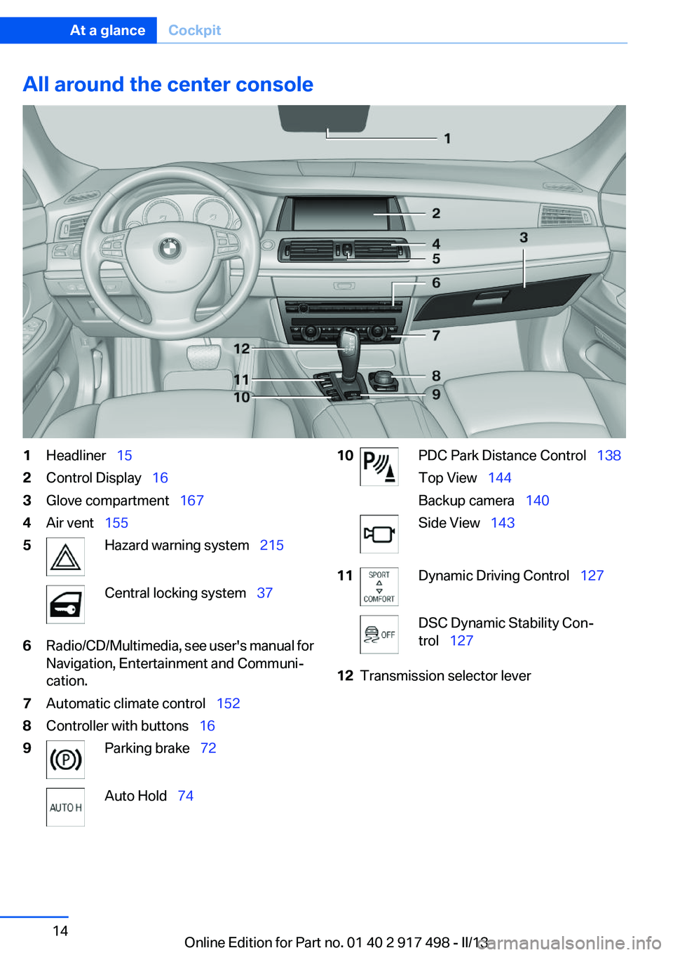
All around the center console1Headliner 152Control Display 163Glove compartment 1674Air vent 1555Hazard warning system 215Central locking system 376Radio/CD/Multimedia, see user's manual for
Navigation, Entertainment and Communi‐
cation.7Automatic climate control 1528Controller with buttons 169Parking brake 72Auto Hold 7410PDC Park Distance Control 138
Top View 144
Backup camera 140Side View 14311Dynamic Driving Control 127DSC Dynamic Stability Con‐
trol 12712Transmission selector leverSeite 14At a glanceCockpit14
Online Edition for Part no. 01 40 2 917 498 - II/13
Page 21 of 240
Running a functionPress the button.
The function will run immediately. This
means, for example, that the number is dialed
when a phone number is selected.
Displaying the button assignment
Use a finger to touch the buttons. Do not wear
gloves or use objects.
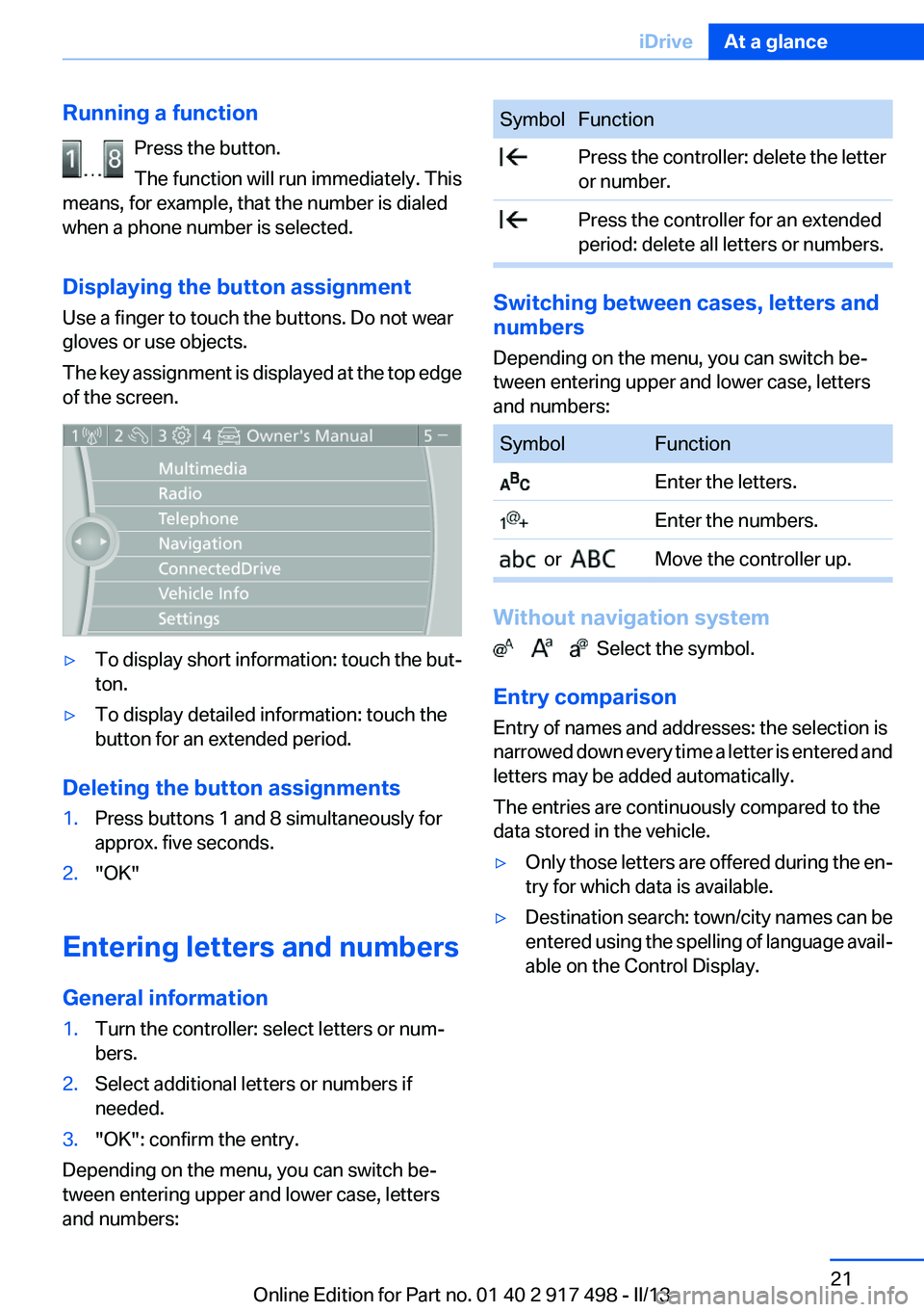
The key assignment is displayed at the top edge
of the screen.▷To display short information: touch the but‐
ton.▷To display detailed information: touch the
button for an extended period.
Deleting the button assignments
1.Press buttons 1 and 8 simultaneously for
approx. five seconds.2."OK"
Entering letters and numbers
General information
1.Turn the controller: select letters or num‐
bers.2.Select additional letters or numbers if
needed.3."OK": confirm the entry.
Depending on the menu, you can switch be‐
tween entering upper and lower case, letters
and numbers:
SymbolFunction Press the controller: delete the letter
or number. Press the controller for an extended
period: delete all letters or numbers.
Switching between cases, letters and
numbers
Depending on the menu, you can switch be‐
tween entering upper and lower case, letters
and numbers:
SymbolFunction Enter the letters. Enter the numbers. or Move the controller up.
Without navigation system
Select the symbol.
Entry comparison
Entry of names and addresses: the selection is
narrowed down every time a letter is entered and
letters may be added automatically.
The entries are continuously compared to the
data stored in the vehicle.
▷Only those letters are offered during the en‐
try for which data is available.▷Destination search: town/city names can be
entered using the spelling of language avail‐
able on the Control Display.Seite 21iDriveAt a glance21
Online Edition for Part no. 01 40 2 917 498 - II/13
Page 23 of 240
List of short commands of the voice activation
system, see Navigation, Entertainment, Com‐
munication Owner's Manual.
Help dialog for the voice activation
system
Calling up help dialog: ›Help‹
Additional commands for the help dialog:▷›Help with examples‹: information about the
current operating options and the most im‐
portant commands for them are announced.▷›Help with voice activation‹: information
about the principle of operation for the voice
activation system is announced.
Example: playing back a CD
Via the main menu
The commands of the menu items are spoken
just as they are selected via the controller.
1.Switch on the Entertainment sound output
if necessary.2. Press the button on the steering
wheel.3.›Multimedia‹
The medium last played is played back.4.›C D‹5.›C D drive‹6.›Track ...‹, e.g., CD track 4.
Via short command
Playback of the CD can also be started via a short
command.
1.Switch on the Entertainment sound output
if necessary.2. Press the button on the steering
wheel.3.›C D drive track ...‹, e.g., CD track 4.Setting the voice dialog
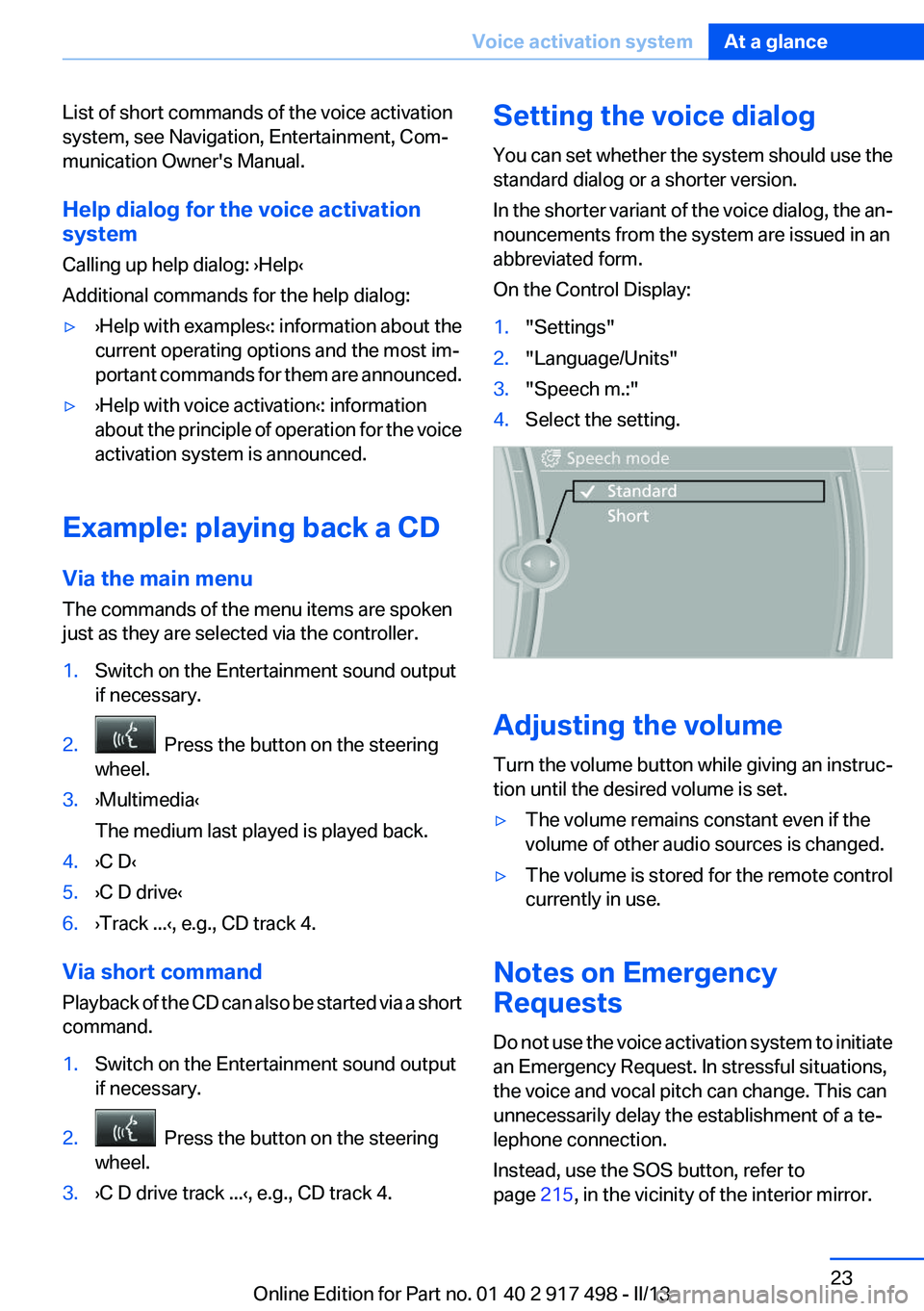
You can set whether the system should use the
standard dialog or a shorter version.
In the shorter variant of the voice dialog, the an‐
nouncements from the system are issued in an
abbreviated form.
On the Control Display:1."Settings"2."Language/Units"3."Speech m.:"4.Select the setting.
Adjusting the volume
Turn the volume button while giving an instruc‐
tion until the desired volume is set.
▷The volume remains constant even if the
volume of other audio sources is changed.▷The volume is stored for the remote control
currently in use.
Notes on Emergency
Requests
Do not use the voice activation system to initiate
an Emergency Request. In stressful situations,
the voice and vocal pitch can change. This can
unnecessarily delay the establishment of a te‐
lephone connection.
Instead, use the SOS button, refer to
page 215, in the vicinity of the interior mirror.
Seite 23Voice activation systemAt a glance23
Online Edition for Part no. 01 40 2 917 498 - II/13
Page 83 of 240
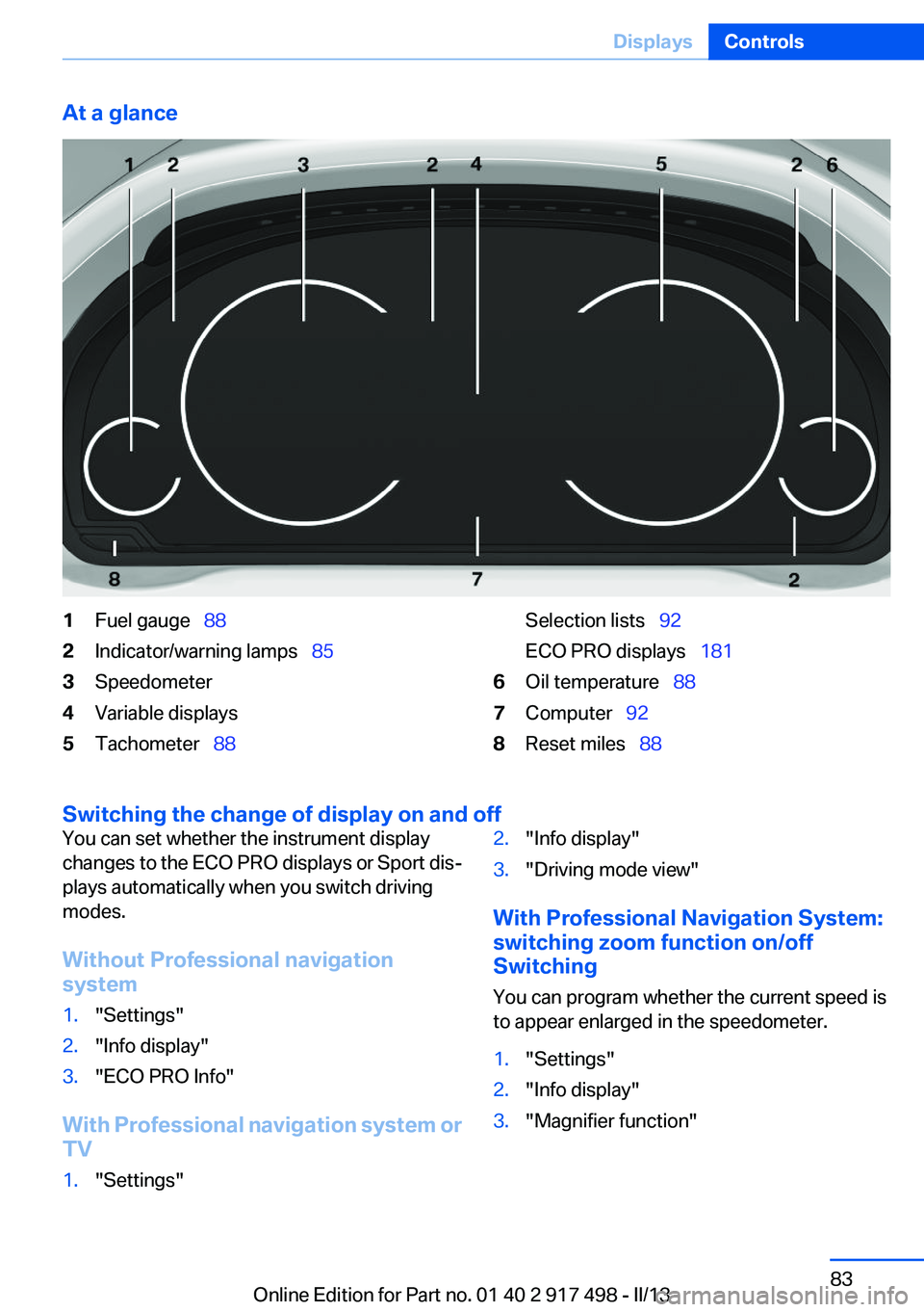
At a glance1Fuel gauge 882Indicator/warning lamps 853Speedometer4Variable displays5Tachometer 88Selection lists 92
ECO PRO displays 1816Oil temperature 887Computer 928Reset miles 88
Switching the change of display on and off
You can set whether the instrument display
changes to the ECO PRO displays or Sport dis‐
plays automatically when you switch driving
modes.
Without Professional navigation
system1."Settings"2."Info display"3."ECO PRO Info"
With Professional navigation system or
TV
1."Settings"2."Info display"3."Driving mode view"
With Professional Navigation System:
switching zoom function on/off
Switching
You can program whether the current speed is
to appear enlarged in the speedometer.
1."Settings"2."Info display"3."Magnifier function"Seite 83DisplaysControls83
Online Edition for Part no. 01 40 2 917 498 - II/13
Page 89 of 240
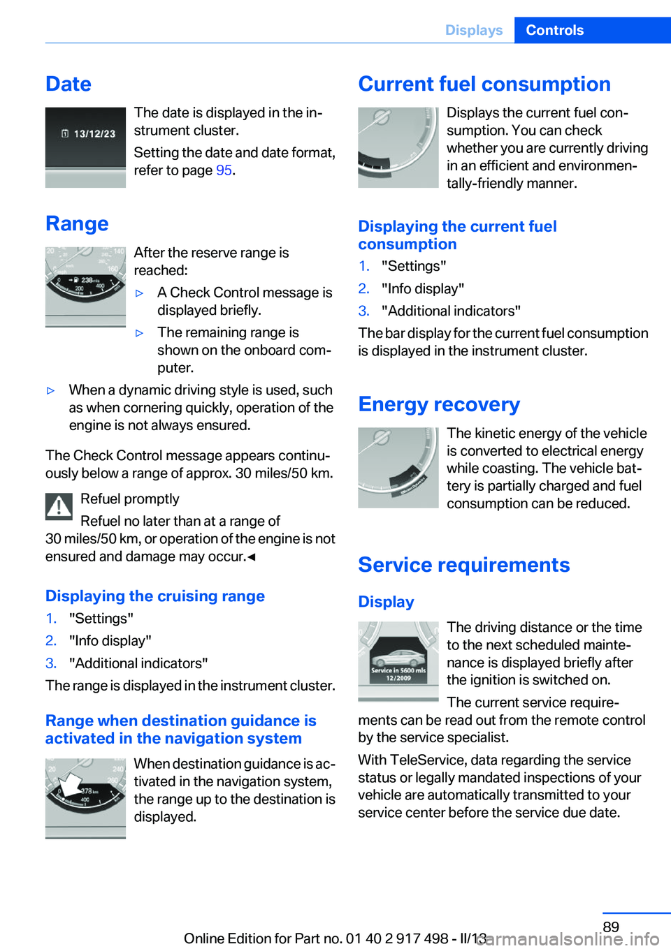
DateThe date is displayed in the in‐
strument cluster.
Setting the date and date format,
refer to page 95.
Range After the reserve range is
reached:▷A Check Control message is
displayed briefly.▷The remaining range is
shown on the onboard com‐
puter.▷When a dynamic driving style is used, such
as when cornering quickly, operation of the
engine is not always ensured.
The Check Control message appears continu‐
ously below a range of approx. 30 miles/50 km.
Refuel promptly
Refuel no later than at a range of
30 miles/50 km, or operation of the engine is not
ensured and damage may occur.◀
Displaying the cruising range
1."Settings"2."Info display"3."Additional indicators"
The range is displayed in the instrument cluster.
Range when destination guidance is
activated in the navigation system
When destination guidance is ac‐
tivated in the navigation system,
the range up to the destination is
displayed.
Current fuel consumption
Displays the current fuel con‐
sumption. You can check
whether you are currently driving
in an efficient and environmen‐
tally-friendly manner.
Displaying the current fuel
consumption1."Settings"2."Info display"3."Additional indicators"
The bar display for the current fuel consumption
is displayed in the instrument cluster.
Energy recovery The kinetic energy of the vehicle
is converted to electrical energy
while coasting. The vehicle bat‐
tery is partially charged and fuel
consumption can be reduced.
Service requirements
Display The driving distance or the time
to the next scheduled mainte‐
nance is displayed briefly after
the ignition is switched on.
The current service require‐
ments can be read out from the remote control
by the service specialist.
With TeleService, data regarding the service
status or legally mandated inspections of your
vehicle are automatically transmitted to your
service center before the service due date.
Seite 89DisplaysControls89
Online Edition for Part no. 01 40 2 917 498 - II/13
Page 90 of 240
Detailed information on service
requirements
More information on the scope of service re‐
quired can be displayed on the Control Display.1."Vehicle Info"2."Vehicle status"3. "Service required"
Required maintenance procedures and le‐
gally mandated inspections are displayed.4.Select an entry to call up detailed informa‐
tion.
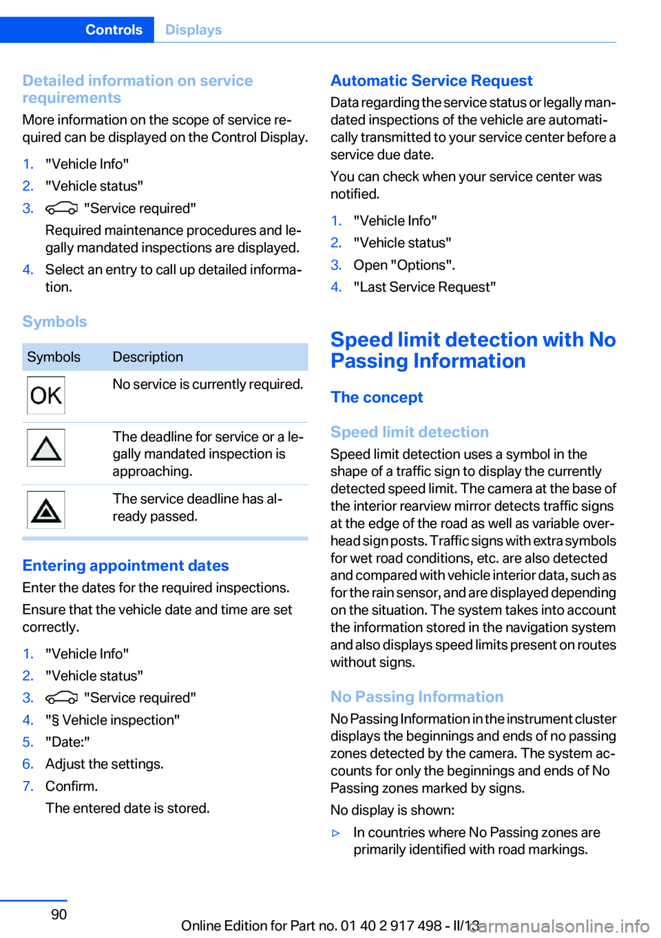
Symbols
SymbolsDescriptionNo service is currently required.The deadline for service or a le‐
gally mandated inspection is
approaching.The service deadline has al‐
ready passed.
Entering appointment dates
Enter the dates for the required inspections.
Ensure that the vehicle date and time are set
correctly.
1."Vehicle Info"2."Vehicle status"3. "Service required"4."§ Vehicle inspection"5."Date:"6.Adjust the settings.7.Confirm.
The entered date is stored.Automatic Service Request
Data regarding the service status or legally man‐
dated inspections of the vehicle are automati‐
cally transmitted to your service center before a
service due date.
You can check when your service center was
notified.1."Vehicle Info"2."Vehicle status"3.Open "Options".4."Last Service Request"
Speed limit detection with No
Passing Information
The concept
Speed limit detection
Speed limit detection uses a symbol in the
shape of a traffic sign to display the currently
detected speed limit. The camera at the base of
the interior rearview mirror detects traffic signs
at the edge of the road as well as variable over‐
head sign posts. Traffic signs with extra symbols
for wet road conditions, etc. are also detected
and compared with vehicle interior data, such as
for the rain sensor, and are displayed depending
on the situation. The system takes into account
the information stored in the navigation system
and also displays speed limits present on routes
without signs.
No Passing Information
No Passing Information in the instrument cluster
displays the beginnings and ends of no passing
zones detected by the camera. The system ac‐
counts for only the beginnings and ends of No
Passing zones marked by signs.
No display is shown:
▷In countries where No Passing zones are
primarily identified with road markings.Seite 90ControlsDisplays90
Online Edition for Part no. 01 40 2 917 498 - II/13
Page 92 of 240
▷If the speed limits stored in the navigation
system are incorrect.▷In areas not covered by the navigation sys‐
tem.▷When roads differ from the navigation, such
as due to changes in the road network.▷When passing buses or trucks with a speed
sticker.▷If the traffic signs are non-conforming.▷During calibration of the camera immedi‐
ately after vehicle shipment.
Selection lists in the
instrument cluster
The concept
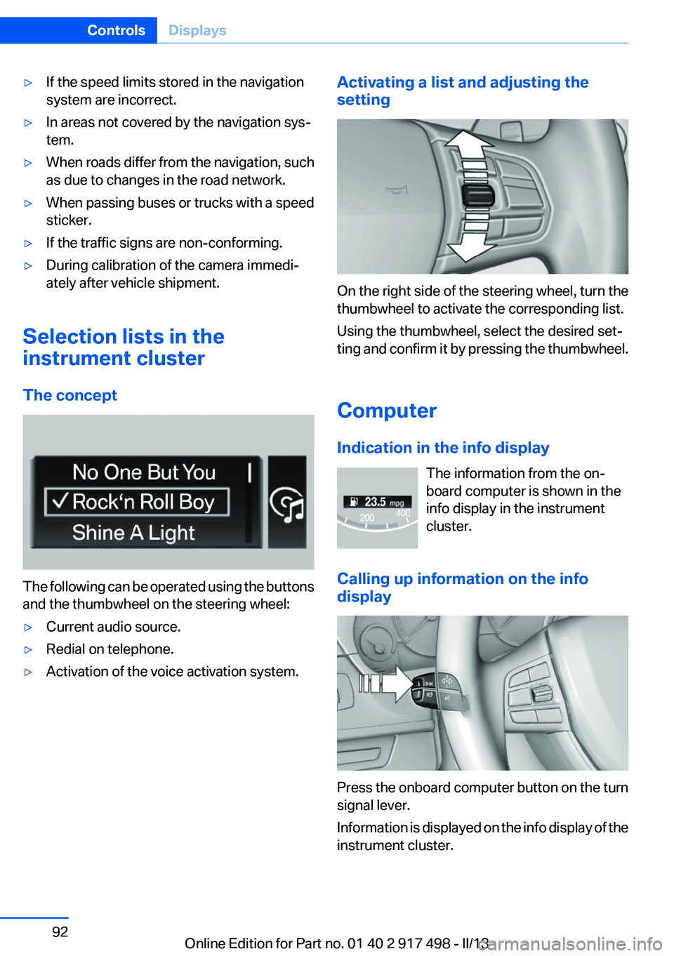
The following can be operated using the buttons
and the thumbwheel on the steering wheel:
▷Current audio source.▷Redial on telephone.▷Activation of the voice activation system.Activating a list and adjusting the
setting
On the right side of the steering wheel, turn the
thumbwheel to activate the corresponding list.
Using the thumbwheel, select the desired set‐
ting and confirm it by pressing the thumbwheel.
Computer
Indication in the info display The information from the on‐
board computer is shown in the
info display in the instrument
cluster.
Calling up information on the info
display
Press the onboard computer button on the turn
signal lever.
Information is displayed on the info display of the
instrument cluster.
Seite 92ControlsDisplays92
Online Edition for Part no. 01 40 2 917 498 - II/13
Page 93 of 240
Information at a glance
Repeatedly pressing the button on the turn sig‐
nal lever calls up the following information on the
info display:▷Range.▷Average fuel consumption.▷Average speed.▷Date.▷Speed limit detection.▷Time of arrival.
When destination guidance is activated in
the navigation system.▷Distance to destination.
When destination guidance is activated in
the navigation system.▷Arrow view of navigation system.
When destination guidance is activated in
the navigation system.
When the arrow view in the Head-up Display
is inactive.▷ECO PRO bonus range.
Adjusting the info display
You can select what information from the on‐
board computer is to be displayed on the info
display of the instrument cluster.
1."Settings"2."Info display"3.Select the desired displays.
Information in detail
Range
Displays the estimated cruising range available
with the remaining fuel.
It is calculated based on your driving style over
the last 20 miles/30 km. If there is only enough
fuel left for less than 45 miles/80 km, the color
of the display changes.
Average fuel consumption
This is calculated for the period during which the
engine is running.
The average fuel consumption is calculated for
the distance traveled since the last reset by the
onboard computer.
Average speed
Periods in which the vehicle is parked with the
engine manually stopped do not enter into the
calculation of the average speed.
Resetting average values
Press and hold the computer button on the turn
signal lever.
Distance to destination
The distance remaining to the destination is dis‐
played if a destination is entered in the naviga‐
tion system before the trip is started.
The distance to the destination is adopted au‐
tomatically.
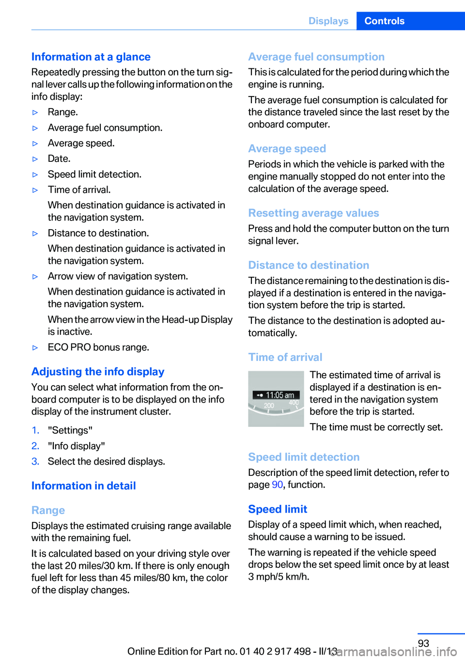
Time of arrival The estimated time of arrival is
displayed if a destination is en‐
tered in the navigation system
before the trip is started.
The time must be correctly set.
Speed limit detection
Description of the speed limit detection, refer to
page 90, function.
Speed limit
Display of a speed limit which, when reached,
should cause a warning to be issued.
The warning is repeated if the vehicle speed
drops below the set speed limit once by at least
3 mph/5 km/h.Seite 93DisplaysControls93
Online Edition for Part no. 01 40 2 917 498 - II/13
Page 103 of 240
Protective action
Airbags are not triggered in every impact situa‐
tion, e.g., in less severe accidents or rear-end
collisions.
Information on how to ensure the optimal
protective effect of the airbags▷Keep at a distance from the airbags.▷Always grasp the steering wheel on the
steering wheel rim, holding your hands at
the 3 o'clock and 9 o'clock positions, to keep
the danger of injury to your hands or arms as
low as possible if the airbag is triggered.▷There should be no people, animals, or ob‐
jects between an airbag and a person.▷Do not use the cover of the front airbag on
the front passenger side as a storage area.▷Keep the dashboard and window on the
front passenger side clear, i.e., do not cover
with adhesive labels or coverings, and do not
attach holders such as for navigation instru‐
ments and mobile phones.▷Make sure that the front passenger is sitting
correctly, i.e., keeps his or her feet and legs
in the footwell; otherwise, leg injuries can
occur if the front airbag is triggered.▷Do not place slip covers, seat cushions or
other objects on the front passenger seat
that are not approved specifically for seats
with integrated side airbags.▷Do not hang pieces of clothing, such as jack‐
ets, over the backrests.▷Make sure that occupants keep their heads
away from the side airbag and do not rest
against the head airbag; otherwise, injuries
can occur if the airbags are triggered.▷Do not remove the airbag restraint system.▷Do not remove the steering wheel.▷Do not apply adhesive materials to the air‐
bag cover panels, cover them or modify
them in any way.▷Never modify either the individual compo‐
nents or the wiring in the airbag system. This
also applies to steering wheel covers, the
dashboard, the seats, the roof pillars and the
sides of the headliner.◀
Even when all instructions are followed closely,
injury from contact with the airbags cannot be
ruled out in certain situations.
The ignition and inflation noise may lead to
short-term and, in most cases, temporary hear‐
ing impairment in sensitive individuals.
In the case of a malfunction, deactivation
and after triggering of the airbags
Do not touch the individual components imme‐
diately after the system has been triggered; oth‐
erwise, there is the danger of burns.
Only have the airbags checked, repaired or dis‐
mantled and the airbag generator scrapped by
your service center or a workshop that has the
necessary authorization for handling explosives.
Non-professional attempts to service the sys‐
tem could lead to failure in an emergency or un‐
desired triggering of the airbag, either of which
could result in injury.◀
Warnings and information on the airbags are
also found on the sun visors.
Functional readiness of the airbag
system
When the ignition is switch on, the warn‐
ing lamp in the instrument cluster lights
up briefly and thereby indicates the op‐
erational readiness of the entire airbag system
and the belt tensioner.
Airbag system malfunctioning
▷Warning lamp does not come on when the
ignition is turned on.▷The warning lamp lights up continuously.Seite 103SafetyControls103
Online Edition for Part no. 01 40 2 917 498 - II/13