weight BMW 535I XDRIVE GRAN TURISMO 2013 Owners Manual
[x] Cancel search | Manufacturer: BMW, Model Year: 2013, Model line: 535I XDRIVE GRAN TURISMO, Model: BMW 535I XDRIVE GRAN TURISMO 2013Pages: 240, PDF Size: 5.49 MB
Page 49 of 240
AdjustingVehicle equipment
All standard, country-specific and optional
equipment that is offered in the model series is
described in this chapter. Therefore, equipment
is also described that is not available in a vehicle,
e. g., because of the selected optional equip‐
ment or country variant. This also applies for
safety-related functions and systems.
Sitting safely
The ideal seating position can make a vital con‐
tribution to relaxed, fatigue-free driving.
The seating position plays an important role in
an accident in combination with:▷Safety belts, refer to page 56.▷Head restraints, refer to page 57.▷Airbags, refer to page 102.
Front seats
General information Do not adjust the seat while driving
Do not adjust the driver's seat while driv‐
ing, or the seat could respond with unexpected
movement and the ensuing loss of vehicle con‐
trol could lead to an accident.◀
Do not incline the backrest too far to the
rear
Also on the front passenger side, do not incline
the backrest on the front passenger side too far
to the rear during driving, or there is a risk of
slipping under the safety belt in the event of an
accident. This would eliminate the protection
normally provided by the belt.◀
Semi-electrically adjustable seats
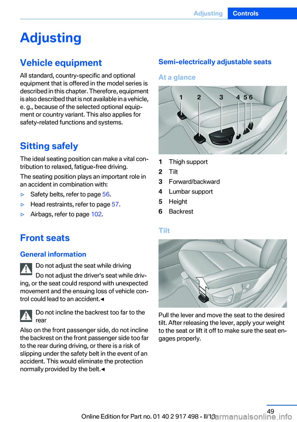
At a glance1Thigh support2Tilt3Forward/backward4Lumbar support5Height6Backrest
Tilt
Pull the lever and move the seat to the desired
tilt. After releasing the lever, apply your weight
to the seat or lift it off to make sure the seat en‐
gages properly.
Seite 49AdjustingControls49
Online Edition for Part no. 01 40 2 917 498 - II/13
Page 53 of 240
The highest level is active when three LEDs are
lit.
If when the seat ventilation is turned on the Max‐
imum Cooling function is activated, the seat
ventilation automatically switches to the highest
level. When the Maximum Cooling function is
switched off, the unit switches back to the pre‐
viously set level.
After a short time, the system automatically
moves down one level in order to prevent ex‐
cessive cooling.
Switching off Press the button longer.
The LEDs go out.
Rear seats
General information
The switches for adjusting the seats are located
on the center armrest of the rear seats.
Center armrest
When folding down the center armrest,
ensure that the area below the center head re‐
straint is clear. Otherwise, injury may result.◀
Manually adjustable seats
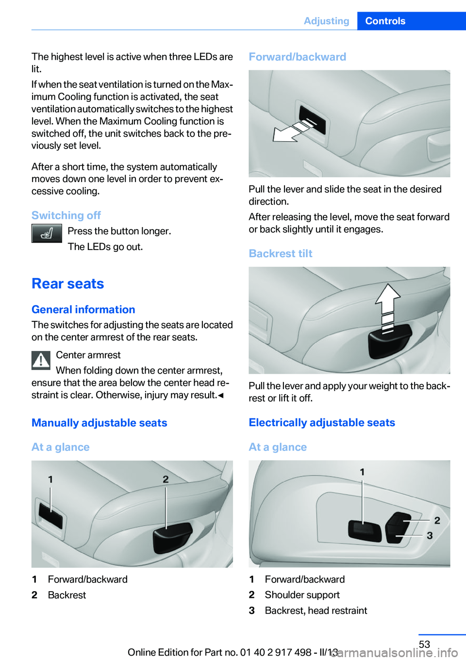
At a glance1Forward/backward2BackrestForward/backward
Pull the lever and slide the seat in the desired
direction.
After releasing the level, move the seat forward
or back slightly until it engages.
Backrest tilt
Pull the lever and apply your weight to the back‐
rest or lift it off.
Electrically adjustable seats
At a glance
1Forward/backward2Shoulder support3Backrest, head restraintSeite 53AdjustingControls53
Online Edition for Part no. 01 40 2 917 498 - II/13
Page 63 of 240
Transporting children safelyVehicle equipment
All standard, country-specific and optional
equipment that is offered in the model series is
described in this chapter. Therefore, equipment
is also described that is not available in a vehicle,
e. g., because of the selected optional equip‐
ment or country variant. This also applies for
safety-related functions and systems.
The right place for children
Note Children in the vehicle
Do not leave children unattended in the
vehicle; otherwise, they could endanger them‐
selves and other persons, e.g., by opening the
doors.◀
Children should always be in the rear
Accident research shows that the safest place
for children is in the back seat.
Transporting children in the rear
Only transport children younger than
13 years of age or shorter than 5 ft/150 cm in the
rear in child restraint fixing systems provided in
accordance with the age, weight and size of the
child; otherwise, there is an increased risk of in‐
jury in an accident.
Children 13 years of age or older must wear a
safety belt as soon as a suitable child restraint
fixing system can no longer be used, due to their
age, weight and size.◀
Children on the front passenger seat
Should it ever be necessary to use a child re‐
straint fixing system in the front passenger seat,
make sure that the front, knee and side airbags
on the front passenger side are deactivated. Au‐tomatic deactivation of front passenger airbags,
refer to page 104.
Note Deactivated front passenger airbags
If a child restraint fixing system is used in
the front passenger seat, the front passenger
airbags must be deactivated; otherwise, there is
an increased risk of injury to the child when the
airbags are triggered, even with a child restraint
fixing system.◀
Installing child restraint fixing
systems
Before mounting
If the rear seat backrests are adjustable or can
be folded down:
Lock the rear seat backrests in position
Before mounting child restraint fixing sys‐
tems, place the seat backrest as far as possible
at an angle at which the child seat is resting
firmly against the backrest and all backrests can
be locked securely in place. Otherwise, the child
seat will not be as stable as it should be, and
there is increased danger of injury due to unex‐
pected movement of the seat backrest.◀
Notes Manufacturer's information for child re‐
straint fixing systems
To select, mount and use child restraint fixing
systems, observe the information provided by
the system manufacturer; otherwise, the pro‐
tective effect can be impaired.◀Seite 63Transporting children safelyControls63
Online Edition for Part no. 01 40 2 917 498 - II/13
Page 65 of 240
Mounts for the lower LATCH anchors
The lower anchors may be used to attach the
CRS to the vehicle seat up to a combined child
and CRS weight of 65 lb when the child is restr-
ained by the internal harnesses.
Correctly engage the lower LATCH an‐
chors
Make sure that the lower LATCH anchors have
properly engaged and that the child restraint fix‐
ing system is resting snugly against the back‐
rest; otherwise, the degree of protection offered
may be reduced.◀
Before mounting the LATCH child restraint fix‐
ing system, pull the belt away from the child re‐
straint fixing system.
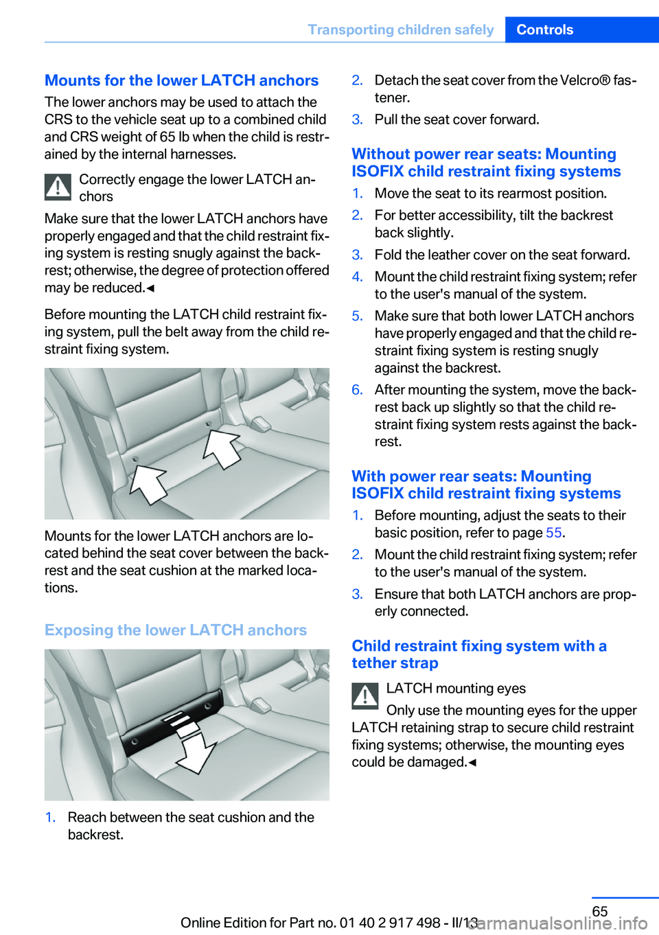
Mounts for the lower LATCH anchors are lo‐
cated behind the seat cover between the back‐
rest and the seat cushion at the marked loca‐
tions.
Exposing the lower LATCH anchors
1.Reach between the seat cushion and the
backrest.2.Detach the seat cover from the Velcro® fas‐
tener.3.Pull the seat cover forward.
Without power rear seats: Mounting
ISOFIX child restraint fixing systems
1.Move the seat to its rearmost position.2.For better accessibility, tilt the backrest
back slightly.3.Fold the leather cover on the seat forward.4.Mount the child restraint fixing system; refer
to the user's manual of the system.5.Make sure that both lower LATCH anchors
have properly engaged and that the child re‐
straint fixing system is resting snugly
against the backrest.6.After mounting the system, move the back‐
rest back up slightly so that the child re‐
straint fixing system rests against the back‐
rest.
With power rear seats: Mounting
ISOFIX child restraint fixing systems
1.Before mounting, adjust the seats to their
basic position, refer to page 55.2.Mount the child restraint fixing system; refer
to the user's manual of the system.3.Ensure that both LATCH anchors are prop‐
erly connected.
Child restraint fixing system with a
tether strap
LATCH mounting eyes
Only use the mounting eyes for the upper
LATCH retaining strap to secure child restraint
fixing systems; otherwise, the mounting eyes
could be damaged.◀
Seite 65Transporting children safelyControls65
Online Edition for Part no. 01 40 2 917 498 - II/13
Page 177 of 240
LoadingVehicle equipment
All standard, country-specific and optional
equipment that is offered in the model series is
described in this chapter. Therefore, equipment
is also described that is not available in a vehicle,
e. g., because of the selected optional equip‐
ment or country variant. This also applies for
safety-related functions and systems.
Hints Overloading the vehicle
To avoid exceeding the approved carrying
capacity of the tires, never overload the vehicle.
Overloading can lead to overheating and in‐
creases the rate at which damage develops in‐
side the tires. This could result in a sudden loss
of tire inflation pressure.◀
No fluids in the trunk
Make sure that fluids do not leak into the
trunk; otherwise, the vehicle may be damaged. ◀
Determining the load limit1.Locate the following statement on your ve‐
hicle’s placard:▷The combined weight of occupants and
cargo should never exceed XXX kg or
YYY lbs. Otherwise, damage to the ve‐hicle and unstable driving situations may
result.2.Determine the combined weight of the
driver and passengers that will be riding in
your vehicle.3.Subtract the combined weight of the driver
and passengers from XXX kilograms or YYY
pounds.4.The resulting figure equals the available
amount of cargo and luggage load capacity.
For example, if the YYY amount equals
1,000 lbs and there will be four 150 lbs pas‐
sengers in your vehicle, the amount of avail‐
able cargo and luggage load capacity is
400 lbs: 1,000 lbs minus 600 lbs = 400 lbs.5.Determine the combined weight of luggage
and cargo being loaded on the vehicle. That
weight may not safely exceed the available
cargo and luggage load capacity calculated
in Step 4.
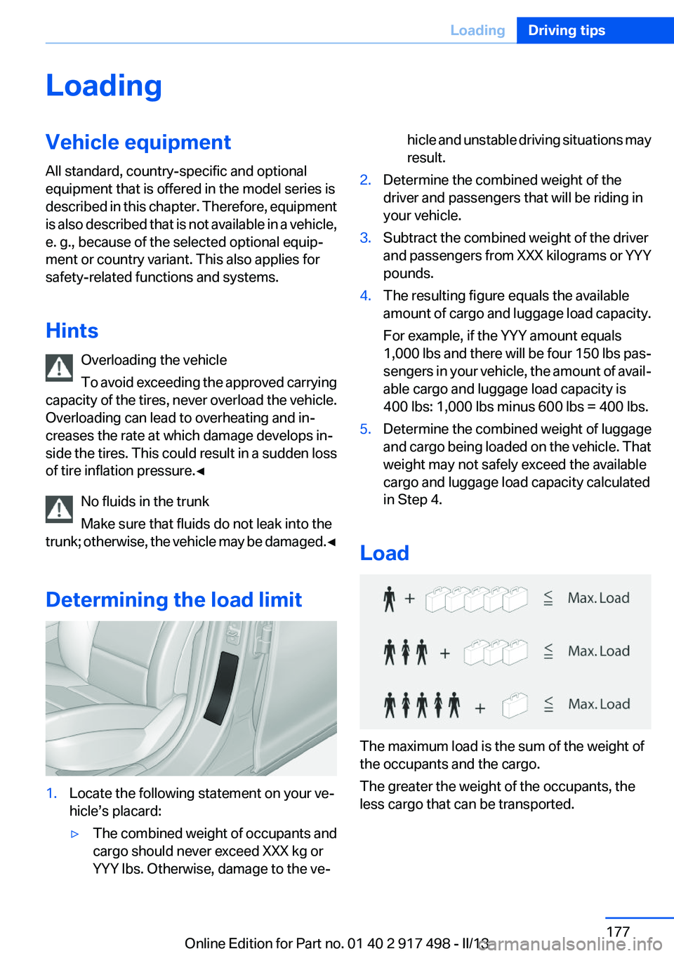
Load
The maximum load is the sum of the weight of
the occupants and the cargo.
The greater the weight of the occupants, the
less cargo that can be transported.
Seite 177LoadingDriving tips177
Online Edition for Part no. 01 40 2 917 498 - II/13
Page 179 of 240
▷Do not exceed the approved roof/axle loads
and the approved gross vehicle weight.▷Distribute the roof load uniformly.▷The roof load should not be too large in area.▷Always place the heaviest pieces on the bot‐
tom.▷Secure the roof luggage firmly, e.g., tie with
ratchet straps.▷Do not let objects project into the opening
path of the tailgate.▷Drive cautiously and avoid sudden acceler‐
ation and braking maneuvers. Take corners
gently.Seite 179LoadingDriving tips179
Online Edition for Part no. 01 40 2 917 498 - II/13
Page 180 of 240
Saving fuelVehicle equipment
All standard, country-specific and optional
equipment that is offered in the model series is
described in this chapter. Therefore, equipment
is also described that is not available in a vehicle,
e. g., because of the selected optional equip‐
ment or country variant. This also applies for
safety-related functions and systems.
General information
Your vehicle contains advanced technology for
the reduction of fuel consumption and emis‐
sions.
Fuel consumption depends on a number of dif‐
ferent factors.
The implementation of certain measures, driv‐
ing style and regular maintenance can have an
influence on fuel consumption and on the envi‐
ronmental impact.
Remove unnecessary cargo
Additional weight increases fuel consumption.
Remove attached parts
following use
Remove auxiliary mirrors, roof or rear luggage
racks which are no longer required following
use.
Attached parts on the vehicle impair the aero‐
dynamics and increase the fuel consumption.Close the windows and glass
sunroof
Driving with the glass sunroof and windows
open results in increased air resistance and
raises fuel consumption.
Tires
General information
Tires can affect consumption values in various
ways, for instance consumption can be influ‐
enced by the size of the tires.
Check the tire inflation pressure
regularly
Check and, if necessary, correct the tire inflation
pressure at least twice a month and before start‐
ing on a long trip.
Low tire inflation pressure increases rolling re‐
sistance and thus raises fuel consumption and
tire wear.
Drive away without delay
Do not wait for the engine to warm up while the
vehicle remains stationary. Start driving right
away, but at moderate engine speeds.
This is the fastest way for the cold engine to
reach its operating temperature.
Look well ahead when driving
Avoid unnecessary acceleration and braking.
By maintaining a suitable distance to the vehicle
driving ahead of you.
Driving smoothly and looking ahead reduces
fuel consumption.Seite 180Driving tipsSaving fuel180
Online Edition for Part no. 01 40 2 917 498 - II/13
Page 227 of 240
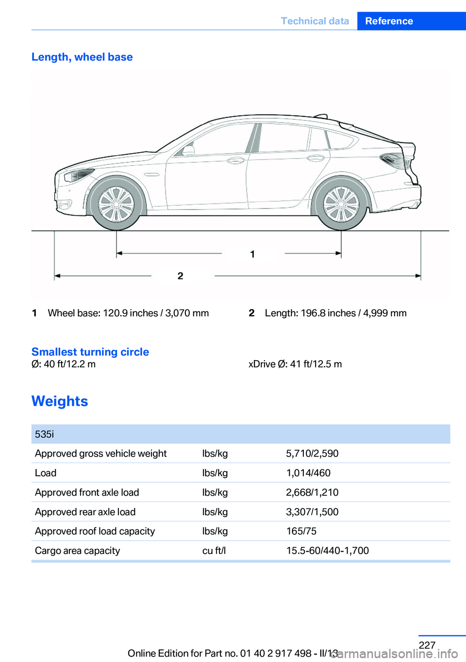
Length, wheel base1Wheel base: 120.9 inches / 3,070 mm2Length: 196.8 inches / 4,999 mm
Smallest turning circle
Ø: 40 ft/12.2 mxDrive Ø: 41 ft/12.5 m
Weights
535iApproved gross vehicle weightlbs/kg5,710/2,590Loadlbs/kg1,014/460Approved front axle loadlbs/kg2,668/1,210Approved rear axle loadlbs/kg3,307/1,500Approved roof load capacitylbs/kg165/75Cargo area capacitycu ft/l15.5-60/440-1,700Seite 227Technical dataReference227
Online Edition for Part no. 01 40 2 917 498 - II/13
Page 228 of 240
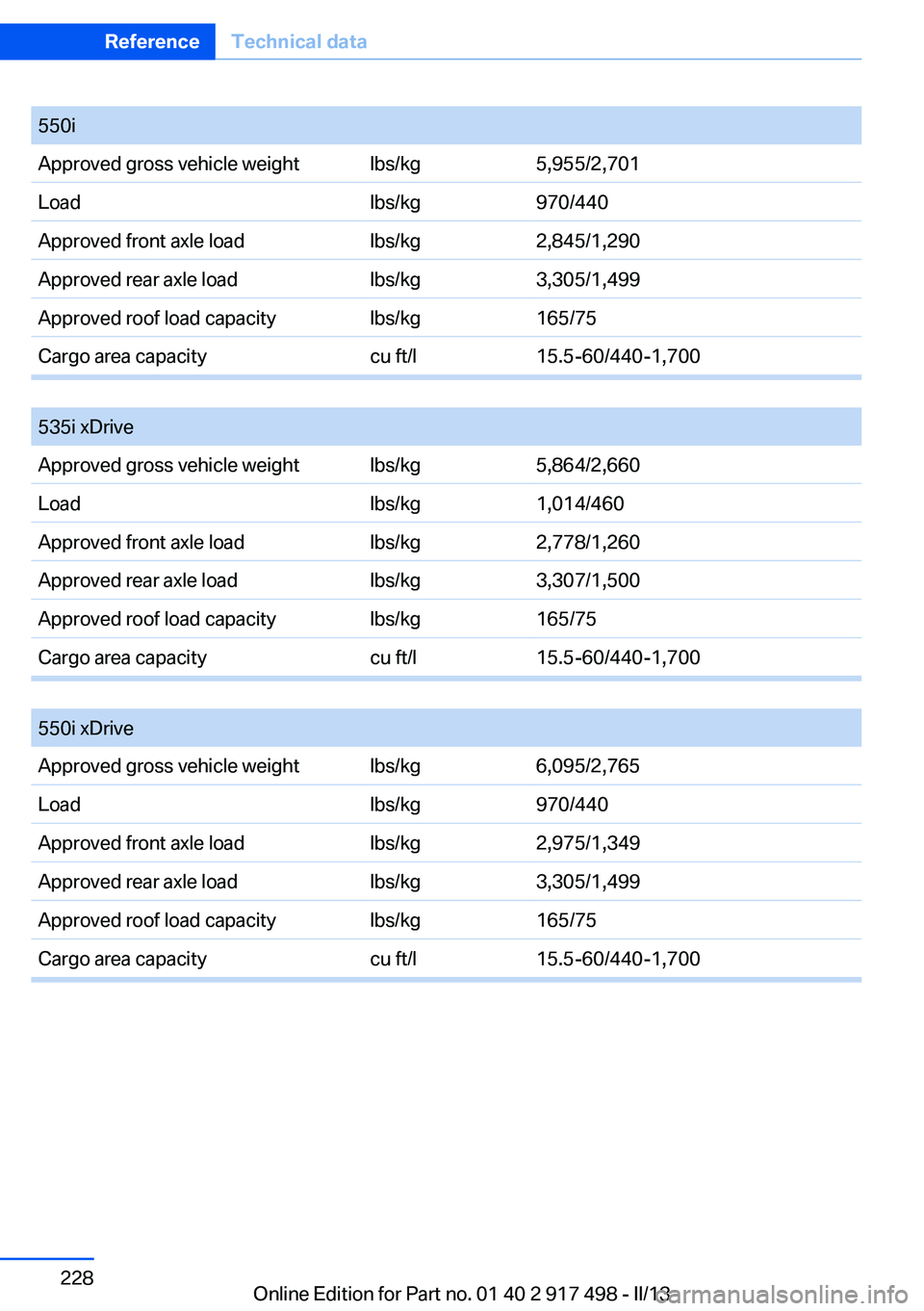
550iApproved gross vehicle weightlbs/kg5,955/2,701Loadlbs/kg970/440Approved front axle loadlbs/kg2,845/1,290Approved rear axle loadlbs/kg3,305/1,499Approved roof load capacitylbs/kg165/75Cargo area capacitycu ft/l15.5-60/440-1,700
535i xDriveApproved gross vehicle weightlbs/kg5,864/2,660Loadlbs/kg1,014/460Approved front axle loadlbs/kg2,778/1,260Approved rear axle loadlbs/kg3,307/1,500Approved roof load capacitylbs/kg165/75Cargo area capacitycu ft/l15.5-60/440-1,700
550i xDriveApproved gross vehicle weightlbs/kg6,095/2,765Loadlbs/kg970/440Approved front axle loadlbs/kg2,975/1,349Approved rear axle loadlbs/kg3,305/1,499Approved roof load capacitylbs/kg165/75Cargo area capacitycu ft/l15.5-60/440-1,700Seite 228ReferenceTechnical data228
Online Edition for Part no. 01 40 2 917 498 - II/13
Page 230 of 240
Everything from A to Z
IndexA
ABS, Antilock Brake Sys‐ tem 122
ACC, Active Cruise Control with Stop & Go 130
Activated-charcoal filter 155
Active Blind Spot Detec‐ tion 118
Active Cruise Control with Stop & Go, ACC 130
Active Protection 120
Active seat, front 52
Active seat ventilation, front 52
Active seat ventilation, rear 55
Active Steering, integral 125
Adaptive brake assistant 122
Adaptive brake lights, refer to Brake force display 120
Adaptive drive 125
Adaptive light control 99
Additives, oil 204
Adjust front seat 49
Adjustments, seats/head re‐ straints 49
After washing vehicle 221
Airbags 102
Airbags, indicator/warning light 103
Air circulation, refer to Recir‐ culated-air mode 154
Air, dehumidifying, refer to Cooling function 154
Air distribution, manual 153
Air flow, automatic climate control 153
Air pressure, tires 191
Air vents, refer to Ventila‐ tion 155 Alarm system 43
Alarm, unintentional 44
All around the center con‐ sole 14
All around the headliner 15
All around the steering wheel 12
ALL program, automatic cli‐ mate control 154
All-season tires, refer to Win‐ ter tires 198
All-wheel-drive 124
Alternating-code hand-held transmitter 160
Alternative oil types 204
Ambient light 101
Antifreeze, washer fluid 78
Antilock Brake System, ABS 122
Anti-slip control, refer to DSC 122
Approved axle load 227
Approved engine oils 204
Armrest, refer to Center arm‐ rest 168
Arrival time 93
Ashtray 161
Assistance, Roadside Assis‐ tance 216
Assistance when driving off 122
AUTO H button, refer to Auto‐ matic Hold 74
AUTO intensity 153
Automatic car wash 220
Automatic climate con‐ trol 152
Automatic Cruise Control with Stop & Go 130
Automatic Curb Monitor 60 Automatic deactivation, front
passenger airbags 104
Automatic headlamp con‐ trol 98
Automatic Hold 74
Automatic locking 37
Automatic recirculated-air control 154
Automatic Soft Closing, doors 38
Automatic Soft Closing, tail‐ gate 39
Automatic tailgate 39
Automatic transmission with Steptronic 78
AUTO program, automatic cli‐ mate control 153
AUTO program, intensity 153
Auto Start/Stop function 70
Average fuel consumption 93
Average speed 93
Axle loads, weights 227
B
Backrest curvature, refer to Lumbar support 51
Backrest, width 51
Back seats, adjusting 53
Backup camera 140
Band-aids, refer to First aid kit 216
Bar for tow-starting/tow‐ ing 218
Basic position, rear seats 55
Battery replacement, vehicle battery 212
Battery replacement, vehicle remote control 31
Battery, vehicle 212
Belts, safety belts 56 Seite 230ReferenceEverything from A to Z230
Online Edition for Part no. 01 40 2 917 498 - II/13