Cluster BMW 540i 1997 E39 Owner's Manual
[x] Cancel search | Manufacturer: BMW, Model Year: 1997, Model line: 540i, Model: BMW 540i 1997 E39Pages: 1002
Page 550 of 1002
Downloaded from www.Manualslib.com manuals search engine
21 0-8
Clutch
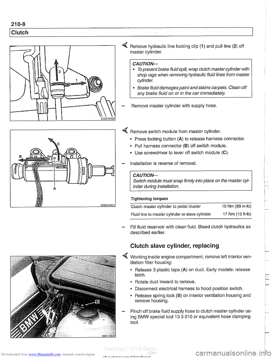
4 Remove hydraulic line locking clip (1) and pull line (2) off
master cylinder.
CAUTION-
. To prevent brake fluidspill, wrap clutch master cylinder with
shop rags when removing hydraulic fluid lines from master
cylinder.
* Brake fluid damages paint andstains carpets. Clean off
any brake fluid on or
in the car immediately.
- Remove master cylinder with supply hose
4 Remove switch module from master cylinder.
Press locking button
(A) to release harness connector.
Pull harness connector
(8) off switch module.
Use screwdriver to lever
off switch module (C).
- Installation is reverse of removal.
CA UTlON-
Switch module must snap firmly into place on the master cyl-
inder during installation.
Tightening torques
Clutch master cylinder to pedal cluster
10 Nm (89 in-lb)
Fluid line
to master cylinder or slave cylinder 17 Nm (13 ft-lb)
- Fill fluid reservoir with clean fluid. Bleed clutch hydraulics as
described earlier.
Clutch slave cylinder, replacing
4 Working inside engine compartment, remove left interiorven-
tilation filter housing:
Release
3 plastic taps (A) on duct. Early models: release
latch.
Rotate duct inward to remove.
Disconnect electrical harness to hood position switch.
Release spring lock (B) on interior ventilation housing and
remove housing.
- Pinch off brake fluid supply hose to clutch master cylinder us-
ing BMW special tool
13 3 01 0 or equivalent hose clamping
tool.
Page 563 of 1002
Downloaded from www.Manualslib.com manuals search engine
Self-adjusting clutch (SAC), breaking in
With normal driving, 800 to 1000 gearshifts are required to
break in the clutch.
Break in the SAC gradually, with light to medium loads, to en-
sure correct operation and long life. Fast sports driving ma-
neuvers may destroy a new
clutch.The following break-in
procedure helps to create the correct coefficient of friction.
Drive normally on level grade. Starting speeds on level
grade may be up to 2000 rpm.
Upshift and downshift through all the gears at 3500
- 4000
rpm.
On medium grades (approx. 12% and up), start
off at ap-
prox. 2500 rpm for the first 5 or so times.
Tightening torques
Clutch slave cylinder to transmission case 22 Nm (16 It-lb)
Clutch master cylinder to pedal cluster 10 Nm (89 in-lb)
Bralte fluid line to clutch master or slave cylinder 17 Nm (13 ft-lb)
Transmission to engine
M8 (Torx) 22 Nm (16 fl-lb)
. M1O (Torx) 43 Nm (32 ft-lb)
MI2 (Torx) 72 Nm (53 it-lb)
Flywheel to crankshaft
6 cylinder engine (use new self-loclting bolts) 105 Nm (77 ft-lb)
V-8 engine 105 Nm (77 ft-lb)
Clutch to flywheel
M8 (8.8 grade)
M8 (10.9 grade) 24
Nm
(18 ft-lb)
34 Nm (25 ft-lb)
Page 804 of 1002
Downloaded from www.Manualslib.com manuals search engine
400-1 0
Body-General
Seats
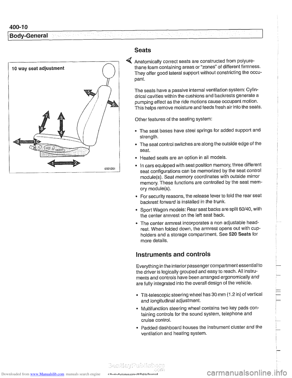
4 Anatomically correct seats are constructed from polyure-
10 way seat adjustment thane foam
containing areas or "zones" of different firmness.
They offer good lateral support without constricting the occu-
pant.
The seats have a passive internal ventilation system: Cylin-
drical cavities within the cushions and backrests generate a
pumping effect as the ride motions cause occupant motion.
This
helps remove moisture and feeds fresh air into the seats.
Other features of the seating system:
The seat bases have steel springs for added support and
strength.
The seat control switches are along the outside edge of
the
seat.
Heated seats are an option in all models
In cars equipped with seat position memory, three different
seat confiaurations can be memorized by the seat control
module(s): Seat memory coordinates with outside mirror
memory. These functions are controlled by the seat mem-
ory
module(s).
* For security reasons, the release lever to fold the rear seat
backrest forward is installed in the trunk.
Sport Wagon models: Rear seat
baclts are split 60140, with
the center armrest on the left seat back.
The center armrest incorporates a non adjustable head-
rest. When folded down, the armrest opens out with
cup-
holders and a storage compartment. See 520 Seats for
more details.
instruments and controls
Everything in the interior passengercompartment essential to
the driver is logically grouped and easy to reach. All instru-
ments and controls have been arranged ergonomically and
are fully integrated into the overall design of the vehicle.
Tilt-telescopic steering wheel has
30 mm (1.2 in) of vertical
and longitudinal adjustment.
Multifunction steering wheel contains two
ltey pads con-
taining controls for the sound system, telephone and
cruise control.
Padded dashboard houses the instrument cluster and the
ventilation and heating system.
Page 805 of 1002
Downloaded from www.Manualslib.com manuals search engine
Instrument cluster
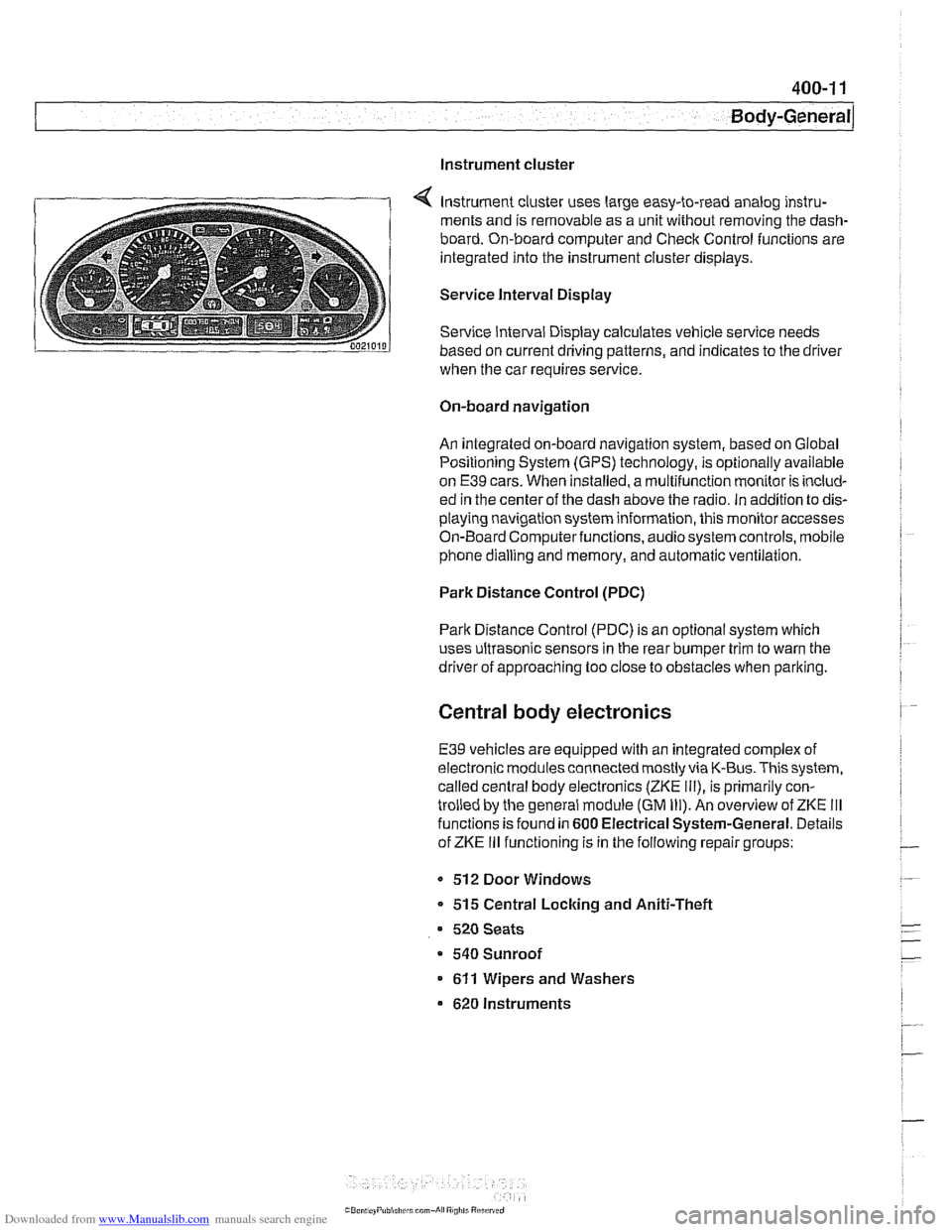
Instrument cluster uses large easy-to-read analog instru-
ments and is removable as a unit without removing the dash-
board. On-board computer and Check Control functions are
integrated into the instrument cluster displays.
Service Interval Display
Service Interval Display calculates vehicle service needs
based on current driving patterns, and indicates to the driver
when the car requires
service
On-board navigation
An integrated on-board navigation system, based on Global
Positioning System (GPS) technology, is optionally available
on
E39 cars. When installed, a multifunction monitor is includ-
ed in the center of the dash above the radio. in addition to dis-
playing navigation system information, this monitor accesses
On-Board Computerfunctions, audiosystem controls, mobile
phone dialling and memory, and automatic ventilation.
Park Distance Control (PDC)
Park Distance Control (PDC) is an optional system which
uses ultrasonic sensors in the rear bumper trim to warn the
driver of approaching too close to obstacles when parlting.
Central body electronics
E39 vehicles are equipped with an integrated complex of
electronic modules connected mostly via K-Bus. This system,
called central body electronics (ZKE
Ill), is primarily con-
trolled by the general module (GM
Ill). An overview of ZKE Ill
functions is found in 600 Electrical System-General. Details
of ZKE
Ill functioning is in the following repair groups:
- 512 Door Windows
* 515 Central Locking and Aniti-Theft
520 Seats
a 540 Sunroof
611 Wipers and Washers
620 Instruments
Page 885 of 1002
Downloaded from www.Manualslib.com manuals search engine
Interior Trim
The E39 dashboard assembly includes the instrument clus-
ter, passenger side
airbag, glove compartment, fuse and re-
lay panel, radio. IHKA control panel oron-board monitor (if
equipped with GPS). The dash is made up of an upper and
lower sections. The lower section must be remove before the
upper section can be removed.
Dashboard removal is a complex operation. Read the proce-
dures through before starting work.
Lower dash panel assembly, removing and
installing
- Disconnect negative (-) cable from battery and cover termi-
nal with
insulating material.
--7
CAUTION-
Prior to disconnecting the battery, read the battery discon-
nectioncautionsgiven atthe irontin001 General Warnings
and Cautions.
- Place steering column in down and extended position.
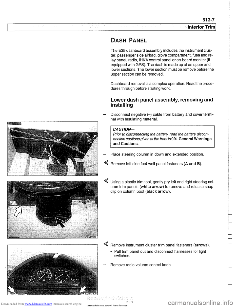
4 Remove left side foot well panel fasteners (A and B).
< Using a plastic trim tool, gently pry left and right steering col-
umn trim panels (white arrow) to remove and release snap
clip on column boot
(black arrow).
I 1 < Remove instrument cluster trim panel fasteners (arrows).
Pull trim panel out and disconnect harnesses for light
switches.
- Remove radio volume control knob.
Page 888 of 1002
Downloaded from www.Manualslib.com manuals search engine
interior Trim
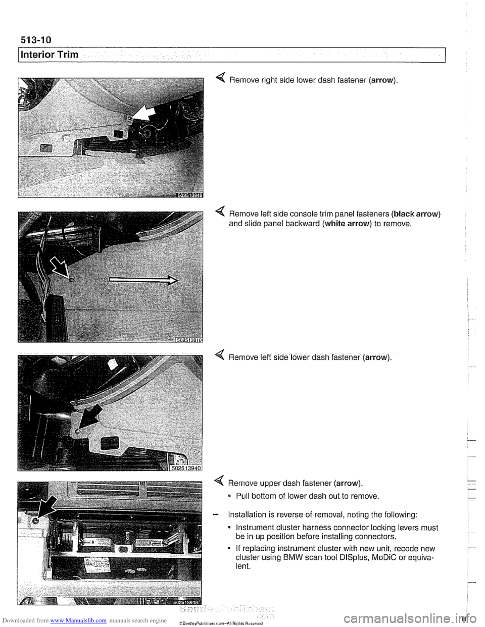
Remove right side lower dash fastener (arrow)
< Remove left side console trim panel fasteners (black arrow)
and slide panel backward (white arrow) to remove.
4 Remove left slde lower dash fastener (arrow)
4 Remove upper dash fastener (arrow).
- Pull bottom of lower dash out to remove
- Installation is reverse of removal, noting the following:
Instrument cluster harness connector
loclting levers must
be in up position before installing connectors.
If replacing instrument cluster with new unit,
recode new
cluster using
BMW scan tool DISplus, MoDiC or equiva-
lent.
Page 889 of 1002
Downloaded from www.Manualslib.com manuals search engine
Interior ~riml
Upper dash assembly, removing and
installing
- Remove lower dash assembly. See Lower dash panel as-
sembly, removing and installing.
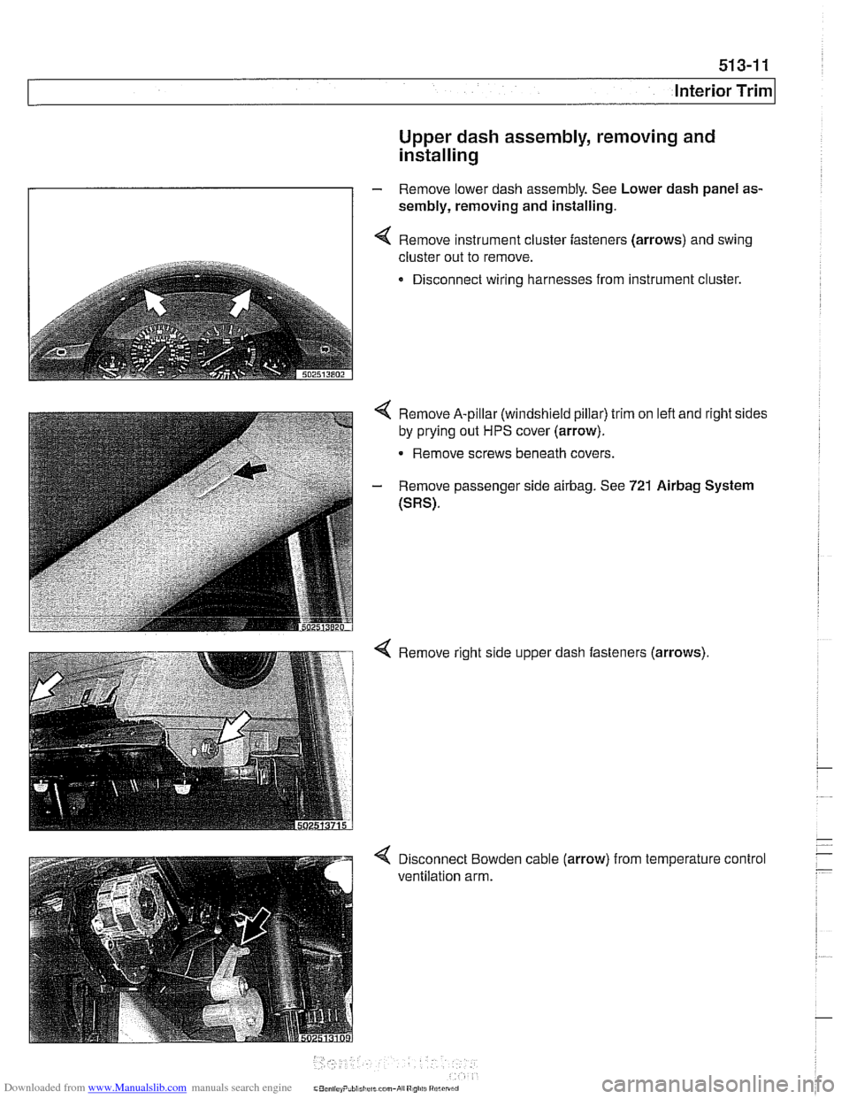
I I 4 Remove instrument cluster fasteners (arrows) and swing
cluster out to remove.
Disconnect wiring harnesses from instrument cluster.
4 Remove A-pillar (windshield pillar) trim on left and right sides
by prying out
HPS cover (arrow).
- Remove screws beneath covers.
- Remove passenger side airbag. See 721 Airbag System
(SRS).
Page 904 of 1002
Downloaded from www.Manualslib.com manuals search engine
1 Central Locking and Anti-Theft
NOJE-
A single unlock request from the driver's door with the FZV
key unlocks the driver's door only.
A second unlock request
unlocls the remaining doors and trunk. This feature can be
modified for individual users with the Key Memory capabil-
ities to activate all lock actuators simultaneously See Car
Memory
/ Key Memory later in this section.
Starting with 2000 models, the battery in the FZV ignition
Icey is recharged by the ignition switch ring antenna while
the ley is in the ignition switch.
Transmitter self-test (models to
1999)
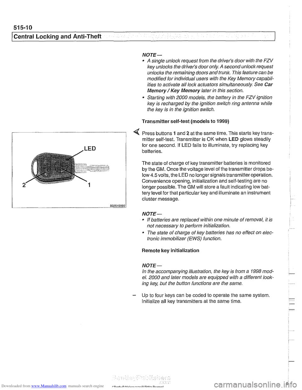
Press buttons 1 and 2 at the same time. This starts ltey trans-
/ mitter self-test. Transmitter is OK when LED glows steadily
te{le"el for that particular key and illuminate an instrument
cluster message.
-- 502515092 J
NO JE-
If batteries are replaced within one minute of removal, it is
not necessary to
periorm initialization.
Tlie state of charge of key batteries has no effect on elec-
tronic immobilizer (EWS) function.
2
Remote key initialization
for one second. If LED fails to illuminate, try replacing ltey~
batteries.
The state of charge of key transmitter batteries is monitored
by the
GM. Once the voltage level of the transmitter drops be-
low
4.5volts, the LED no longersignals transmitteroperation.
Convenience opening, initialization and self-testing are no
lonaer ~ossible. The GM will store a fault indicatina low bat-
NOJE-
In the accompanying illustration, the key is from a 1998 mod-
el. 2000 and later models are equipped with a different look-
ing
/
Initialize all key transmitters at the same time.
Page 906 of 1002
Downloaded from www.Manualslib.com manuals search engine
51 5-12
I Central Locking and Anti-Theft
Key battery
9
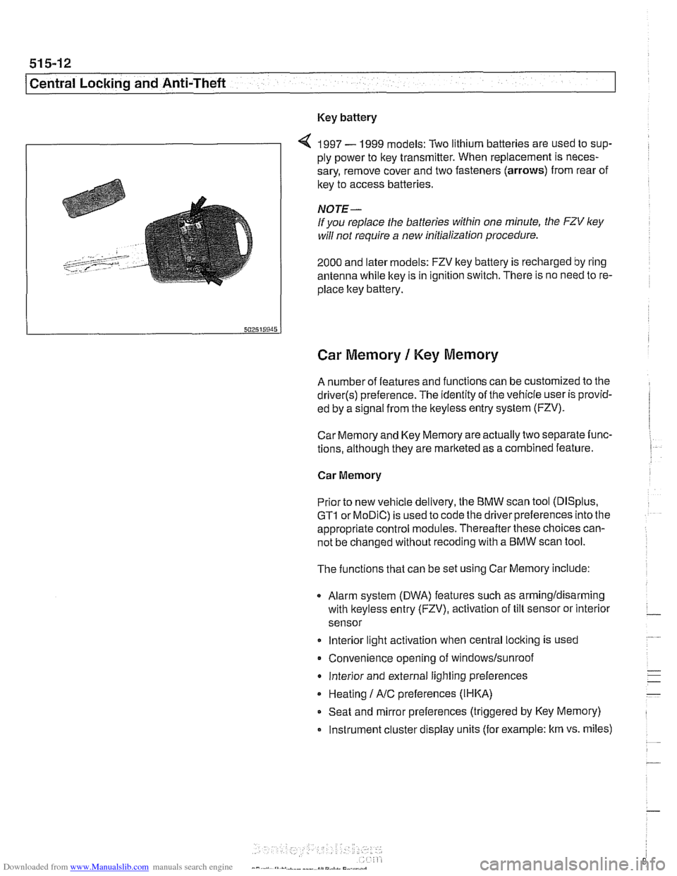
4 1997 - 1999 models: Two lithium batteries are used to sup-
ply power to key transmitter. When replacement is neces-
sary, remove cover and two fasteners (arrows) from rear of
key to access batteries
NOTE-
If you replace the batteries within one minute, the FZV ley
will not require a new initialization procedure.
2000 and later models: FZV key battery is recharged by ring
antenna while ltey is in ignition switch. There is no need to re-
place ltey battery.
Car Memory 1 Key Memory
A number of features and functions can be customized to the
driver(s) preference. The identity of the vehicle user is provid-
ed by a
s~gnal from the keyless entry system (FZV).
Car Memory and Key Memory are actually two separate func-
tions, although they are marketed as a combined feature.
Car Memory
Pr'or ro new
veh c,e de very, the BMW scan roo (DISp us,
GTI or MOD C) is ~sed lo cooc ine driver preierences nro ine
appropriate control modules. Thereafter these choices can-
not be changed without
recoding with a BMW scan tool.
The functions that can be set using Car Memory include:
Alarm system (DWA) features such as armingldisarming
with
lkeyless entry (FZV), activation of tilt sensor or interior
sensor
lnterior light activation when central
locking is used
Convenience opening of
windows/sunroof
lnterior and external lighting preferences
Heating
I A/C preferences (IHKA)
Seat and mirror preferences (triggered by Key Memory)
Instrument cluster display units (for example: km vs. miles)
Page 952 of 1002
Downloaded from www.Manualslib.com manuals search engine
I Airbag System (SRS)
Two-stage airbag (MRS Ill)
Beginning with 2000 model year (911 999 production) the front
airbags were changed to a two-stage style airbag. This en-
sures that the force of
airbag inflation is not greater than nec-
essary to provide
protection. The airbags are designed to
Drovide "soit" de~lovment if the acceleration sensor detects a
iow-speed impact, and "hard deployment in higher speed im-
pacts.
NOTE-
A two-stage passenger airbag was used on cars built be-
tween
9/1998 and 3/1999. This pre-smart technology airbag
used two ignition stages. Stage one is designed to ignite first
during an impact. Stage two ignites after a timed period, as
programmed in the MRS
I1 control module.
Airbag indicator light
The MRS control module detects and stores system status
The
airbag indicator light in the instrument cluster displays
the status of the
airbag system when the ignition key is in "ac-
cessory" or
ON positions.
System normal: lndicator light comes on briefly, then goes
out.
- System malfunction: lndicator light fails to come on.
System malfunction: lndicator light comes on briefly, goes
out and lights up again.
The
airbag indicator light also comes on if the seat belt pyro-
technic tensioners have been triggered.