locking BMW 540i 1998 E39 Workshop Manual
[x] Cancel search | Manufacturer: BMW, Model Year: 1998, Model line: 540i, Model: BMW 540i 1998 E39Pages: 1002
Page 905 of 1002
Downloaded from www.Manualslib.com manuals search engine
515-11
Central Lockinq and ~nti-l heft/
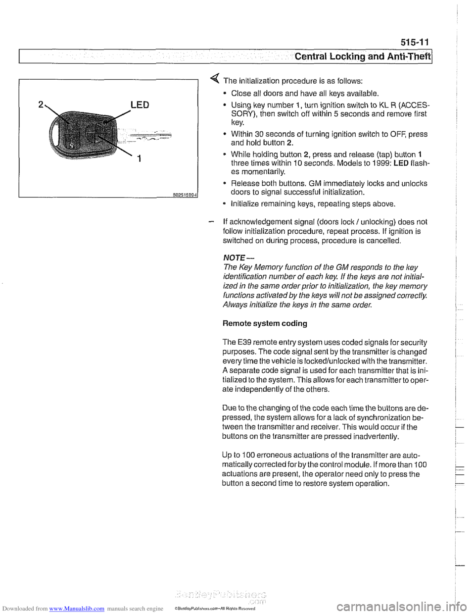
4 The initialization procedure is as follows:
Close ail doors and have all keys available
2 LED Using lkey number I, turn ignition switch to KL R (ACCES-
SORY), then switch off within 5 seconds and remove first
key.
. - -- , ..-.---- - Within 30 seconds of turning ignition switch to OFF, press
and hold button
2.
1 While holding button 2, press and release (tap) button 1
three times within 10 seconds. Models to 1999: LED flash-
- If acknowledgement signal (doors lock / unlocking) does not
follow initialization procedure, repeat process. If ignition is
switched on during process, procedure is cancelled.
50251509‘1
NOTE-
The Key Memory function of the GM responds to the ley
identification number of each key If the keys are not initial-
ized
in the same orderprior to initialization, the ley memory
functions activated by the
l(eys will not be assigned correctly.
Always initialize the keys
in the same order.
es momentarily.
Release both buttons. GM immediately locks and unlocits
doors to signal successful initialization.
Remote system coding
* Initialize remaining lteys, repeating steps above.
The E39 remote entry system uses coded signals for security
purposes. The code signal sent by the transmitter is changed
every time the vehicle is lockedlunlocked with the transmitter.
A separate code signal is used for each transmitter that is ini-
tialized to the system. This allows for each transmitterto oper-
ate independently of the others.
Due to the changing of the code each time the buttons are de-
pressed, the system allows for a
lacit of synchronization be-
tween the transmitter and receiver. This would occur
if the
buttons on the transmitter are pressed inadvertently.
Up to
100 erroneous actuations of the transmitter are auto-
matically corrected
forby the control module. If more than 100
actuations are present, the operator need only to press the
button a second time to restore system operation.
Page 906 of 1002
Downloaded from www.Manualslib.com manuals search engine
51 5-12
I Central Locking and Anti-Theft
Key battery
9
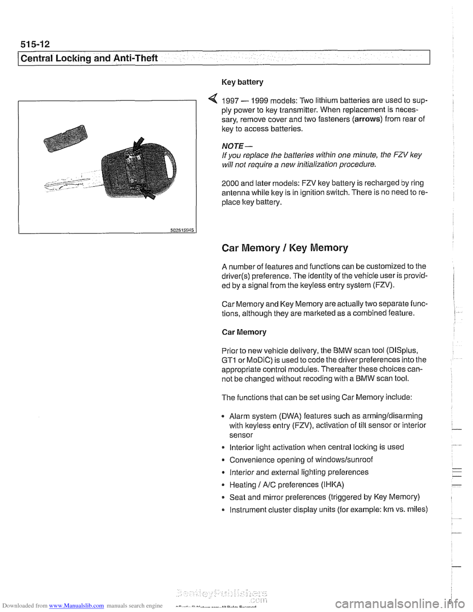
4 1997 - 1999 models: Two lithium batteries are used to sup-
ply power to key transmitter. When replacement is neces-
sary, remove cover and two fasteners (arrows) from rear of
key to access batteries
NOTE-
If you replace the batteries within one minute, the FZV ley
will not require a new initialization procedure.
2000 and later models: FZV key battery is recharged by ring
antenna while ltey is in ignition switch. There is no need to re-
place ltey battery.
Car Memory 1 Key Memory
A number of features and functions can be customized to the
driver(s) preference. The identity of the vehicle user is provid-
ed by a
s~gnal from the keyless entry system (FZV).
Car Memory and Key Memory are actually two separate func-
tions, although they are marketed as a combined feature.
Car Memory
Pr'or ro new
veh c,e de very, the BMW scan roo (DISp us,
GTI or MOD C) is ~sed lo cooc ine driver preierences nro ine
appropriate control modules. Thereafter these choices can-
not be changed without
recoding with a BMW scan tool.
The functions that can be set using Car Memory include:
Alarm system (DWA) features such as armingldisarming
with
lkeyless entry (FZV), activation of tilt sensor or interior
sensor
lnterior light activation when central
locking is used
Convenience opening of
windows/sunroof
lnterior and external lighting preferences
Heating
I A/C preferences (IHKA)
Seat and mirror preferences (triggered by Key Memory)
Instrument cluster display units (for example: km vs. miles)
Page 907 of 1002
Downloaded from www.Manualslib.com manuals search engine
- -
Central Locking and ~nti-~hefil
Key Memory
Whenever one of the FZV keys is used to lock or unlock the
car, the user is identified by the GM. A maximum of four
keys
can be programmed with the Key Memoryfeature. The use of
the personalized key then triggers Car Memory functions
such as heating
I AIC (IHKA) settings or memory seat position
adjustment.
Most programming of Key Memory requires the use of
BMW
scan tools (DISplus, GT1 or MoDiC). However, features such
as
IHKA blower speed and temperature store automatically
without the use of scan tools.
Available Key Memory functions vary based on vehicle equip-
ment. The functions that can be set include:
Automatic locking after start off (vehicle speed)
Selective locking
Heating
1 AJC blower speed, heated or cooled air distribu-
tion, automatic blower setting
Trunk lid soft close (SCA)
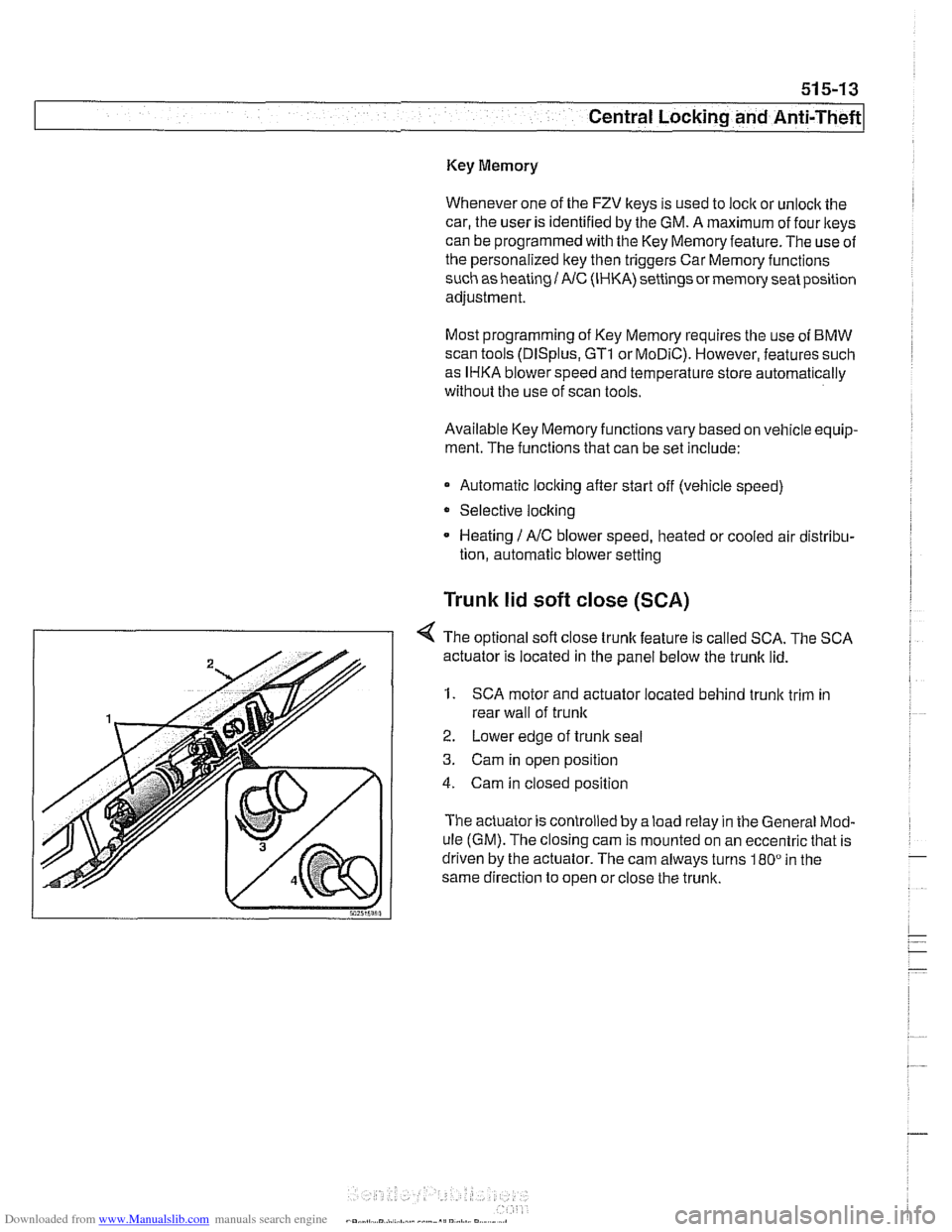
< The optional sofl close trunk feature is called SCA. The SCA
actuator is located in the panel below the trunk lid.
1. SCA motor and actuator located behind trunk trim in
rear wall of
trunlc
2. Lower edge of trunlc seal
3. Cam in open position
4. Cam in closed position
The actuator is controlled by a load relay in the General Mod-
ule (GM). The closing cam is mounted on an eccentric that is
driven by the actuator. The cam always turns
180" in the
same direction to open or close the trunk.
Page 909 of 1002
Downloaded from www.Manualslib.com manuals search engine
51 5-1 5
Central Locking and Anti-Theft
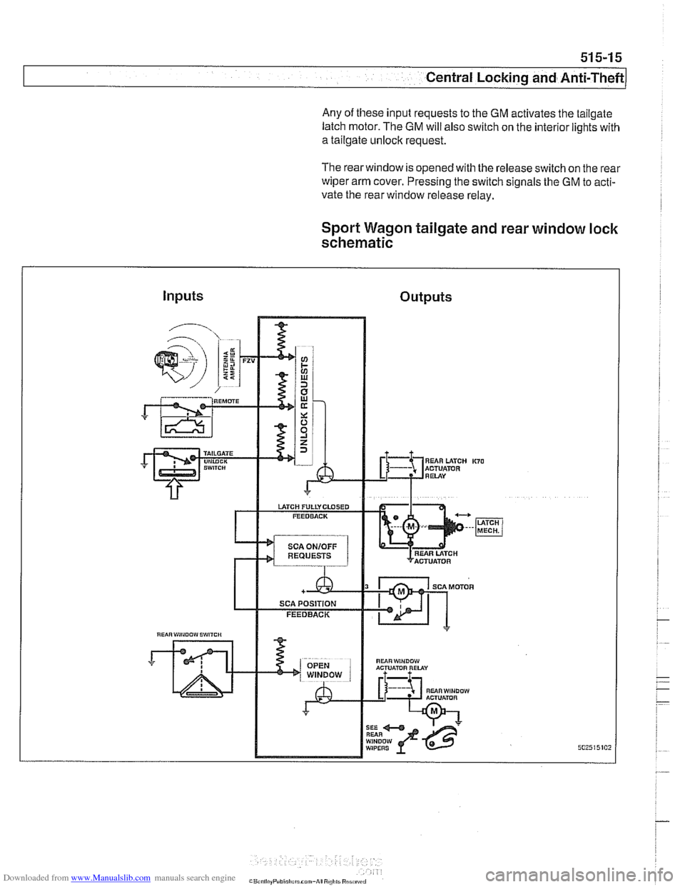
Any of these input requests to the GM activates the tailgate
latch motor. The
GM will also switch on the interior lights with
a tailgate unlock request.
The rearwindow is opened with the release switch on the rear
wiper arm cover. Pressing the switch signals the GM to acti-
vate the rear window release relay.
Sport Wagon tailgate and rear window lock
schematic
Inputs Outputs
"UiRWiNOOW ACTUATOR RELAY
RUiRWINDOW ACTUlimR A L
WIPERS
Page 910 of 1002
Downloaded from www.Manualslib.com manuals search engine
51 5-1 6
Central Locking and Anti-Theft
DOOR HANDLES AND LOCKS
In the procedures that follow, door handle removal, door lock
cylinder removal and door latch removal are covered for the
left front door. Other doors are similar although simpler, due
to the
lack of lock cylinder.
Inside door release removal is covered in the procedure for
inner door
ane el removal. See 411 Doors.
Door handle (outer), removing and
installing
NOTE-
IfBMWspecial tools 51 3201 and51 3 203 are available, the
door handle can be removed without removing the door trim
panel or door
airbag. Use the access hole behind the rubber
sealing plug on the door edge.
- Close window on front door.
- Disconnect battery negative (-) cable.
CAUTlOG
Prior to disconnecting the batter)! read the battery discon-
nection cautions given
in 001 General Warnings and Cau-
tions.
Remove front door trim panel. See 411 Doors.
Remove door-mounted air bag. See 721
Airbag System
(SRS).
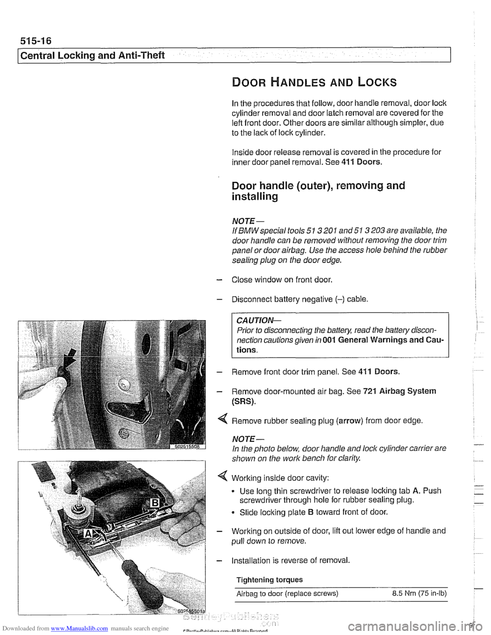
Remove rubber sealing plug (arrow) from door edge
NOTE-
In the photo below, door handle and lock cylinder carrier are
shown on the work bench for clarity.
Working inside door cavity:
- Use long thin screwdriver to release locking tab A. Push
screwdriver through hole for rubber sealing plug.
Slide locking plate
B toward front of door.
Working on outside of door, lift out lower edge of handle and
pull down to remove.
Installation is reverse of removal,
Tightening torques
Airbag to door (replace screws) 8.5 Nrn (75 in-lb)
Page 911 of 1002
Downloaded from www.Manualslib.com manuals search engine
Central Locking and ~nti-~heel
Door latch, removing and installing
- Close window on subject door and open all other windows.
- Disconnect battery negative (-) cable
CAUTION-
Prior to disconnecting the batterl: read the battery discon-
nection cautions given in
001 General Warnings and Cau-
tions.
- Remove door trim panel. See 411 Doors.
- Remove air bag. See 721 Airbag System (SRS).
- Remove outer door handle. See Door handle (outer), re-
moving and installing.
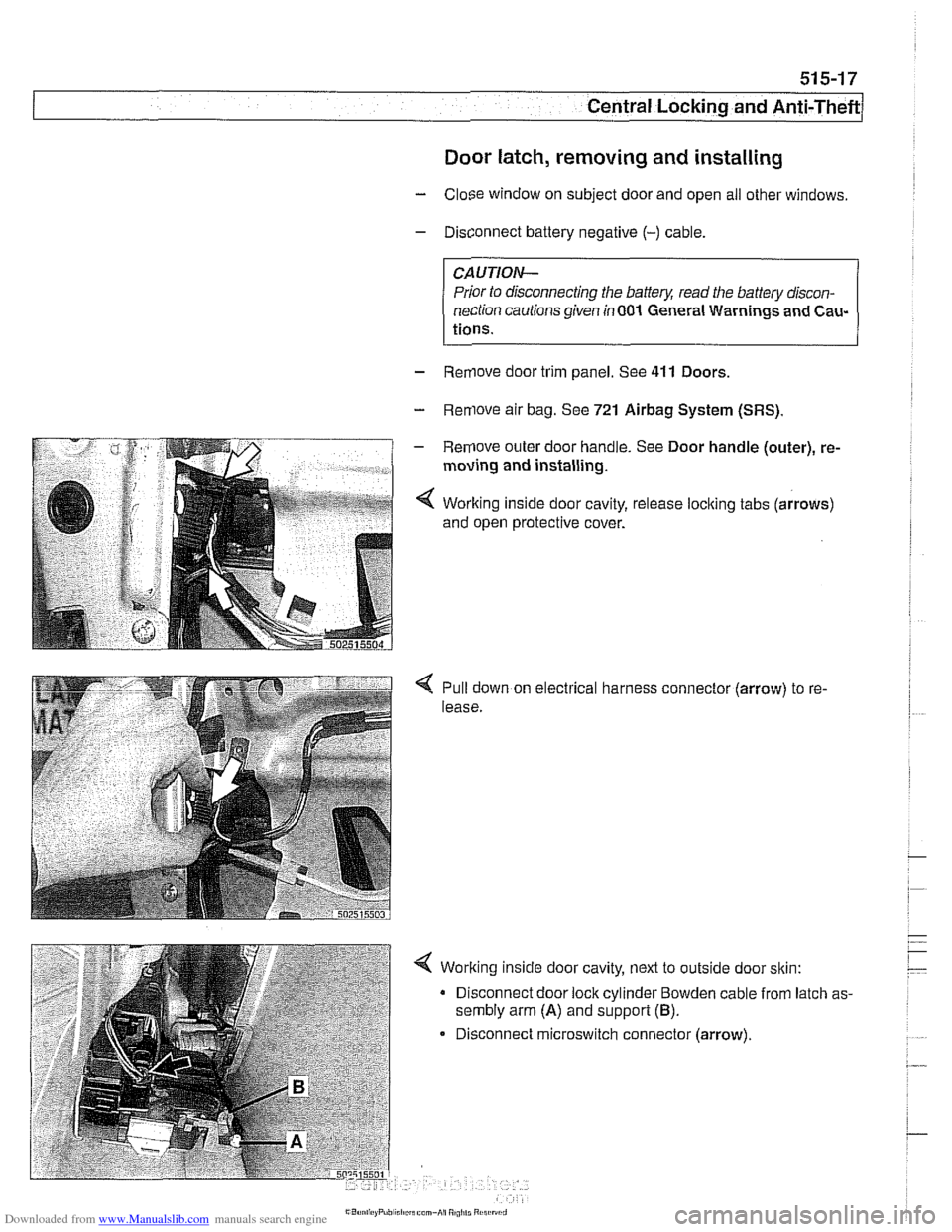
< Working inside door cavity, release loclting tabs (arrows)
and open protective cover.
Pull down on electrical harness connector (arrow) to re-
lease.
< Working inside door cavity, next to outside door sltin:
Disconnect door lock cylinder Bowden cable from latch as-
sembly arm
(A) and support (B).
Disconnect microswitch connector (arrow).
Page 912 of 1002
Downloaded from www.Manualslib.com manuals search engine
51 5-1 8
I Central Locking and Anti-Theft
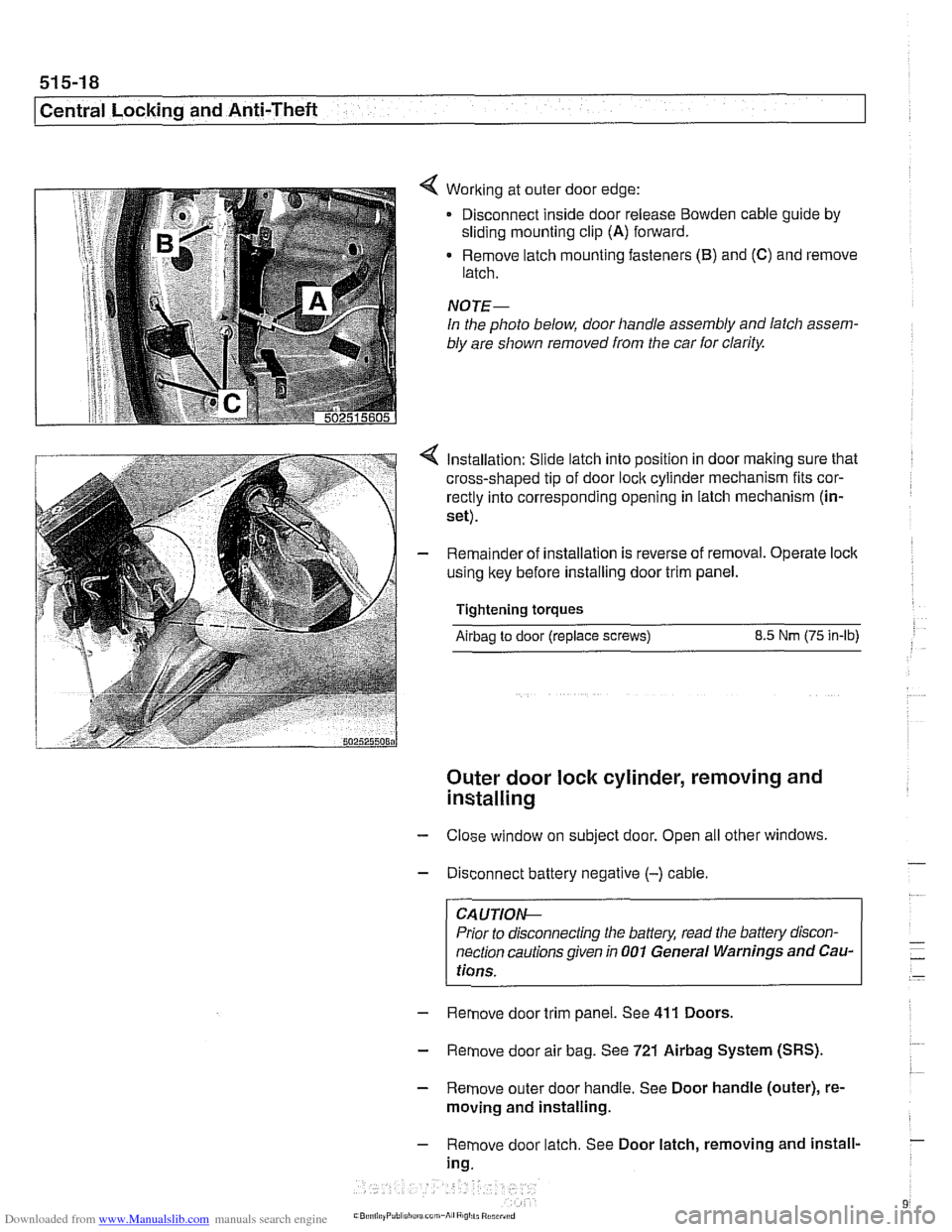
< Working at outer door edge:
Disconnect inside door release
Bowden cable guide by
sliding mounting clip (A) forward.
Remove latch mounting fasteners
(B) and (C) and remove
latch.
NOTE-
In the photo below, door handle assembly and latch assem-
bly are shown removed from the car
for clarity.
Installation: Slide latch into position in door making sure that
cross-shaped tip of door
loclc cylinder mechanism fits cor-
rectly into corresponding opening in latch mechanism (in-
set).
Remainder of installation is reverse of removal. Operate
loclc
using key before installing door trim panel.
Tightening torques
Airbag to door (replace screws) 8.5 Nm (75 in-lb)
Outer door lock cylinder, removing and
installing
- Close window on subject door. Open all other windows
- Disconnect battery negative (-) cable.
CA UTIOIG
Prior to disconnecting the baffeg read the battery discon-
nection cautions given in
001 General Warnings and Cau-
tions.
- Remove door trim panel. See 411 Doors.
- Remove door air bag. See 721 Airbag System (SRS).
- Remove outer door handle. See Door handle (outer), re-
moving and installing.
- Remove door latch. See Door latch, removing and install-
ing.
Page 913 of 1002
Downloaded from www.Manualslib.com manuals search engine
Central Locking and Anti-Theft
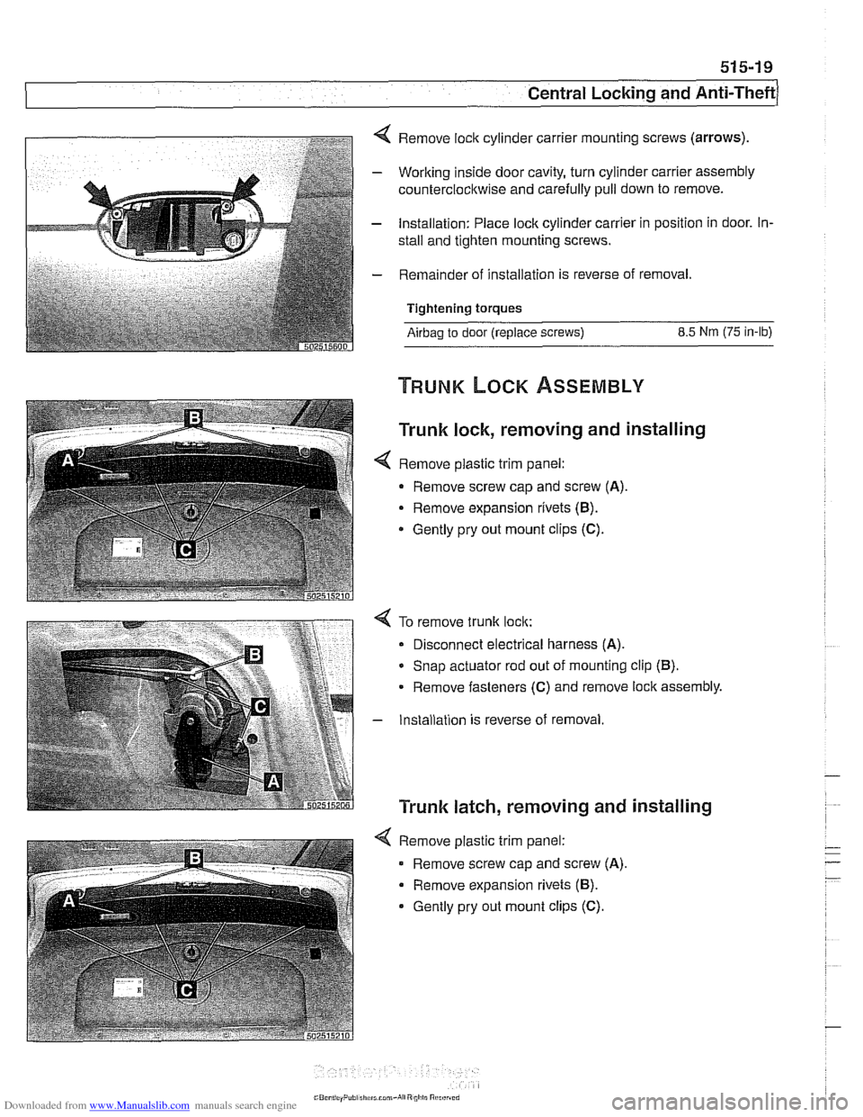
4 Remove lock cylinder carrier mounting screws (arrows).
- Working inside door cavity, turn cylinder carrier assembly
counterclockwise and carefully pull down to remove.
- Installation: Place lock cylinder carrier in position in door. In-
stall and tighten mounting screws.
- Remainder of installation is reverse of removal.
Tightening torques
Airbag to door (replace screws) 8.5 Nm (75 in-lb)
Trunk lock, removing and installing
< Remove plastic trim panel:
- Remove screw cap and screw (A).
Remove expansion rivets (B).
* Gently pry out mount clips (C).
4 To remove trunk lock:
Disconnect electrical harness
(A).
* Snap actuator rod out of mounting clip (B).
Remove fasteners (C) and remove lock assembly.
- Installation is reverse of removal
Trunk latch, removing and installing
4 Remove plastic trim panel:
Remove screw cap and screw
(A).
Remove expansion rivets (B).
Gently pry out mount clips (C).
Page 914 of 1002
Downloaded from www.Manualslib.com manuals search engine
515-20
Central Locking and Anti-Theft
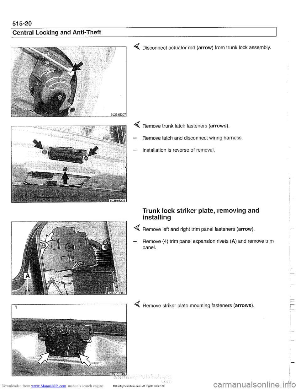
4 Disconnect actuator rod (arrow) from trunk loclc assembly.
4 Remove trunk latch fasteners (arrows).
- Remove latch and disconnect wiring harness.
- Installation is reverse of removal.
Trunk lock striker plate, removing and
installing
4 Remove left and right trim panel fasteners (arrow).
- Remove (4) trim panel expansion rivets (A) and remove trim
panel.
1 4 Remove striker plate mounting fasteners (arrows).
Page 915 of 1002
Downloaded from www.Manualslib.com manuals search engine
51 5-21
Central Locking and Anti-Theft
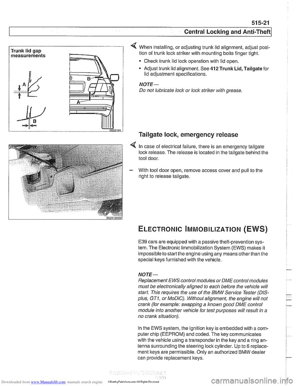
Trunk lid gap
measurements 4 When installing, or adjusting trunk lid alignment, adjust posi-
tion of trunk
loclc striker with mounting bolts finger tight.
* Check trunk lid loclc operation with lid open.
Adjust trunk lid alignment. See
412 Trunk Lid, Tailgate for
lid adjustment specifications.
NOTE-
Do not lubricate lock or lock striker with grease.
Tailgate lock, emergency release
4 In case of electrical failure, there is an emergency tailgate
loclk release. The release is located in the tailgate behind the
tool door.
- With tool door open, remove access cover and pull to the
right to release tailgate.
ELECTRONIC ~MMOBILIZATION (EWS)
E39 cars are equipped with a passive theft-prevention sys-
tem. The Electronic Immobilization System (EWS) makes it
impossible to
startthe engine using any means other than the
special lkeys furnished with the vehicle.
NOTE-
Replacement EWS control modules or DME control modules
must be electronically aligned to each before the vehicle will
start. This requires the use of the BMW Service Tester
(DIS-
plus, GT1, or MoDiC). Without alignment, the engine will not
crank (for example: swapping a
known good DME control
module into another vehicle for test purposes will result in a
no crank situation).
In the EWS system, the ignition key is embedded with
acom-
puter chip (EEPROM) and coded. The key communicates
with the vehicle using a transponder in the lkey and a ring an-
tenna surrounding the steering lock cylinder. Up to
6 replace-
ment keys are permissible. Only an authorized
BMW dealer
can provide replacement keys.