locking BMW 540i 1998 E39 Workshop Manual
[x] Cancel search | Manufacturer: BMW, Model Year: 1998, Model line: 540i, Model: BMW 540i 1998 E39Pages: 1002
Page 769 of 1002
Downloaded from www.Manualslib.com manuals search engine
Brakes
Warnings and cautions
WARNING-
. E39 cars require special BMWsen/ice equipment toprop-
erly bleed the brake hydraulic system. See Bleeding
Brakes for additional information.
Semi-metallic and metallic brake friction materials in
brake pads or shoes may produce dangerous dust.
Brake fluid is poisonous, corrosive and dangerous to
the environment. Wear safety glasses and rubber
gloves when worliing with
bralie fluid. Do not siphon
brake fluid with your mouth. Dispose of brake fluid
properly
Do not reuse self-locking nuts, bolts or fasteners. They
are designed to be used only once and may fail if re-
used. Always replace them with new self-locliing fas-
teners.
CAUTlOI\C
Immediately clean bralie fluid spilled on painted surfaces
and wash with water, as
bralie fluid will remove paint.
Always use new brake fluid from a fresh, unopened
container.
Brake fluid will absorb moisture from the air.
This can lead to corrosion problems in the
braking sys-
tem, and will also lower the fluid boiling point.
. Plug open lines and brake fluid ports to prevent con-
tamination.
Only tighten brake hoses on front wheels
with wheels
in straight ahead position.
If carrying out electric welding
worlc, be sure to discon-
nect electrical harness connector from electronic con-
trol module.
Do not expose electronic control modules to high sus-
tained heat, such as in a paint drying booth. Maximum
heat exposure:-95°C (203
OF) for short periods of time-
85'C (185°F) for Ions periods of time (approx. 2 hours)
Page 771 of 1002
Downloaded from www.Manualslib.com manuals search engine
Brakes
Brakes, bleeding
The procedure below requires a BMW Service Tester (DIS-
pluslGTl/MoDiC).
- Determine type of traction control (ASC, DSC with precharge
pump, DSC without precharge pump). Be sure to use correct
specification brake fluid, according to application table below.
Brake fluid applications
ABS I ASC and ABS / DSC models DOT 4 brake fluid
with precharge pump (to 911998)
ABS I DSC models without precharge DOT 4 low viscosity
pump (911998 and later) brake
fluid
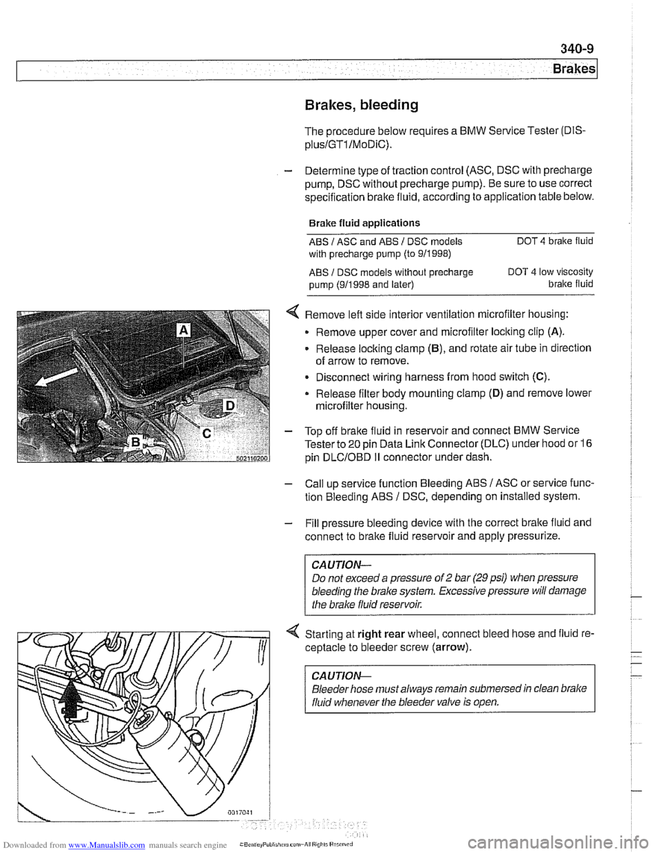
< Remove left side interior ventilation microfilter housing:
Remove upper cover and microfilter loclting clip
(A).
Release locking clamp (B), and rotate air tube in direction
of arrow to remove.
Disconnect wiring harness from hood switch
(C).
Release filter body mounting clamp (D) and remove lower
microfilter housing.
- Top off bralte fluid in reservoir and connect BMW Service
Tester to
20 pin Data Link Connector (DLC) under hood or 16
pin
DLCIOBD I1 connector under dash.
- Call up service function Bleeding ABS / ASC or service func-
tion Bleeding ABS
/ DSC, depending on installed system.
- Fill pressure bleeding device with the correct brake fluid and
connect to brake fluid reservoir and apply pressurize.
Do not exceed a pressure of
2 bar (29 psi) when pressure
bleeding the
brake system. Excessive pressure will damage
4 Starting at right rear wheel, connect bleed hose and fluid re-
ceptacle to bleeder screw (arrow).
CA UTlON-
Bleeder hose must always remain submersed in clean brake
fluid whenever the bleeder valve is open.
Page 779 of 1002
Downloaded from www.Manualslib.com manuals search engine
Brakes
Master cylinder, removing and installing
CAUTlOI\C
Brake fluid is highly corrosive and dangerous to the environ-
ment. Dispose of it properly.
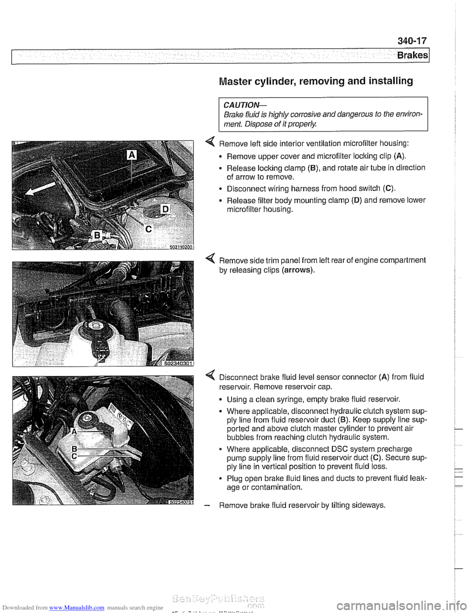
4 Remove left side interior ventilation microfilter housing:
Remove upper cover and microfilter locking clip
(A).
- Release locking clamp (B), and rotate air tube in direction
of arrow to remove.
Disconnect wiring harness from hood switch
(C).
Release filter body mounting clamp (D) and remove lower
microfilter housing.
4 Remove side trim panel from left rear of engine compartment
by releasing clips
(arrows).
4 Disconnect bralte fluid level sensor connector (A) from fluid
reservoir. Remove reservoir cap.
. Using a clean syringe, empty bralte fluid reservoir.
Where applicable, disconnect hydraulic clutch system sup-
ply line from fluid reservoir duct
(5). Keep supply line sup-
ported and above clutch master cylinder to prevent air
bubbles from reaching clutch hydraulic system.
Where applicable, disconnect DSC system precharge
pump supply line from fluid reservoir duct
(C). Secure sup-
ply line in vertical position to prevent fluid loss.
Plug open brake fluid lines and ducts to prevent fluid leak-
age or contamination.
- Remove brake fluid reservoir by tilting sideways.
Page 780 of 1002
Downloaded from www.Manualslib.com manuals search engine
.- -
Brakes
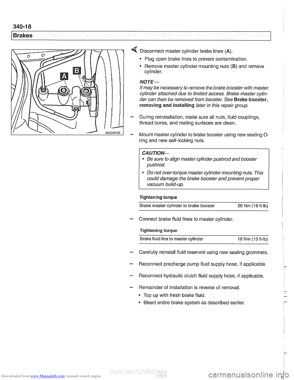
Disconnect master cylinder brake lines (A)
Plug open brake lines to prevent contamination.
Remove master cylinder mounting nuts
(6) and remove
cylinder.
NOTE-
It may be necessary to remove the brake booster with master
cylinder attached due to limited access.
Bralce master cylin-
dercan then be removed from booster. See Brake booster,
removing and installing later
in this repair group.
- During reinstallation, make sure all nuts, fluid couplings,
thread bores, and mating surfaces are clean.
- Mount master cylinder to bralte booster using new sealing O-
ring and new self-locking nuts.
CAUTIOI\C
* Be sure to align master cylinderpushrod and booster
pushrod.
* Do not over-torque master cylinder mounting nuts. This
could damage the brake booster and prevent proper
vacuum build-up.
Tightening torque Brake master cylinder to brake booster
26 Nm (19 ft-lb)
- Connect bralte fluid lines to master cylinder.
Tightening torque Brake fluid line to master cylinder
18 Nm (13 ft-lb)
- Carefully reinstall fluid reservoir using new sealing grommets.
- Reconnect precharge pump fluid supply hose, if applicable. -
- Reconnect hydraulic clutch fluid supply hose, if applicable.
- Remainder of installation is reverse of removal.
Top up with fresh brake fluid.
Bleed entire brake system as described earlier
Page 783 of 1002
Downloaded from www.Manualslib.com manuals search engine
1 Brakes
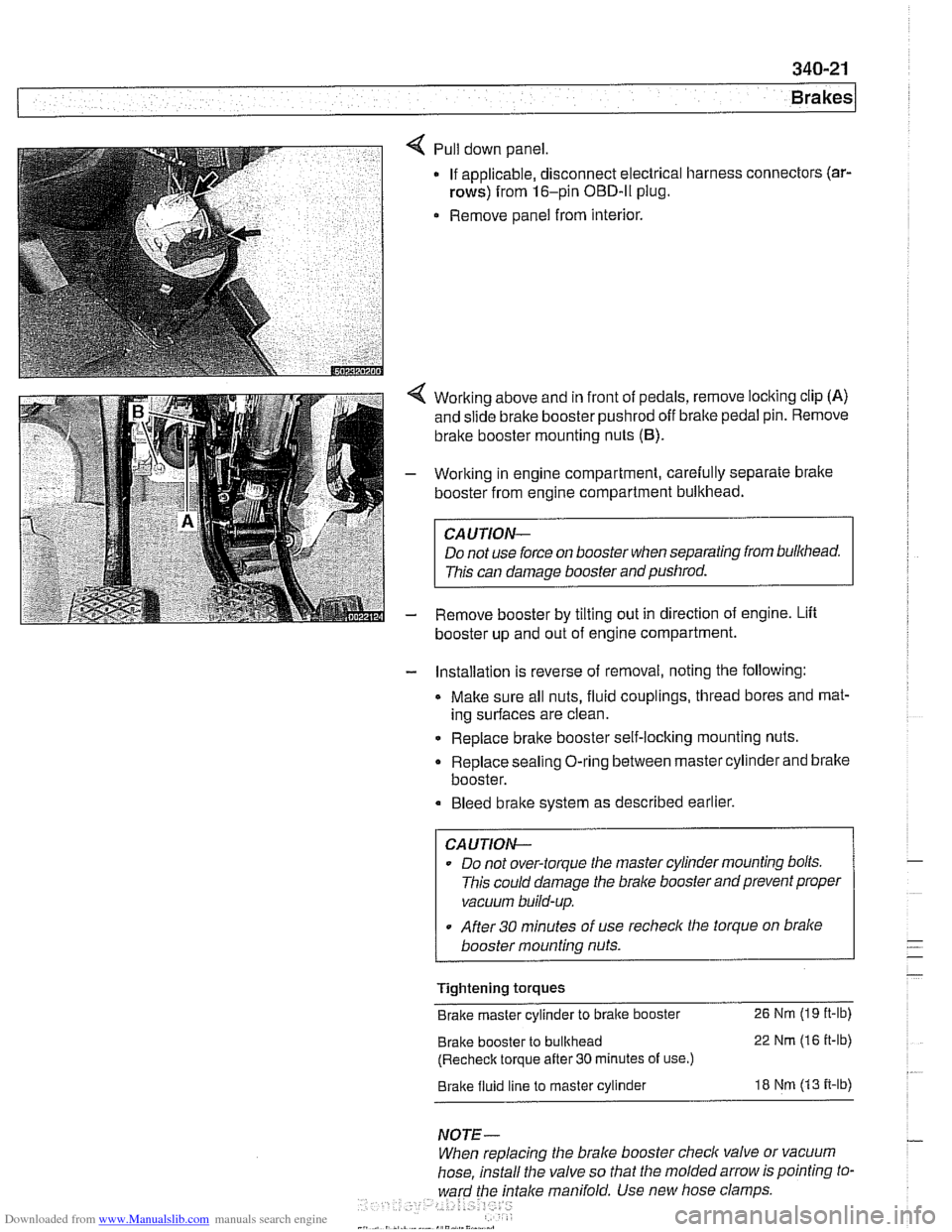
Pull down panel
If applicable, disconnect electrical harness
rows) from 16-pin OBD-ll plug.
Remove panel from interior. connectors
(ar-
Working
above and in front of pedals, remove locking clip (A)
and slide brake booster pushrod off bralte pedal pin. Remove
brake booster mounting nuts
(6).
Working in engine compartment, carefully separate bralte
booster from engine compartment bulkhead.
CAUTION-
Do not use force on booster when separating from bulkhead.
This can damage booster and pushrod.
Remove booster by tilting out in direction of engine. Lift
booster up and out of engine compartment.
- Installation is reverse of removal, noting the following:
Make sure all nuts, fluid couplings, thread bores and mat-
ing surfaces are clean.
Replace bralte booster self-locking mounting nuts.
Replace sealing O-ring between master cylinder and bralte
booster.
Bleed bralte system as described earlier.
CAUTION--
Do not over-torque tlie master cylinder mounting bolts.
This could damage the
bralce booster and prevent proper
vacuum build-up.
After
30 minutes of use recheclc the torque on bralce
booster mounting nuts.
Tightening torques
Brake master cylinder to brake booster
26 Nm (19 it-lb)
Brake booster to bulkhead 22 Nm (16 it-lb)
(Recheck torque after
30 minutes of use.)
Brake fluid line to master cylinder 18 Nm (13 it-lb)
NOTE-
When replacing the brake booster check valve or vacuum
hose, install the valve so that the molded arrow is pointing to-
ward the
fntalce manifold. Use new hose clamps
Page 799 of 1002
Downloaded from www.Manualslib.com manuals search engine
400-5
Body-General
Tailgate
The E39 Sporl Wagon tailgate is large with a low sill for easy
cargo loading. The tailgate opens to an angle of
88" mea-
sured from the rear roof pillar (D-pillar) and to a height of
2029
mm (79.8 in) measured from the ground to the upper edge of
the raised tailgate.
The rear window is bonded to a load bearing frame and can
be opened separately from the main tailgate. Tailgatesupport
gas springs are recessed into cavities in the roof.
Tailgate lock system
A mechanical tailgate lock cylinder is not used; the tailgate is
opened by the unlock pad above the license plate, the remote
tailgate switch located in the drivers kick panel, or via
FZV
(Iteyless entry) control.
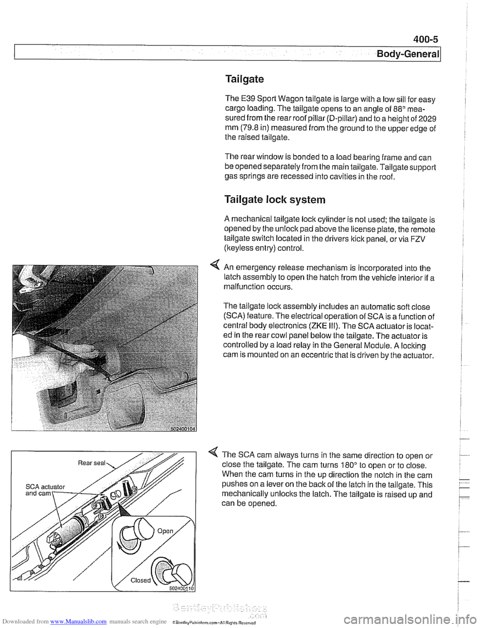
4 An emergency release mechanism is incorporated into the
latch assembly to open the hatch from the vehicle interior if a
malfunction occurs.
The tailgate lock assembly includes an automatic soft close
(SCA) feature. The electrical operation of SCA is a function of
central body electronics
(ZKE Ill). The SCA actuator is locat-
ed in the rear cowl panel below the tailgate. The actuator is
controlled by a load relay in the General Module. A locking
cam is mounted on an eccentric that is driven by the actuator.
4 The SCA cam always turns in the same direction to open or
close the tailgate. The cam turns
180" to open or to close.
When the cam turns in the up direction the notch in the cam
SCA actuator pushes on a lever on the back of the latch in the tailgate. This
mechanically unlocks the latch. The tailgate is raised up and
can be opened.
Page 805 of 1002
Downloaded from www.Manualslib.com manuals search engine
Instrument cluster
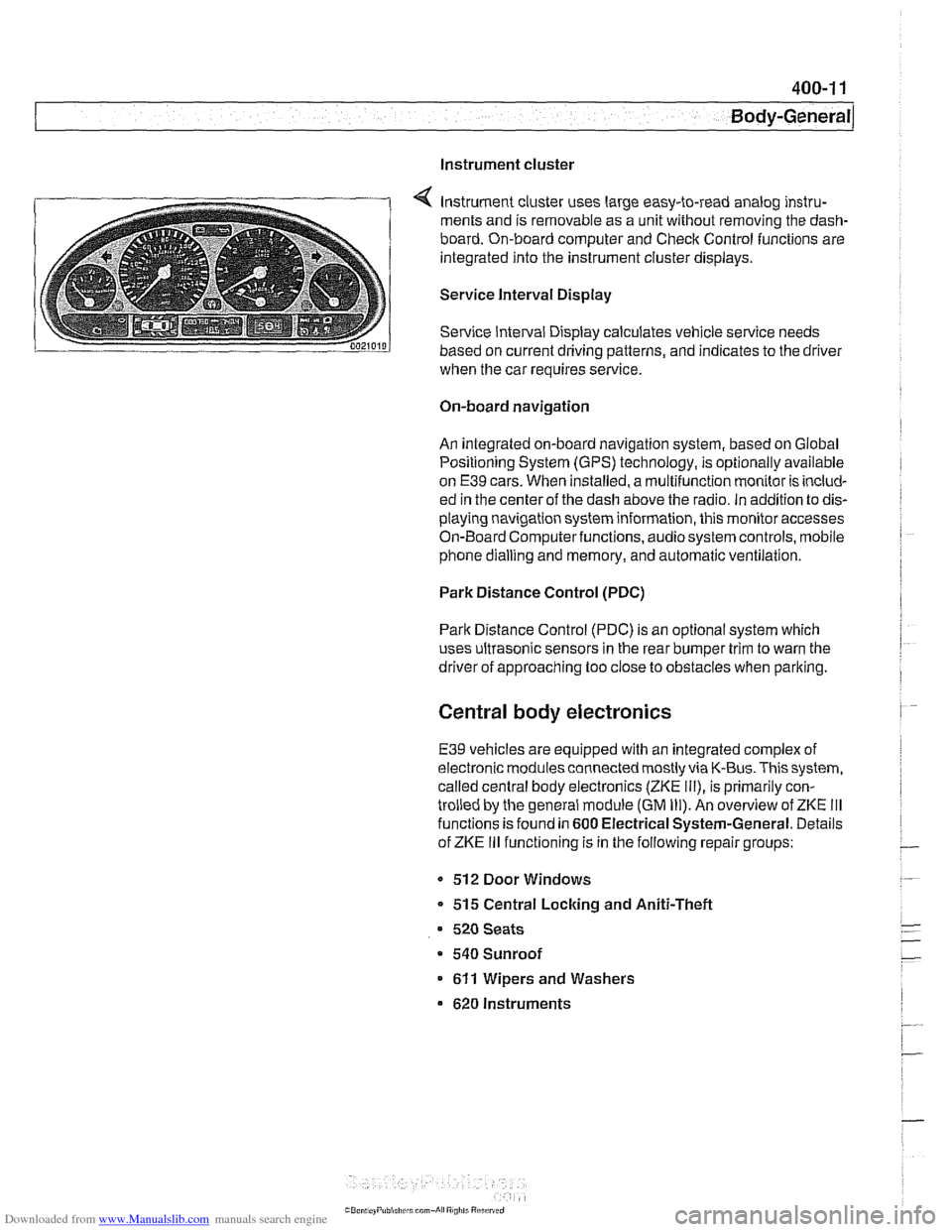
Instrument cluster uses large easy-to-read analog instru-
ments and is removable as a unit without removing the dash-
board. On-board computer and Check Control functions are
integrated into the instrument cluster displays.
Service Interval Display
Service Interval Display calculates vehicle service needs
based on current driving patterns, and indicates to the driver
when the car requires
service
On-board navigation
An integrated on-board navigation system, based on Global
Positioning System (GPS) technology, is optionally available
on
E39 cars. When installed, a multifunction monitor is includ-
ed in the center of the dash above the radio. in addition to dis-
playing navigation system information, this monitor accesses
On-Board Computerfunctions, audiosystem controls, mobile
phone dialling and memory, and automatic ventilation.
Park Distance Control (PDC)
Park Distance Control (PDC) is an optional system which
uses ultrasonic sensors in the rear bumper trim to warn the
driver of approaching too close to obstacles when parlting.
Central body electronics
E39 vehicles are equipped with an integrated complex of
electronic modules connected mostly via K-Bus. This system,
called central body electronics (ZKE
Ill), is primarily con-
trolled by the general module (GM
Ill). An overview of ZKE Ill
functions is found in 600 Electrical System-General. Details
of ZKE
Ill functioning is in the following repair groups:
- 512 Door Windows
* 515 Central Locking and Aniti-Theft
520 Seats
a 540 Sunroof
611 Wipers and Washers
620 Instruments
Page 809 of 1002
Downloaded from www.Manualslib.com manuals search engine
41 0-3
Fenders, Engine ~oodl
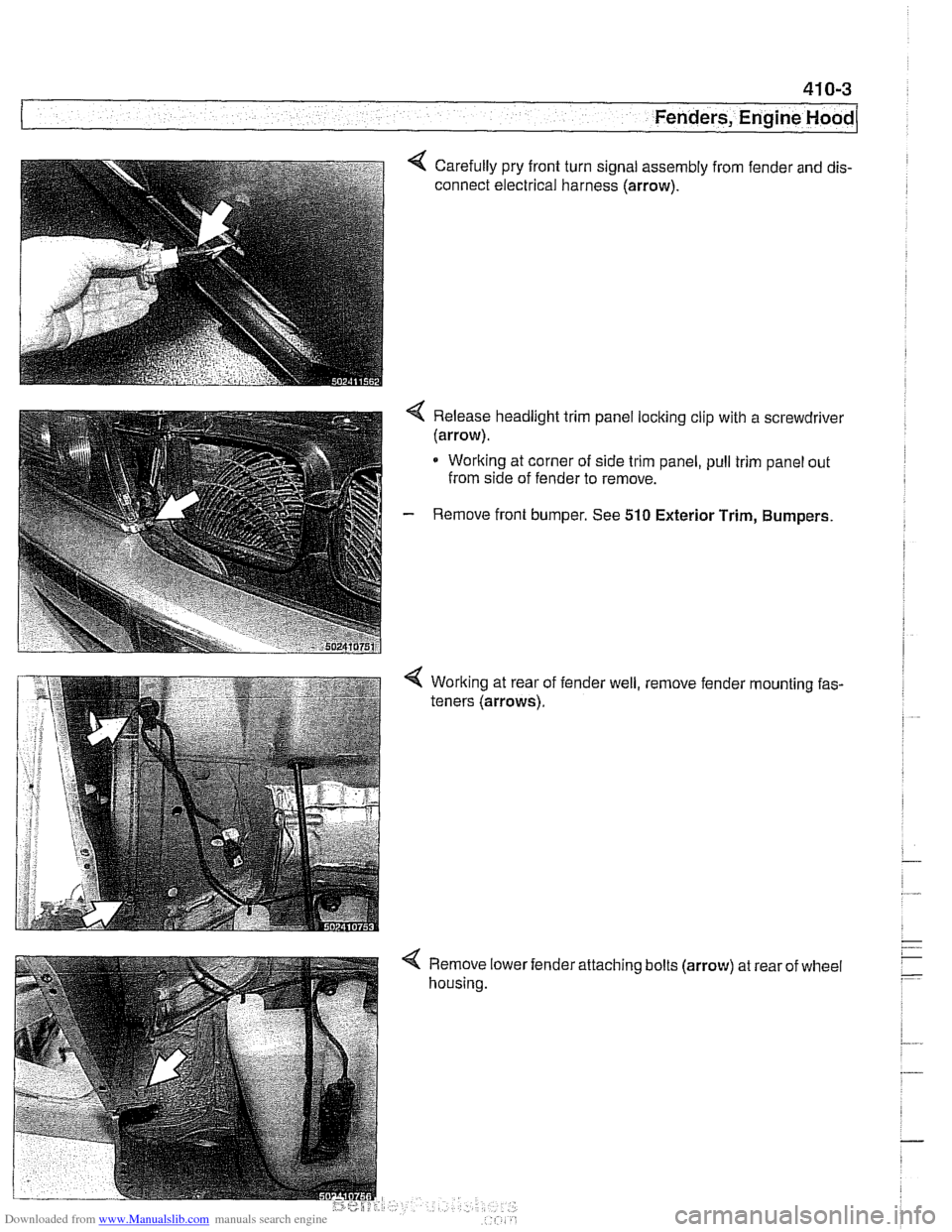
Carefully pry front turn signal assembly from fender and dis-
connect electrical harness (arrow).
< Release headlight trim panel locking clip with a screwdrivel
(arrow).
* Working at corner of side trim panel, pull trim panel out
from side of fender to remove.
- Remove front bumper. See 510 Exterior Trim, Bumpers.
Working at rear of
teners (arrows). fender
well, , remove
fender
'mounting fas-
< Remove lower
housing. 'attaching
bolts
(arrow) at rear of wheel
Page 820 of 1002
Downloaded from www.Manualslib.com manuals search engine
Doors
This repair group covers front and rear door repair informa-
tion. It includes removal and installation of front and rear
doors and trim panels.
For information on
airbag removal and installation, see 721
airbag.
For information on the power door windows and door glass
replacement, see
512 Door Windows.
For information on the power door
loclting system, see 515
Central Locking and Anti-Theft.
WARNING-
E39 cars are fitted with side-impact airbags in the front doors
and optional side impact
airbags in the rear doors. When
servicing doors, always disconnect the negative
(-) battery
terminal. See
721 Airbag System (SRS) for cautions and
procedures
relatinq to the airbaq system.
Front or rear door, removing and installing
- Disconnect negative (-) battery cable.
Prior to disconnecting the battery, read the battery discon-
nection cautionsgiven in
001 General Cautions and warn-
ings.
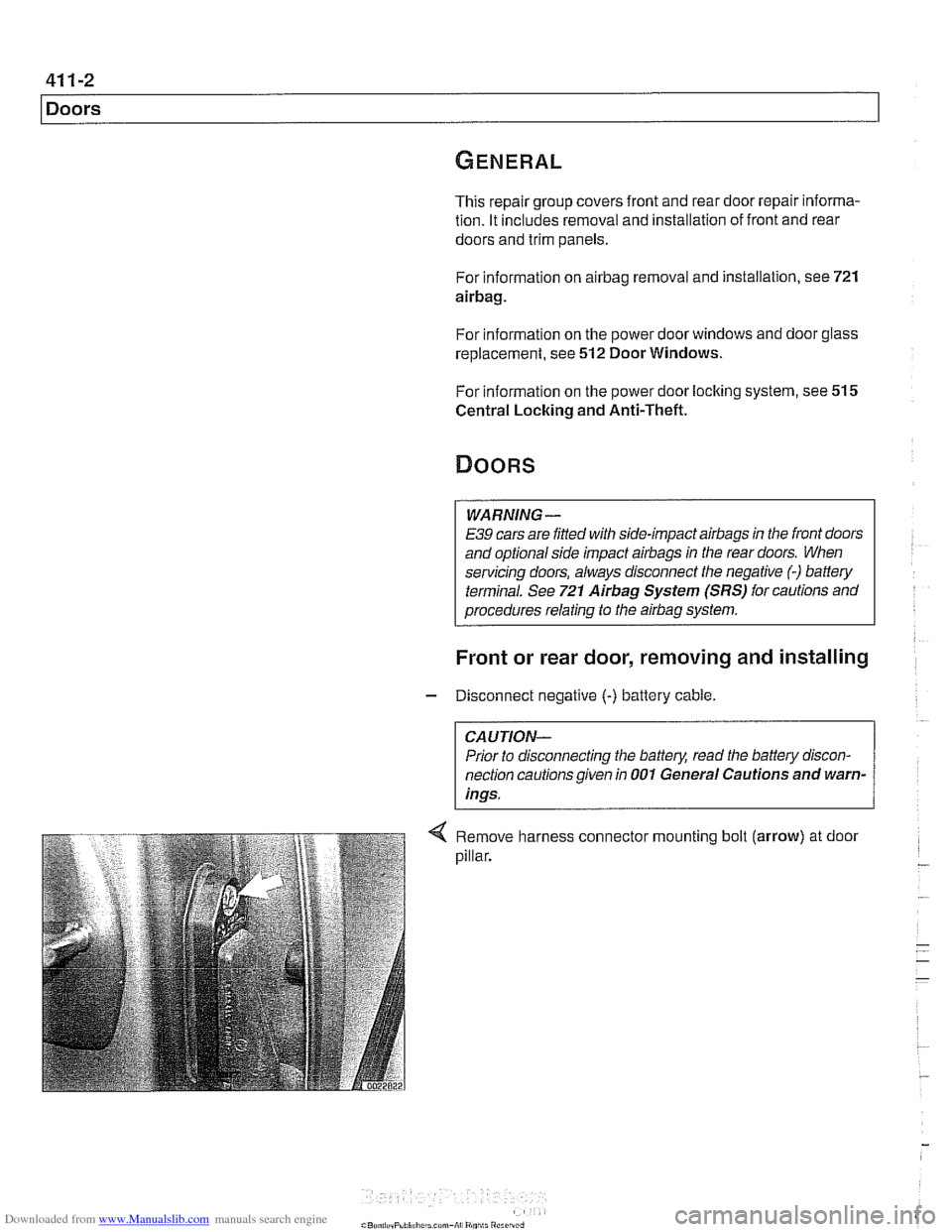
Remove harness connector mounting bolt (arrow) at door
pillar.
Page 821 of 1002
Downloaded from www.Manualslib.com manuals search engine
411-3
Doors
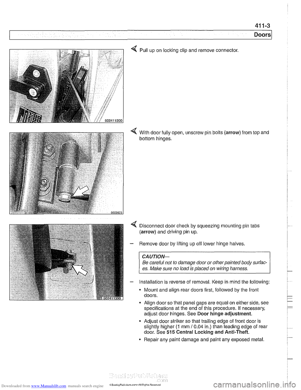
4 Pull up on locking clip and remove connector.
4 With door fully open, unscrew pin bolts (arrow) from top and
bottom hinges.
Disconnect door
check by squeezing mounting pin tabs
(arrow) and driving pin up.
Remove door by lifting up off lower hinge halves.
CAUJION-
Be careful not to damage door or otherpainted body surfac-
es.
Make sure no load is placed on wirinq harness.
Installation is reverse of removal. Keep in mind the following:
Mount and align rear doors first, followed by the front
doors.
Align door so that panel gaps are equal on either side, see
specifications at the end of this procedure. If necessary,
adjust door hinges. See Door hinge adjustment.
* Adjust door striker so that trailing edge of front door is
slightly higher
(I mm 10.04 in.) than leading edge of rear
door. See
515 Central Locking and Anti-Theft.
Repair any paint damage and paint any exposed metal.