Power steering fluid BMW 540i 1998 E39 User Guide
[x] Cancel search | Manufacturer: BMW, Model Year: 1998, Model line: 540i, Model: BMW 540i 1998 E39Pages: 1002
Page 675 of 1002
Downloaded from www.Manualslib.com manuals search engine
Steering and Wheel Alignment
Power assist is provided by a belt-driven pump at the lower
left front of the engine. The power steering fluid reservoir is lo-
cated at the left side of the engine compartment.
Power steering pump, removing and
installing
When working with power steering components, absolute
cleanliness is needed to ensure proper operation of the hy-
- Empty power steering fluid reservoir using clean syringe. Do
not reuse fluid.
- Raise front of car. Remove splash shield from under engine.
WARNING-
Make sure the car is firmly supported on jack stands de-
signed for the purpose. Place jack stands beneath structural
chassis points. Do not place jack stands under suspension
Darts.
Remove drive belt from power steering pump. See
020 Main-
tenance.
Remove alternator cooling duct
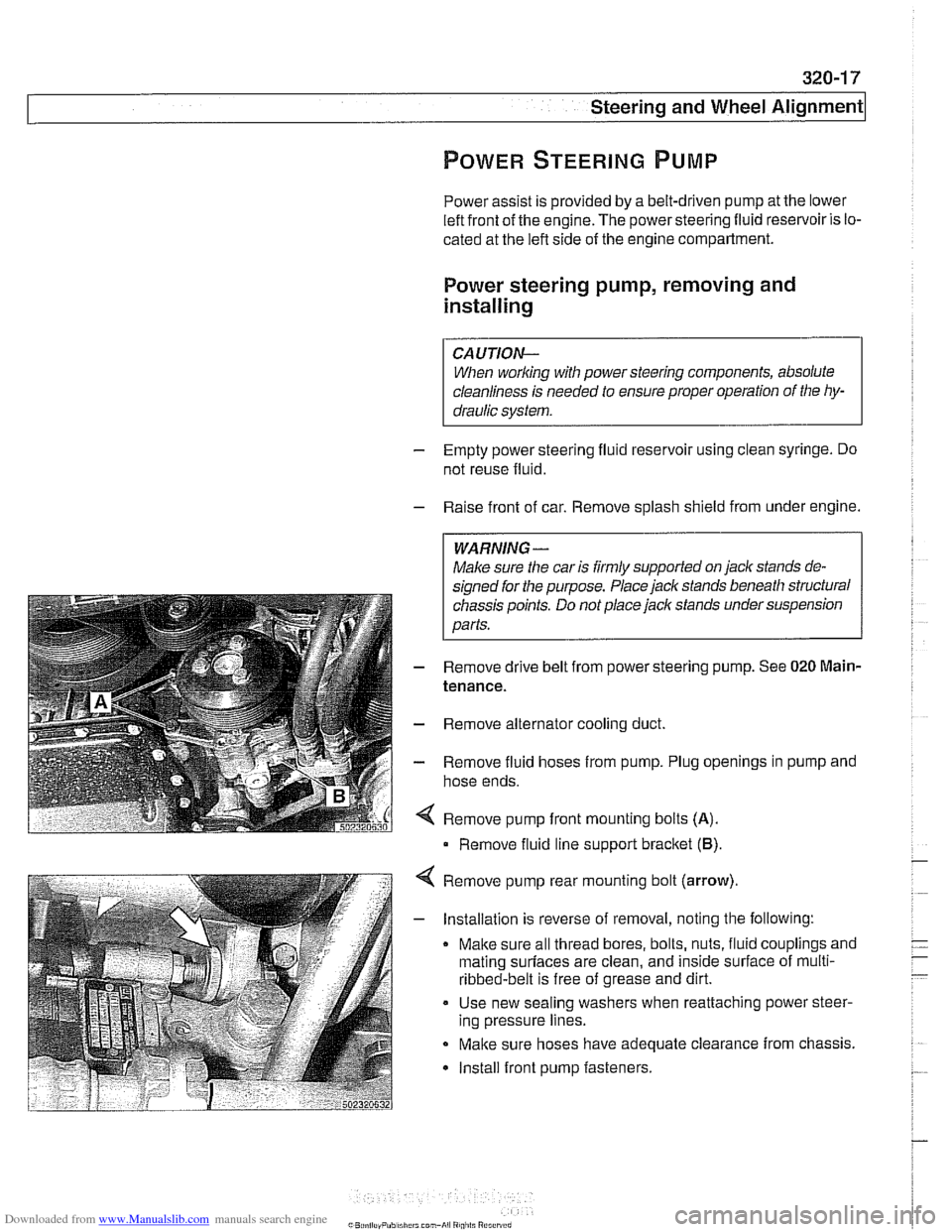
Remove fluid hoses from pump. Plug openings in pump and
hose ends.
Remove pump front mounting bolts
(A).
Remove fluid line support bracket (B)
Remove pump rear mounting bolt (arrow)
- Installation is reverse of removal, noting the following:
Make sure all thread bores, bolts, nuts, fluid couplings and
mating
surfaces are clean, and inside surface of multi-
ribbed-belt is free of grease and dirt.
Use new sealing washers when reattaching power steer-
ing pressure lines.
Make sure hoses have adequate clearance from chassis.
Install front pump fasteners.
Page 676 of 1002
Downloaded from www.Manualslib.com manuals search engine
-
-steering and wheel -. Alignment I
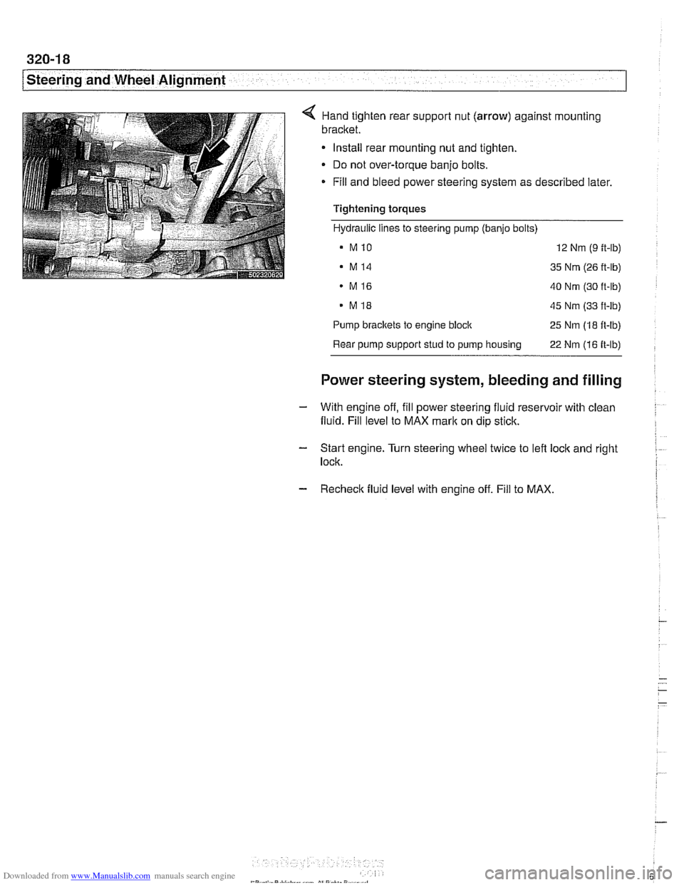
< Hand tighten rear suppoll nut (arrow) against mounting
bracket.
Install rear mounting nut and tighten.
Do not over-torque banjo bolts.
* Fill and bleed power steering system as described later.
Tightening torques
Hydraulic lines to steering pump (banjo bolts)
a MlO 12 Nm (9 ft-lb)
. M14 35 Nm (26 ft-lb)
MI6 40 Nm (30 ft-lb)
. MI8 45 Nm (33 ft-lb)
Pump
brackets to engine block 25 Nm (18 ft-lb)
Rear pump support stud to pump housing
22 Nm (16 ft-lb)
Power steering system, bleeding and filling
- With engine off, fill power steering fluid reservoir with clean
fluid. Fill level to MAX
mark on dip stick.
- Start engine. Turn steering wheel twice to left lock and right I
lock.
- Recheck fluid level with engine off. Fill to MAX.
Page 677 of 1002
Downloaded from www.Manualslib.com manuals search engine
i Steering and Wheel Alignment
RACK AND PINION STEERING
(6-CYLINDER MODELS)
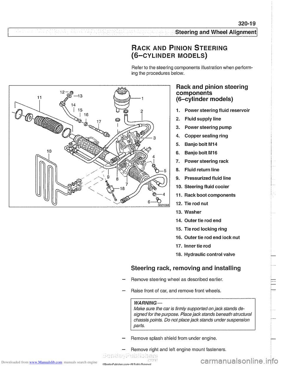
Refer to the steering components illustration when perform-
ing the procedures below.
Rack and pinion steering
components
(6-cylinder models)
1. Power steering fluid reservoir
2. Fluid supply line
3. Power steering pump
4. Copper sealing ring
5. Banjo bolt MI4
6. Banjo bolt MI6
7. Power steering rack
8. Fluid return line
9. Pressurized fluid line
10. Steering fluid cooler
11. Rack boot components
12. Tie rod nut
13. Washer
14. Outer tie rod end
15. Tie rod locking ring
16. Outer tie rod end loclc nut
17. Inner tie rod
18. Hydraulic control valve
Steering rack, removing and installing
- Remove steering wheel as described earlier.
- Raise front of car, and remove front wheels.
WARNING -
Male sure the car is firmly supported on jack stands de-
signed for the purpose. Place jack stands beneath structural
chassis points. Do
not place jack stands under suspension
parts.
- Remove splash shield from under engine.
- Remove right and lefl engine mount fasteners
-" ., - , . ,
Page 678 of 1002
Downloaded from www.Manualslib.com manuals search engine
/steering and Wheel Alignment
Raise engine approximately 40 mm (1.6 in). See 110 Engine
Removal and installation.
Remove right and left engine mounts and remove mount
brackets from subframe.
Empty power steering fluid reservoir using a clean syringe.
Do not reuse power steering fluid.
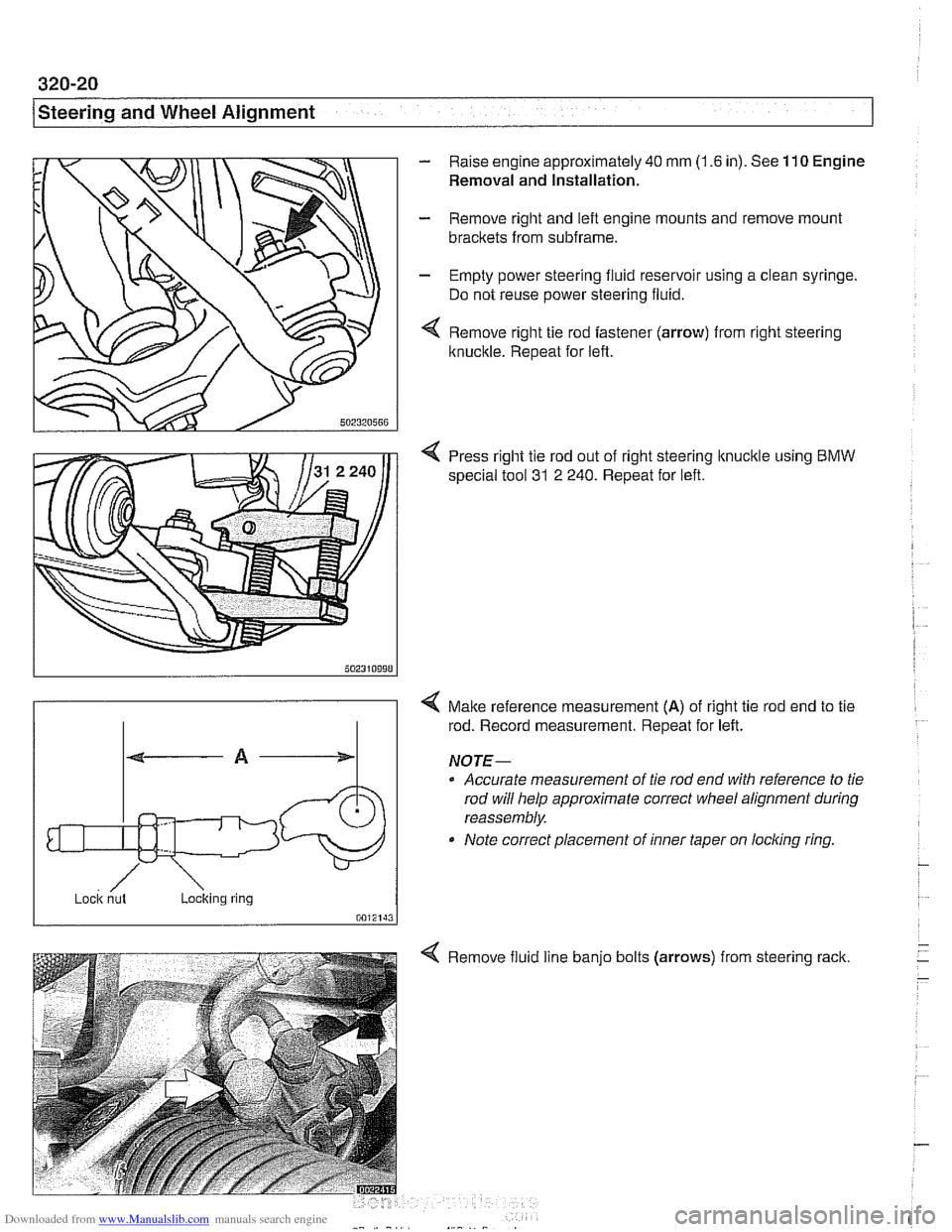
Remove right tie rod fastener (arrow) from right steering
Itnuckle. Repeat for left.
4 Press right tie rod out of right steering knucltle using BMW
special tool 31
2 240. Repeat for left.
/ ~ock nut Loclting ring
0012143
4 Malte reference measurement (A) of right tie rod end to tie
rod. Record measurement. Repeat for left.
NOJE-
0 Accurate measurement of tie rod end with reference to tie
rod will help approximate correct wheel alignment during
reassembly.
Note correct placement of inner taper on
locling ring
Remove fluid line
banjo bolts (arrows)
from steering rack.
Page 682 of 1002
Downloaded from www.Manualslib.com manuals search engine
Steering and Wheel Alignment
Tightening torques
Tie rod
to Steering knuckle (replace self-locking nut) 65 Nm (48 it-lb)
to Steering rack 71 Nrn (52 ft-lb)
Outer tie rod end lock nut 51 Nrn (38 ft-lb)
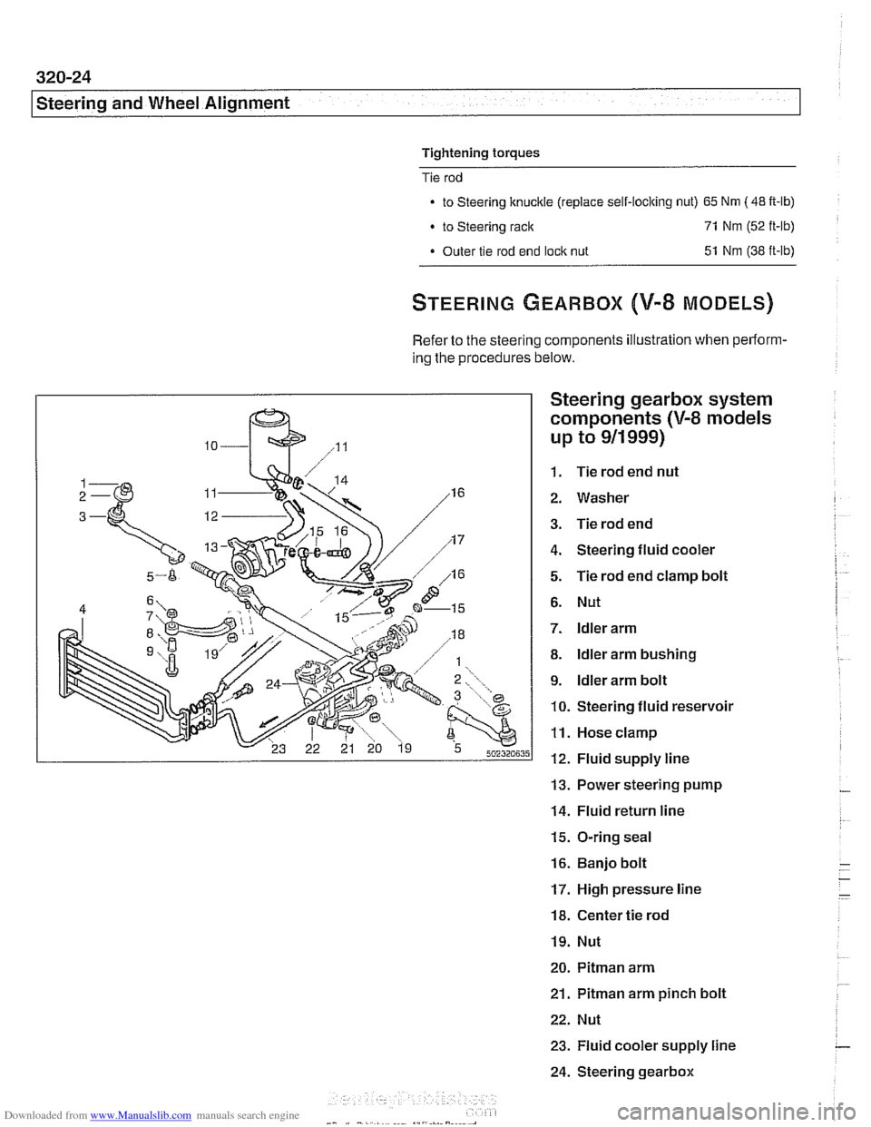
Refer to the steering components illustration when perform-
ing the procedures below.
Steering gearbox system
components
(V-8 models
up to
911 999)
1. Tie rod end nut
2. Washer
3. Tie rod end
4. Steering fluid cooler
5. Tie rod end clamp bolt
6. Nut
7. ldler arm
8. ldler arm bushing
9. ldler arm bolt
10. Steering fluid reservoir
11. Hose clamp
12. Fluid supply line
13. Power steering pump
14. Fluid return line
15. O-ring seal
16. Banjo bolt
17. High pressure line
18. Center tie rod
19. Nut
20. Pitman arm
21.
Pitman arm pinch bolt
22. Nut
23. Fluid cooler supply line
24. Steering gearbox
Page 683 of 1002
Downloaded from www.Manualslib.com manuals search engine
Steering and Wheel ~li~nrnentl
Steering gearbox, removing and installing
- Disconnect negative (-) battery cable. See 020 Mainte-
nance.
CAUTION-
Prior to disconnecting the battew read the battery discon-
nection cautions given in
001 General Cautions and
Warnings.
- Remove airbag unit from steering wheel. See 721 Airbag
System (SRS).
WARNING -
Improper handling of the airbag could cause serious injury
Store the
airbag with the horn pad facing up. If stored lacing
down, accidental deployment couldpropel it violently info the
air, causing
injuv
- Remove steering wheel as described earlier.
- Drain power steering system reservoir.
- Raise front of car.
WARNING -
Make sure the car is firmly supported on jack stands de-
signed for the purpose. Place jack stands beneath structural
chassis points. Do not place jack stands under suspension
Darts.
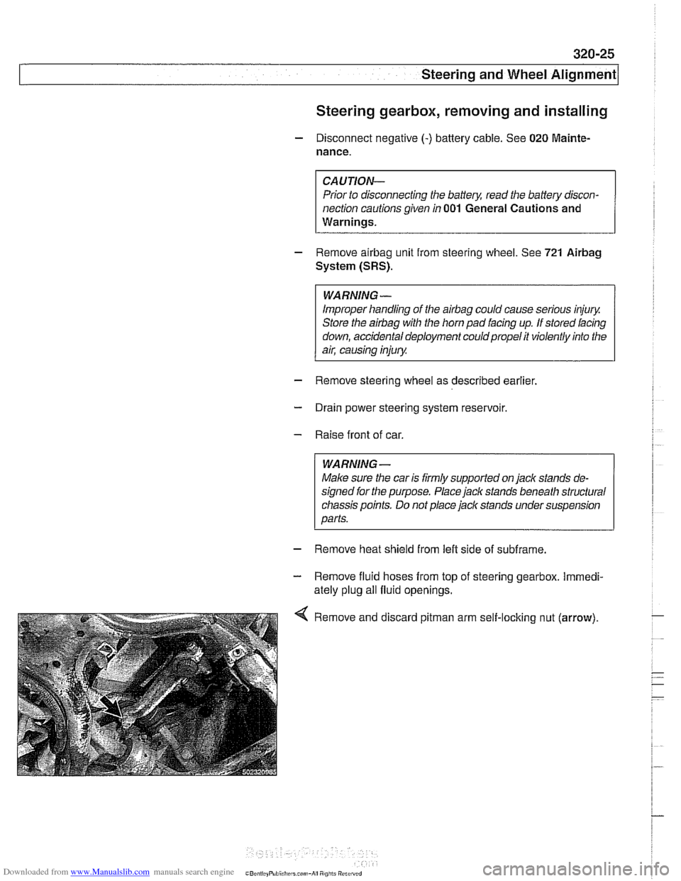
- Remove heat shield from left side of subframe.
- Remove fluid hoses from top of steering gearbox. Immedi-
ately plug all fluid openings.
Remove and discard
pitman arm self-loclting nut (arrow).
Page 685 of 1002
Downloaded from www.Manualslib.com manuals search engine
L.. Steering and Wheel ~li~nrnentl ~
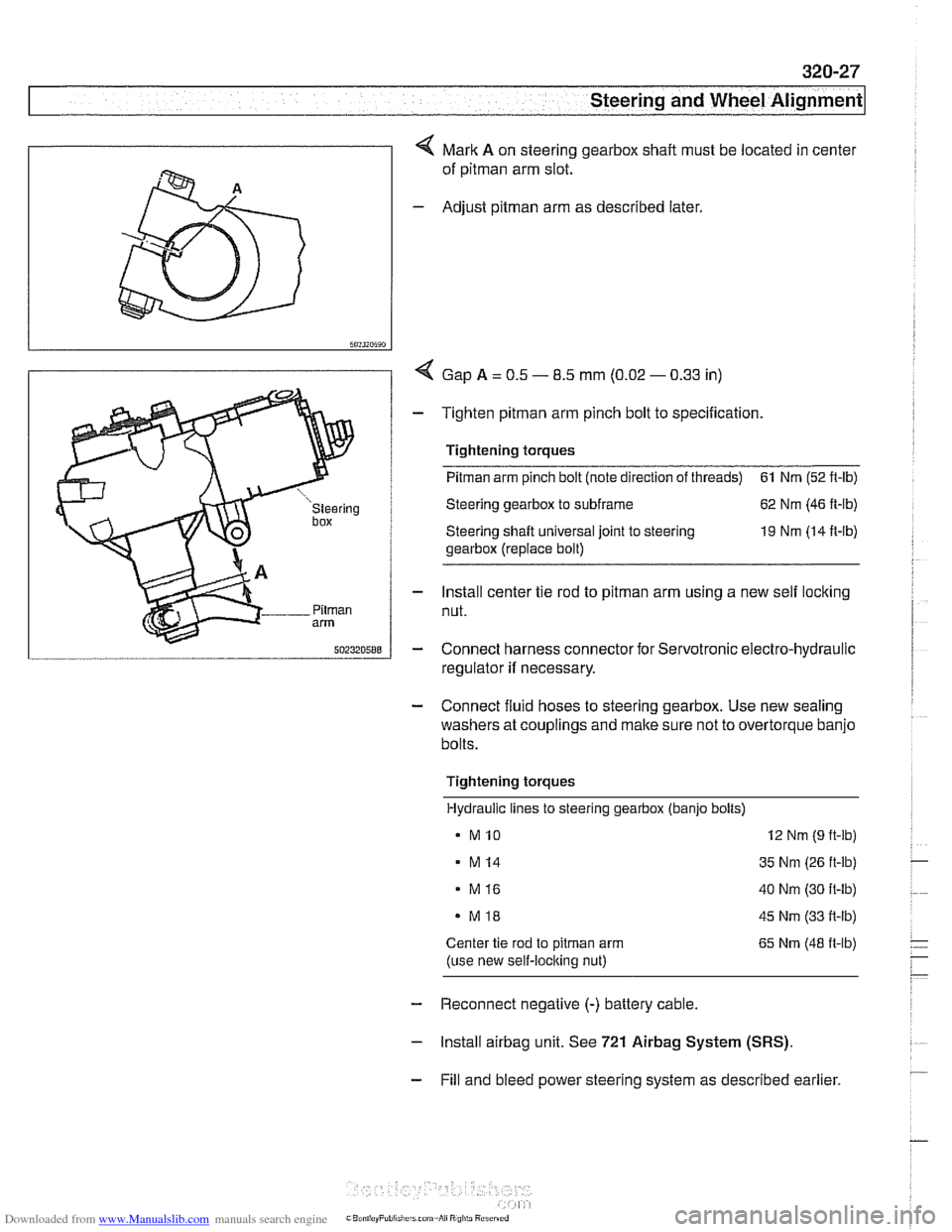
4 Mark A on steering gearbox shaft must be located in center
of
pitman arm slot.
- Adjust pitman arm as described later.
I 5"?~~5~"
I / < Gap A = 0.5 - 8.5 mm (0.02 - 0.33 in)
- Tighten pitman arm pinch bolt to specification.
' 1 Tightening torques
I u "steering Steering gearbox to subframe 62 Nm (46 ft-lb)
box Steering shaft universal joint to steering 19 Nm (14 It-lb)
gearbox (replace bolt)
- Install center tie rod to pitman arm using a new self locking
Pilrnan nut. arm
5nz3zn588 - Connect harness connector for Servotronic electro-hydraulic
regulator
if necessary.
- Connect fluid hoses to steering gearbox. Use new sealing
washers at couplings and make sure not to overtorque banjo
bolts.
Tightening torques Hydraulic lines to steering gearbox (banjo bolts)
MI0 12 Nm (9 ft-lb)
- M14 35 Nm (26 ft-lb)
. M16 40 Nm (30 ft-lb)
MI8 45 Nm (33 it-lb)
Center tie rod to pitrnan arm 65 Nm (48 it-lb)
(use new self-loclting nut)
- Reconnect negative (-) battery cable.
- lnstall airbag unit. See 721 Airbag System (SRS).
- Fill and bleed power steering system as described earlier.
Page 766 of 1002
Downloaded from www.Manualslib.com manuals search engine
E39 brake system
BMW E39 models are equipped with vacuum power-assisted
four-wheel disc brakes with an integral
Antilock Brake System
(ABS). Single-piston calipers act on vented front and rear ro-
tors. A brake pad wear sensor for each axle indicates when
brake pads need replacement. The dual drum-type parking
brake system is integrated with the rear brake rotors.
Electronic braking and stability control
E39 models were introduced with Automatic Stability Control,
a computer controlled traction control system that uses the
AB5 system in conjunction with engine management controls
to control wheel spin during take-off and maintain vehicle sta-
bility while braking.
Added in the
1998 model year was Dynamic Stability Control
(DSC). This system implements wheel speed modulation
throughout all stages of driving. For example, DSC is able to
reduce understeer by applying differing amounts of braking
force to each wheel, or it can override the engine manage-
ment system during hard cornering.
A summary of distinguishing characteristics of the various
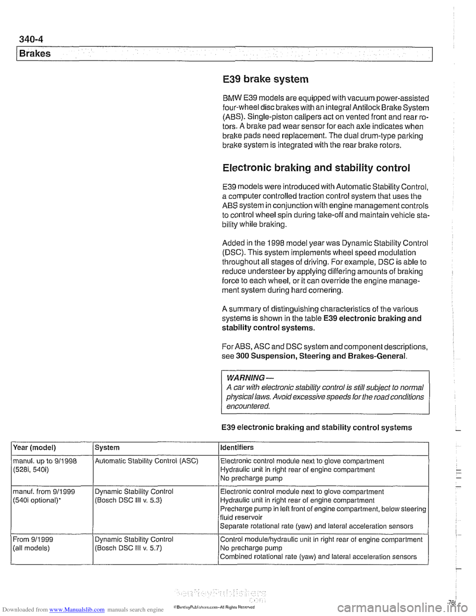
systems is shown in the table
E39 electronic braking and
stability control systems.
For ABS, ASC and DSC system and component descriptions,
see
300 Suspension, Steering and Brakes-General.
WARNING-
A car with electronic stability control is still subject to normal
physical laws. Avoid excessive speeds for the road conditions
encountered.
E39 electronic braking and stability control systems
Year (model)
manuf. up to 911998
(528i, 540i)
manuf. from 911999
(540i optional)*
From
911 999
(ail models) System
Automatic Stability Control (ASC) Identifiers
Electronic control module next to glove compartment
Hydraulic unit in right rear of engine compartment
No precharge pump
Dynamic Stability Control
(Bosch DSC
Ill v. 5.3)
Dynamic
Stabil~ty Control
(Bosch DSC
Ill v. 5.7) Electronic
control module next to glove compartment
Hydraulic unit in right rear of engine compartment
Precharge pump in left front of engine compartment, below steering
fluid reservoir
Separate rotational rate (yaw) and lateral acceleration sensors
Control
modulelhydraulic unit in right rear of engine compartment
No precharge pump
Combined rotational rate (yaw) and lateral acceleration sensors
Page 997 of 1002
Downloaded from www.Manualslib.com manuals search engine
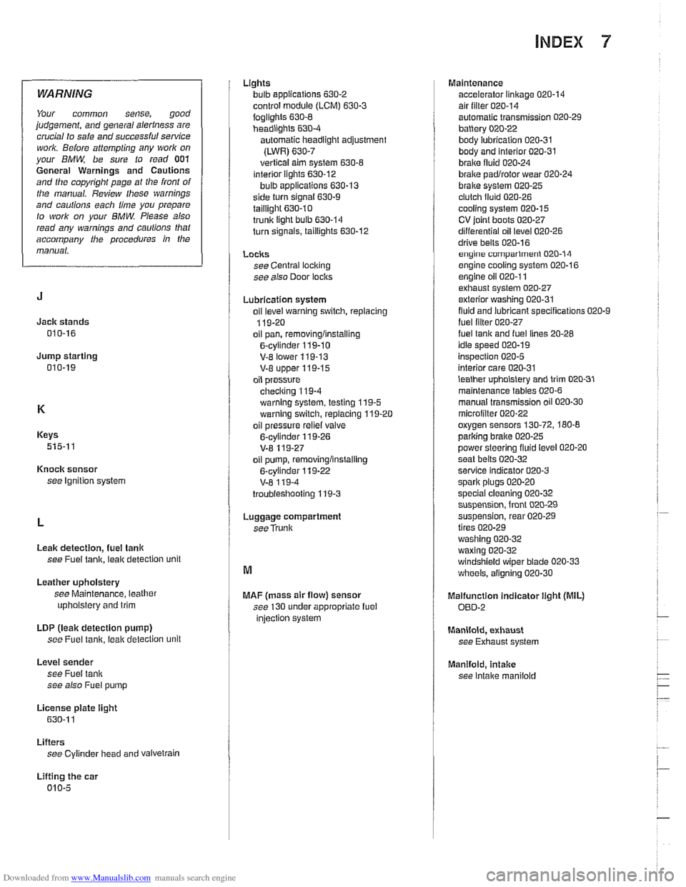
INDEX 7
WARNING
Your common sense, good
judgement, and general alertness are
crucial to safe and successful service
work. Before
attempting any work on
your BMW, be sure to read 001
General Warnings and Cautions
and the copyright page at the front of
the manual. Review these warnings
and cautions each time you prepare
to
work on your BMW. Please also
read any warnings and
caulions that
accompany
/he procedures in the
manual.
Jack stands
010-16
Jump starting 010-19
Keys
515-1 1
Knock sensor
see Ignition system
Leak detection,
fuel tanlr
see Fuel tank, leak detection unit
Leather upholstery
see Maintenance, leather
upholstery and trim
LDP
(leak detection pump)
see Fuel
tanir, leal( detection unit
Level sender
see Fuel tank
see also Fuel pump
License
plate iight
630-1 1
Lifters see Cylinder head and vaivetrain
Lifting the car
010-5 Lights
bulb applications
630-2
control module (LCM) 630-3
foglights 630-8 headiighls 630-4
automatic headlight adjustment
(LWR)
630-7
vertical aim system 630-8 interior lights 630-12
bulb applications 630-13
side turn signal 630-9
taillight 630.10 trunk light bulb 630-14
turn signals, taillights 630-12
LOClCS see Central loci(ing
see also Door loclrs
Lubrication system
oil
level warning switch, replacing
119-20
oil pan, removinglinstalling
6-cylinder 119-10
V-E lower 119-13 V-8 upper 119-15
oil pressure
checiring 11
9-4
warning system, testing 119-5 warning switch, replacing 119-20
oil pressure
reliel valve
6-cylinder 119-26
V-8 11 9-27
oil pump, removinglinstalling
6-cylinder
119-22
V-8 1 19-4
troubieshooting 119-3
Luggage compartment
seeTrunk
MAF (mass air flow) sensor
see 130 under appropriate fuel
injection system Maintenance
accelerator linkage
020-14 air filter 020-14
automatic transmission 020-29
battery 020-22
body lubrication 020-31 body and interior 020-31
braire fluid 020-24
brake padlrotor wear 020-24
brake system 020-25 clutch fluid 020-26
cooling system 020-15
CV ioint boots 020-27
differential oil level 020-26
drive bells 020-16 engine comparlmenl 020-14
engine cooling system 020-16
engine oil 020-1 1 exhaust system 020-27
exterior washing 020-31
fluid and lubricant specifications 020-9
fuel lilter 020-27 fuel lanir and fuel lines 20-28
idle speed 020-19
inspection 020-5
interior care 020-31
lealher upholslery and trim 020-31
maintenance tables 020-6
manual transmission oil 020-30
microiilter 020-22 oxygen sensors 130-72, 180-8
parlcing brake 020-25
power steering fluid level 020-20
seat belts
020-32 service indicator 020-3
spark plugs 020-20
special cleaning 020-32 suspension, front 020-29
suspension, rear 020-29
tires 020-29
washing
020-32
waxing 020-32 windshield wiper blade 020-33
wheels, aligning 020-30
Malfunction indicator iight (MIL)
OED-2
Manifold, exhaust
see Exhaust system
Manifold,
intake
see Intake maniiold
Page 998 of 1002
Downloaded from www.Manualslib.com manuals search engine
Manual transmission
applications 200-2. 230-5
back-up light switch, replacing 230-6
gear ratios 230-6
gearshift
see Gearshiit
ID tag 200-2
fluid 020-1 0. 200-4 fluid service 230-6
oil seals
input shaft seal, replacing
230-17
output shalt seal, replacing 230-1 1
selector
shaft seal, replacing 230-8 pilot bearing 210-16
removallinstallation 230-19
see also Maintenance
Map light
see Lights, interior
Mass air flow
(MAF) sensor
see 130 under appropriate fuel
injection syslem
Master cylinder
see Brakes
see also Clutch, hydraulics
MDK
130-42
Microfilter see
NC, ventilation microfilter
see also Maintenance
Mirror see Exterior trim
Misfire see Ignition syslem, diagnosis
Motor mount
see Engine,
mounl
MRS (multiple restraint system)
see Airbag system (SRS)
Muffler
see Exhaust syslem
Neutral safety switch
see Automatic transmission, range
switch
OED II (on-board diagnostics)
OED-l
Oil change equipment 010-16
Oil level sensor
see Lubrication system
Oil pan
see Lubrication system
OH pressure
see Lubrication system
Oil pump
see Lubrication system
Oil service 020-1 1
On-Board Monitor
640-12
On-board diagnostics OED-1
Outside air temperature sensor
610-14
Outside door handle
see Door
loclc
Outside mirror switch
see Switches
Output
shaft oil seal
see Manual transmission, oil seals
Overheating
see Cooling system, troubleshooting
Overload protection
600-11
Oxygen sensors
130-72, 180-8
P codes OED-10
Panic mode operation
515-11
Parking brake
see Brakes
see also Maintenance
Parts, buying
010-11
Pedal cluster switches
see Switches
Pedal position sensor (PWG)
6-cvlinder
enqine
V-8 engine (M62 TU) 130-68
Pitman arm
see Steering
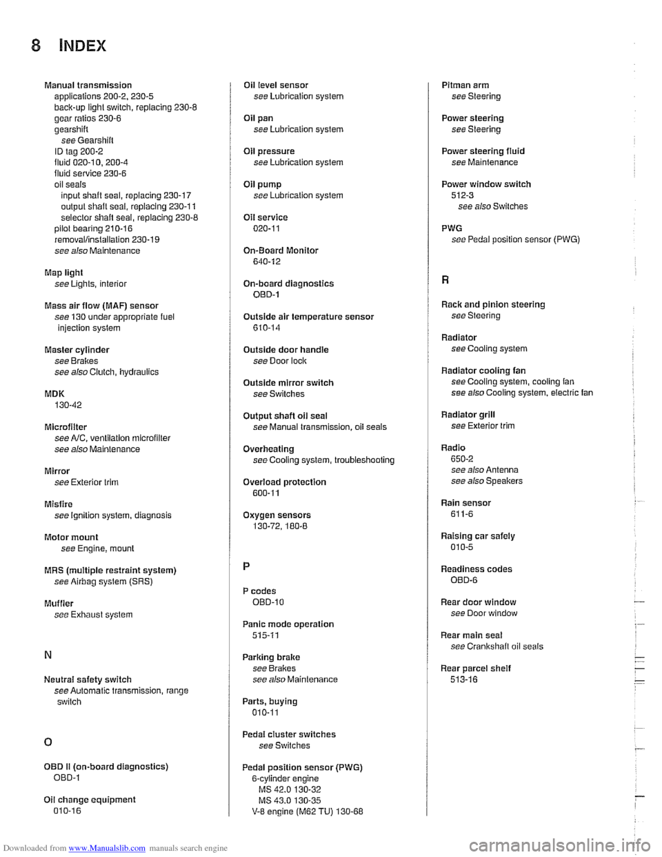
Power steering
see Steering
Power steering
fluid
see Maintenance
Power window switch
512-3 see also Switches
PWG see Pedal position sensor
(PWG)
Racic and pinion steering
see Steering
Radiator see Cooling system
Radiator cooling fan seeCooling system, cooling fan
see also Cooling system, electric fan
Radiator grill
see Exterior
trim
Radio
650-2 see also Antenna
see also Speakers
Rain sensor
611-6
Raising car safely
010-5
Readiness codes
OED-6
Rear door window
see Door window
Rear main seal
see Crankshalt oil seals
Rear parcel
sheif
513-16