differential BMW 540i 1998 E39 User Guide
[x] Cancel search | Manufacturer: BMW, Model Year: 1998, Model line: 540i, Model: BMW 540i 1998 E39Pages: 1002
Page 722 of 1002
Downloaded from www.Manualslib.com manuals search engine
330-26
/ Rear Suspension
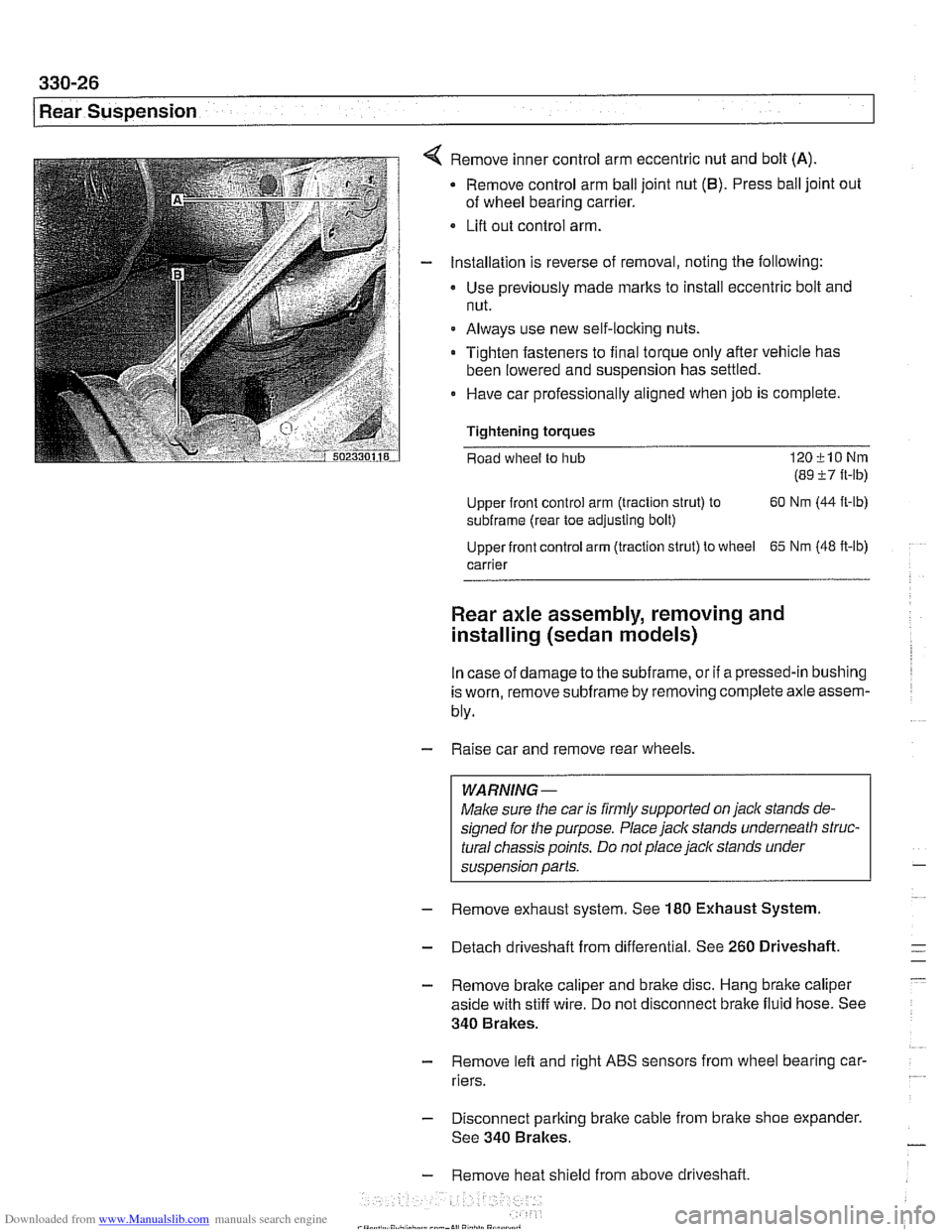
Remove inner control arm eccentric nut and bolt (A)
Remove control arm ball joint nut (6). Press ball joint out
of wheel bearing carrier.
Lifl out control arm.
Installation is reverse of removal, noting the following:
Use previously made
marks to install eccentric bolt and
nut.
Always use new self-locking nuts.
Tighten fasteners to final torque only after vehicle has
been lowered and suspension has settled.
0 Have car professionally aligned when job is complete.
Tightening
torques
Road wheel to hub 120klONm
(89 i7 ft-lb)
Upper front control arm (traction strut) to 60
Nm (44
ft-lb)
subframe (rear toe adjusting bolt)
Upper front control arm (traction strut) to wheel
65 Nm (48 ft-lb)
carrier
Rear axle assembly, removing and
installing (sedan models)
In case of damage to the subframe, or if a pressed-in bushing
is worn, remove
subframe by removing complete axle assem-
bly.
- Raise car and remove rear wheels.
WARNING-
Make sure the car is firmly supported on jack stands de-
signed for the purpose. Place jack stands underneath struc-
tural chassis points. Do not place
jack stands under
suspension parts.
- Remove exhaust system. See 180 Exhaust System
- Detach driveshaft from differential. See 260 Driveshaft.
- Remove brake caliper and brake disc. Hang brake caliper
aside with stiff wire. Do not disconnect brake fluid hose. See
340 Brakes.
- Remove lefl and right ABS sensors from wheel bearing car-
riers.
- Disconnect parking brake cable from brake shoe expander.
See 340 Brakes.
- Remove heat shield from above driveshaft.
Page 725 of 1002
Downloaded from www.Manualslib.com manuals search engine
Rear Suspension
- Remove exhaust system. See 180 Exhaust System.
- Detach driveshaft from differential. See 260 Driveshaft.
- Remove brake caliper and brake disc. Hang brake caliper
aside with stiff wire. Do not disconnect brake fluid hose. See
340 Brakes.
- Remove left and right ABS sensors from wheel bearing car-
riers.
Disconnect parking brake cable from brake shoe expander.
See 340 Brakes.
Remove heat shield from above driveshaft
If equipped, remove ride height sensor connectors
CAUTION-
Models with air springs: Disable air supply pump by discon-
necting electrical plug before performing any repairs. Pump is
locatedbeneath a coverunder
thespare tire in the floorof the
carqo compartment.
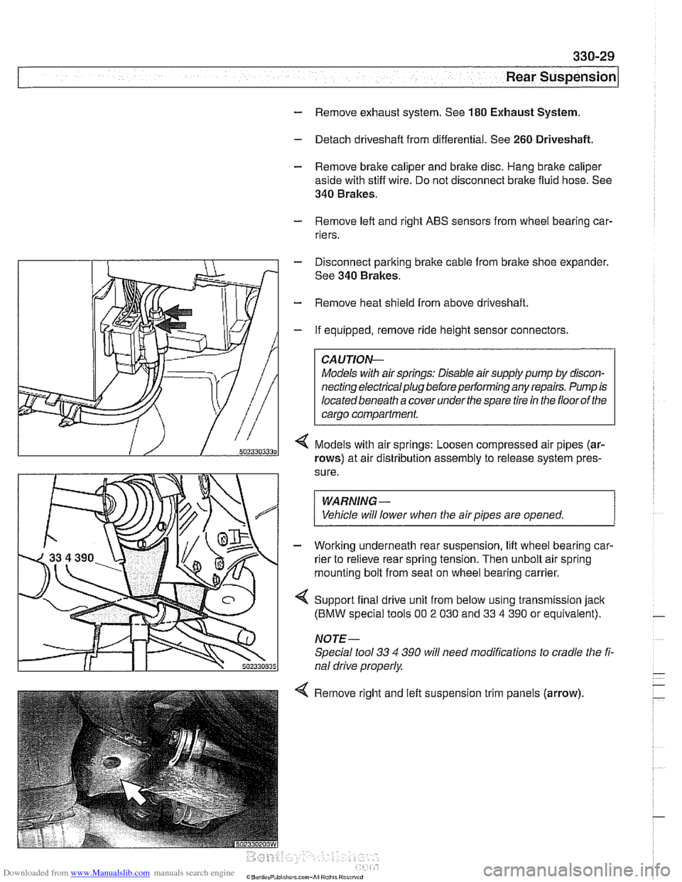
Models with air springs: Loosen compressed air pipes (ar-
rows) at air distribution assembly to release system pres-
sure.
WARNING -
Vehicle will lower when the air pipes are opened. 1
- Working underneath rear suspension, lift wheel bearing car-
rier to relieve rear spring tension. Then unbolt air spring
mounting bolt from seat on wheel bearing carrier.
4 Support final drive unit from below using transmission jack
(BMW special tools 00 2 030 and 33 4 390 or equivalent).
NOTE-
Special tool 33 4 390 will need modifications to cradle the fi-
nal drive properly
4 Remove right and left suspension trim panels (arrow),
Page 745 of 1002
Downloaded from www.Manualslib.com manuals search engine
33UFinal Drive
General ........................... ,331 -2 Drive Axles ....................... 331 -1 4
Special tools
........................ ,331 -2 Drive axle assembly ................. 331-14
Aluminum suspension components
...... ,331-4 Drive axle, removing and
installing (sedan)
.................... 331-14 ........................ Final Drive ,331 -5
Drive axle, removing
........... ...... Final drive, removing and installing ,331-5 and (Sport Wagon) 331-15
...................... Differential oil level, checking ........... ,331-6 CV joint boots 331-17 Final drive in~ut shaft seal, replacing ..... ,331-7 .
Final drive oitput shaft seals, replacing . . ,331-10
Final drive cover, removing and installing ,331-12
Final drive mounts, replacing .......... ,331-12
Page 746 of 1002
Downloaded from www.Manualslib.com manuals search engine
331-2
Final Drive
This repair group covers removal and repair informat~on for
the final drive (differential), axle shafts.
CV joints, CV joint
boots, and final drive seal replacement.
Internal repairs of the differential assembly are not covered in
this manual.
Special tools
BMW recommends some special tools for the removal of the
drive axles as well as the installation of rear differential input
and output drive flange seals. Some common pullers and
drifts can often be substituted for these tools.
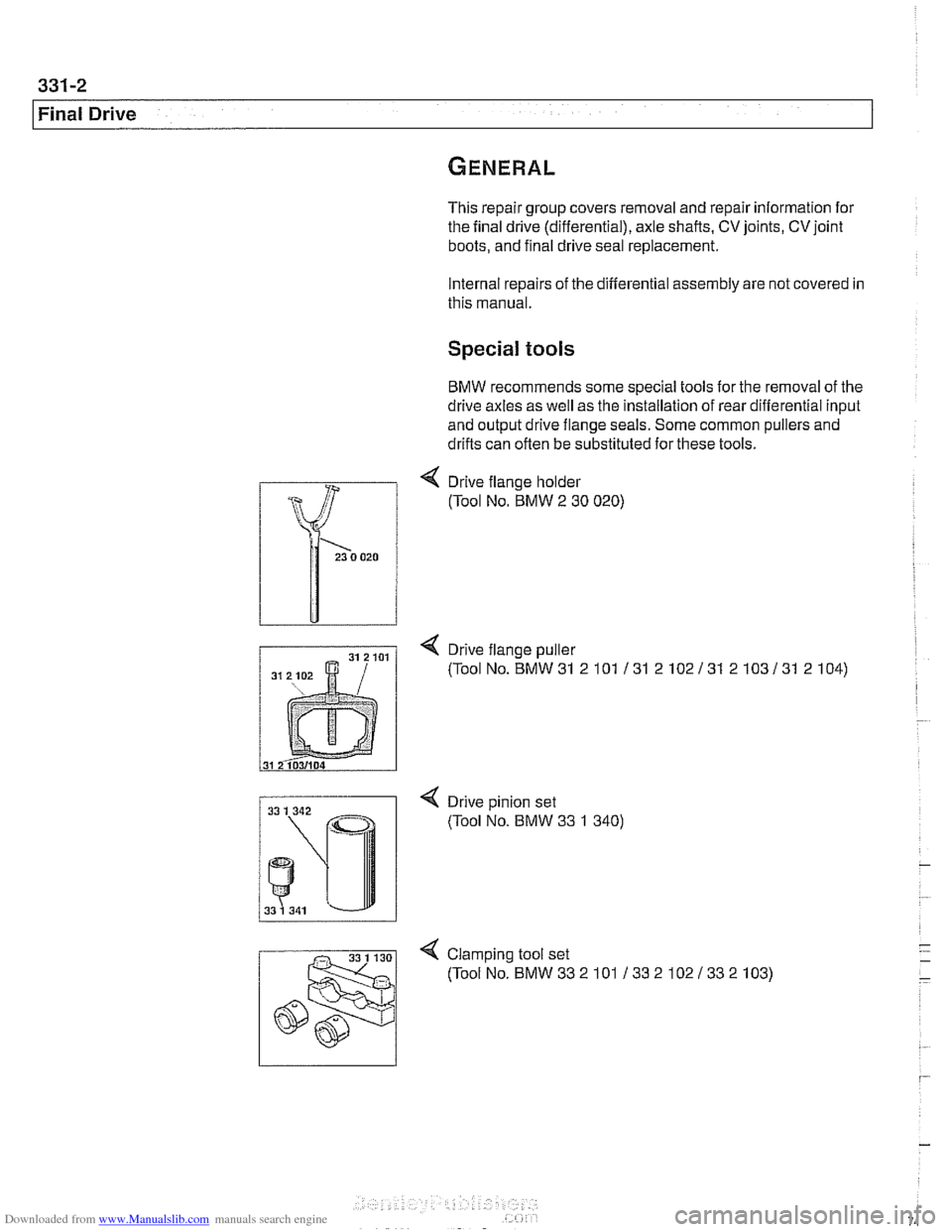
4 Drive flange holder
(Tool No. BMW
2 30 020)
< Drive flange puller
(ToolNo.BMW31 2101 131 2102131 2103131 2104)
< Drive pinion set
(Tool No. BMW 33 1 340)
4 Clamp~ng tool set
(ToolNo.BMW332101 13321021332103)
Page 747 of 1002
Downloaded from www.Manualslib.com manuals search engine
Final Drive
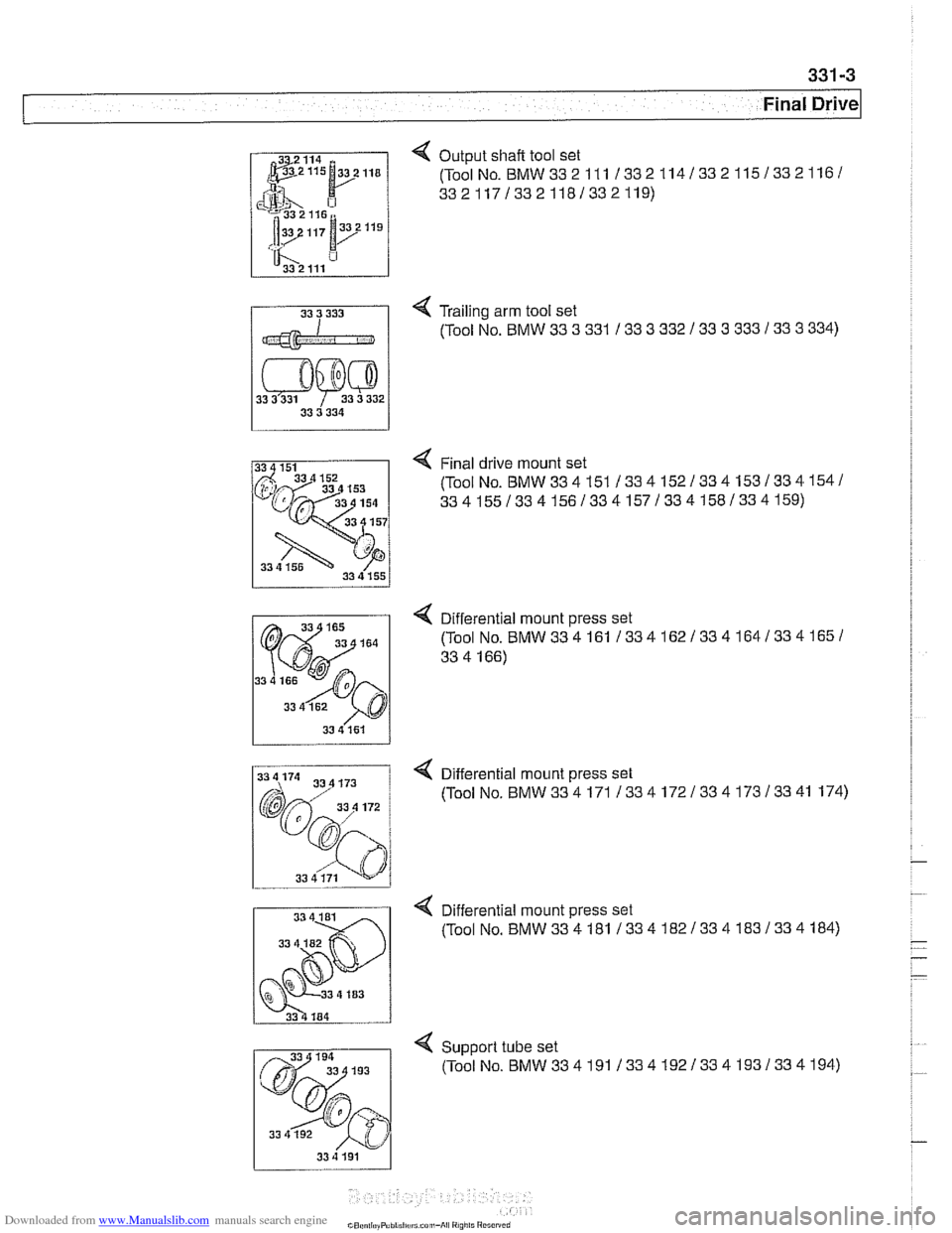
4 Output shaft tool set
(ToolNo.
BMW332111 1332114/332115/3321161
33211713321181332119)
4 Trailing arm tool set
11 (Tool NO BMW 33 3 331 I 33 3 332 1 33 3 333 133 3 334)
4 Final drive mount set
(ToolNo.
BMW334151 /334152/334153/334154/
3341551334156133415713341581334159)
< Differential mount press set
(Tool
No.BMW334161 1334162133416413341651
33 4 166)
33 4 161
Q Differential mount press set
(ToolNo.
BMW334171 /334172/334173/3341 174)
. .
33 4 181 4 Differential mount press set
33 (Tool No. BMW334181 133418213341831334184)
Support tube set
(ToolNo.BMW334191133419213341931334194)
33 4 192
33 4 191
Page 749 of 1002
Downloaded from www.Manualslib.com manuals search engine
Final Drive
Final drive, removing and installing
- Raise rear of car.
WARNING-
Make sure that the car is firmly supported on jack stands de-
signed for the purpose. Place the jaclc stands beneath struc-
tural chassis
~oints. Do not i lace iaclc stands under
( suspension barfs.
Remove exhaust system. See 180 Exhaust System.
Disconnect drive shaft from final drive. See
260 Driveshaft.
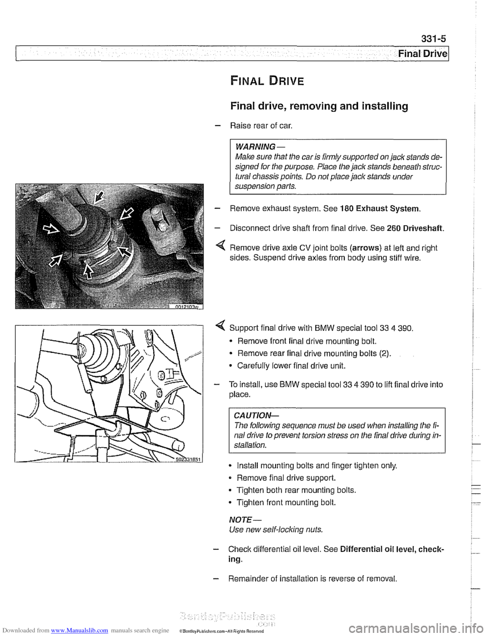
Remove drive axle CV joint bolts (arrows) at left and right
sides. Suspend drive axles from body using stiff wire.
4 Support final drive with BMW special tool 33 4 390.
* Remove front final drive mounting bolt.
Remove rear final drive mounting bolts
(2).
Carefully lower final drive unit.
- To install, use BMW special tool 33 4 390 to lift final drive into
place.
CA UTIOP&
The following sequence must be used when installing the fi-
nal drive to prevent torsion stress on the final drive during in-
Install mounting bolts and finger tighten only.
Remove final drive support.
Tighten both rear mounting bolts.
Tighten front mounting bolt.
NOTE-
Use new self-locking nuts.
- Check differential oil level. See Differential oil level, check-
ing.
- Remainder of installation is reverse of removal.
Page 750 of 1002
Downloaded from www.Manualslib.com manuals search engine
Final Drive
Tightening torques
F~nal drive to rear axle carrier 105 Nm (77 it-lb)
Driveshaft CV joint to final drive flange
- MlO (Torx bolt) 70
Nm (51 ft-lb)
- M8 (compression nut) 32 Nm (24
ft-lb)
Drive axle to final drive
ilange
Torx bolts (M10) 83 Nm (61 ft-lb)
Torx bolt with
rlbbed teeth (M10) 64 Nm (47 ft-lb)
Torx bolt
wlth ribbed teeth (MI0 sliver) 80 Nm (59 ft-lb)
Torx
bolt with ribbed teeth (M10 black) 100 Nm (74 ft-lb)
* Torx bolt with ribbed teeth (M12) 135 Nm (100 ft-lb)
Differential oil level, checking
The E39 differential is filled with lifetime oil that ordinarily
does not need to be changed. BMW recommends using only
a specially formulated synthetic gear oil
(SAF-XO) that is
available through an authorized BMW dealer parts depart-
ment. For additional information on this lubricant and any oth-
er lubricants that may be compatible, contact an authorized
BMW dealer service department.
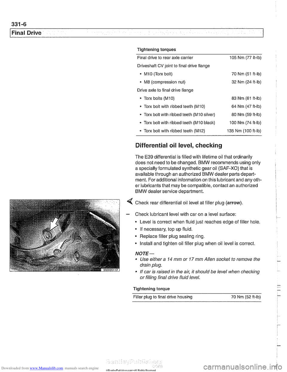
< Check rear differential oil level at filler plug (arrow).
- Check lubricant level with car on a level surface:
Level is correct when fluid just reaches edge of filler hole.
If necessary, top up fluid.
* Replace filler plug sealing ring.
Install and tighten oil filler plug when oil level is correct.
NOTE-
Use either a 14 mm or 17 mm Allen socket to remove the
drain plug.
If car is raised in the air. it should be level when
checkino " or filling final drive fluid level.
- Tightening torque -
Filler plug to final drive housing 70 Nm (52
ft-lb) -
Page 753 of 1002
Downloaded from www.Manualslib.com manuals search engine
331-9
Final Drive
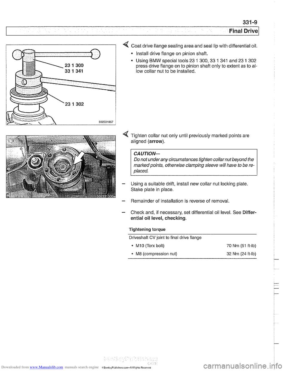
Coat drive flange sealing area and seal lip with differential oil.
* Install drive flange on pinion shaft.
Using
BMW special tools 23 1 300,33 1 341 and 23 1 302
press drive flange on to pinion shaft only to extent as to al-
low collar nut to be installed.
4 Tighten collar nut only until previously marked points are
aligned (arrow).
CAUTION-
Do not underany circumstances tighten collarnut beyond the
markedpoints,
othe~lise clamping sleeve will have to be re-
placed.
- Using a suitable drift, install new collar nut locking plate
Stalte plate in place.
- Remainder of installation is reverse of removal.
- Check and, if necessary, set differential oil level. See Differ-
ential oil level, checking.
Tightening torque Driveshaft
CV joint to final drive flange
MI0 (Torx bolt) 70 Nrn (51 ft-lb)
ME (compression nut) 32 Nrn (24 ft-lb)
Page 755 of 1002
Downloaded from www.Manualslib.com manuals search engine
331-1 1
Final rive(
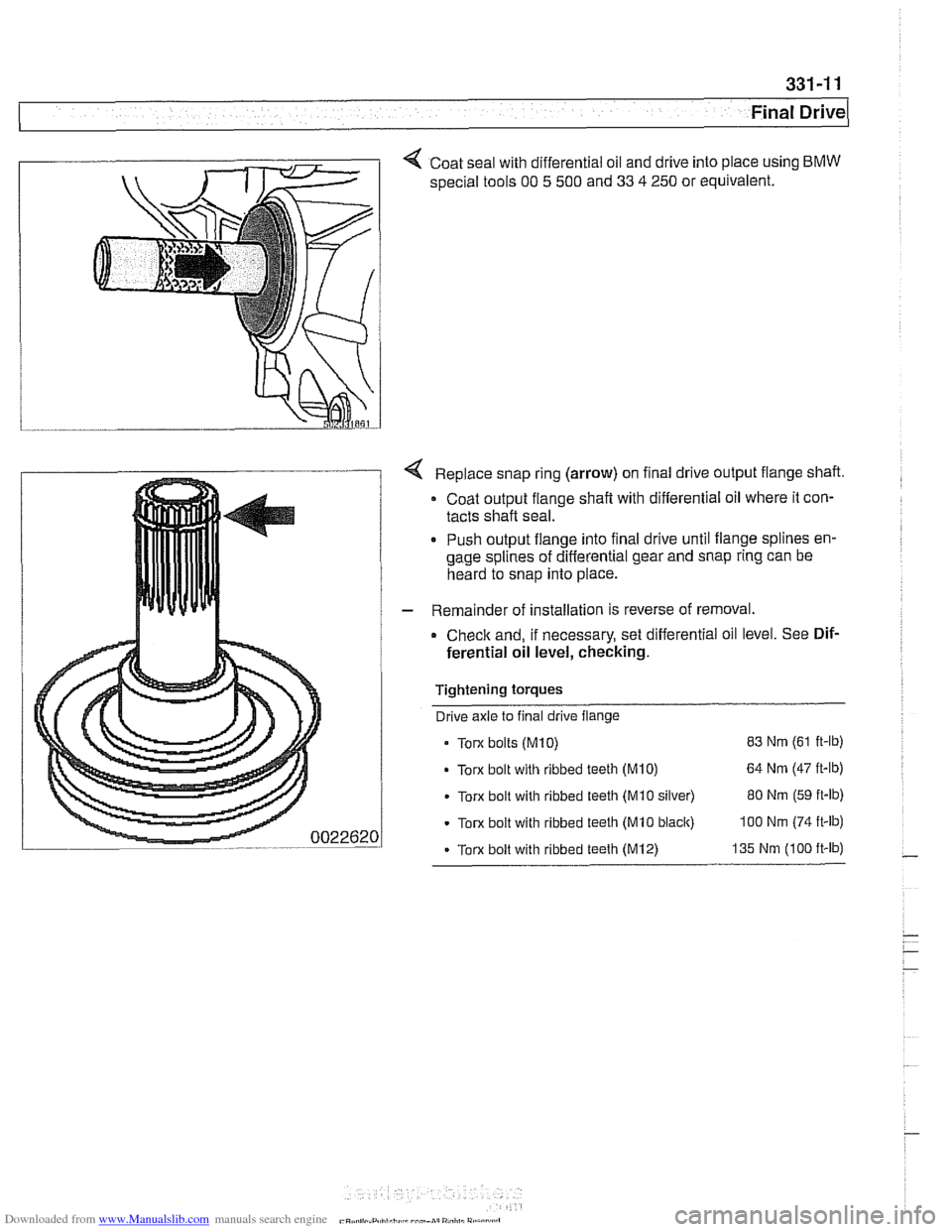
< Coat seal with differential oil and drive into place using BMW
special tools 00 5 500 and 33 4 250 or equivalent.
Replace snap ring (arrow) on final drive output flange shaft.
Coat output flange
shaft with differential oil where it con-
tacts shaft seal.
. Push output flange into final drive until flange splines en-
gage splines of differential gear and snap ring can be
heard to snap into place.
- Remainder of installation is reverse of removal.
Check and, if necessary, set differential oil level. See Dif-
ferential oil level, checking.
Tightening torques Drive axle to final drive flange
Torx bolts
(M10) 83 Nm (61 ft-lb)
Torx bolt with ribbed teeth (M10) 64 Nm (47 it-lb)
Torx bolt with ribbed teeth (Mi0 silver) 80 Nm (59 ft-lb)
Torx bolt with ribbed teeth (MI0 black) 100 Nm (74 ft-lb)
- Torx bolt with ribbed teeth (M12) 135 Nm (100 ft-lb)
Page 756 of 1002
Downloaded from www.Manualslib.com manuals search engine
331-12
Final Drive Final drive cover, removing and installing
- Remove final drive. See Final drive, removing and install-
ing.
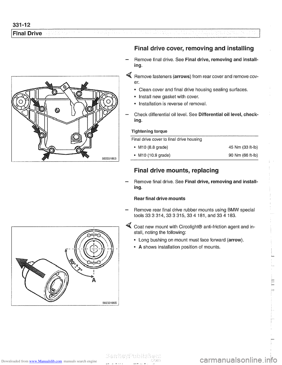
I 1 4 Remove fasteners (arrows) from rear cover and remove cov-
er.
Clean cover and final drive housing sealing surfaces.
Install new
gasket with cover.
* Installation is reverse of removal.
- Check differential oil level. See Differential oil level, check-
ing.
Tightening
torque
Final drive cover to final drive housing
. M10 (8.8 grade) 45 Nm (33 ft-lb)
M10 (10.9 grade) 90 Nm (66 ft-lb)
Final drive mounts, replacing
- Remove final drive. See Final drive, removing and install-
ing.
Rear final drive mounts
- Remove rear final drive rubber mounts using BMW special
tools333314,333315,334 181, and334 183.
4 Coat new mount with CircolightB anti-friction agent and in-
.
stall, noting the following:
Long bushing on mount must face forward (arrow).
A shows installation position of mounts.