differential BMW 540i 1998 E39 Owner's Manual
[x] Cancel search | Manufacturer: BMW, Model Year: 1998, Model line: 540i, Model: BMW 540i 1998 E39Pages: 1002
Page 759 of 1002
Downloaded from www.Manualslib.com manuals search engine
Final ~rivel
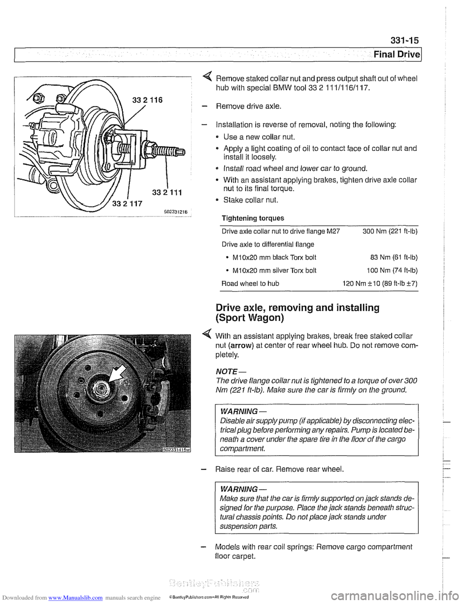
4 Remove staked collar nut and press output shafl out of wheel
hub with special
BMW tool 33 2 111/116/117.
- Remove drive axle.
- Installation is reverse of removal, noting the following:
Use a new collar nut.
a Apply a light coating of oil to contact face of collar nut and
install it loosely.
* Install road wheel and lower car to ground.
- With an assistant applying brakes, tighten drive axle collar
nut to its final torque.
Stake collar nut.
Tightening torques
-
Drive axle collar nut to drive flange M27 300 Nrn (221 ft-lb)
Drive axle to differential flange
* M10x20 rnm black Torx bolt
83 Nrn (61 ft-lb)
M10x20 rnrn silver Torx bolt
100 Nrn (74 ft-lb)
Road wheel to hub 120 Nrn f 10 (89 ft-lbf7)
Drive axle, removing and installing
(Sport Wagon)
4 With an assistant applying brakes, brealc free staked collar
nut (arrow) at center of rear wheel hub. Do not remove com-
pletely.
NOJE-
The drive flange collar nut is tightened to a torque of over 300
Nm (221 ft-lb). Make sure the car is firmly on the ground.
WARNING -
Disable airsupply pump (if applicable) by disconnecting elec-
tricalplug before performing any repairs. Pump is located be-
neath a cover under the spare tire
in the floor of the cargo
compartment.
- Raise rear of car. Remove rear wheel.
WARNING -
Malce sure that the car is firmly supported on jack stands de-
signed for the purpose. Place the jack stands beneath struc-
tural chassis points. Do not place jack stands under
suspension parts.
- Models with rear coil springs: Remove cargo compartment
floor carpet.
Page 761 of 1002
Downloaded from www.Manualslib.com manuals search engine
331-17
Final ~rivel
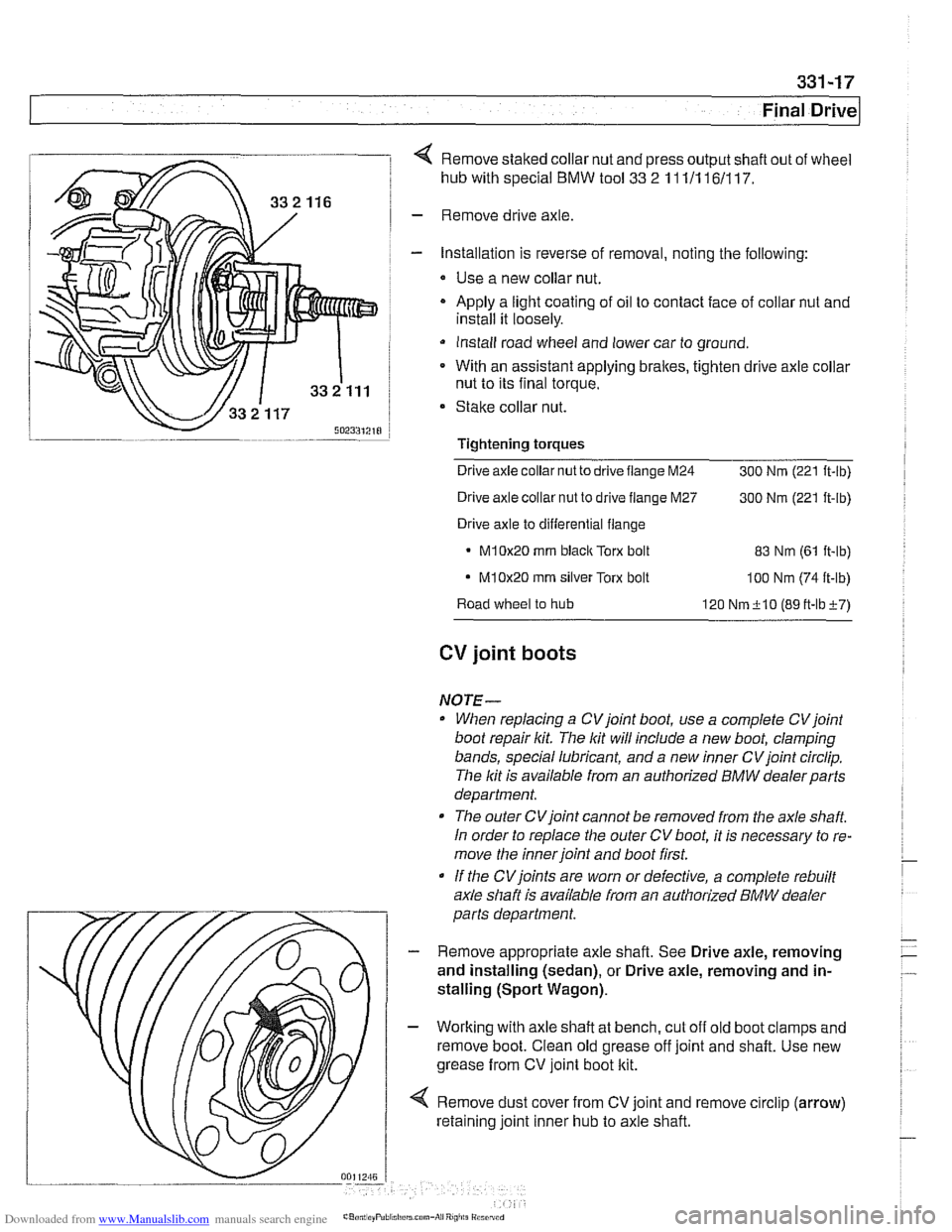
4 Remove staked collar nut and press output shaft out of wheel
hub with special
BMW tool 33 2 11 111 161117.
- Remove drive axle
- Installation is reverse of removal, noting the following:
* Use a new collar nut.
- Apply a light coating of oil to contact face of collar nut and
install it loosely.
Install road wheel and lower car to ground.
* With an assistant applying brakes, tighten drive axle collar
nut to its final torque.
Stake collar nut.
Tightening
torques
Drive axle collar nut to drive flange M24
300 Nrn (221 ft-lb)
Drive axle collar nut to drive flange M27
300 Nrn (221 ft-lb)
Drive axle to differential flange
M10x20 rnrn blaclc Torx bolt 83 Nrn (61 it-lb)
- M10x20 rnrn silver Torx bolt loo Nrn (74 ft-lb)
Road wheel to hub
120 Nrn+lO (89tt-lbi-7)
CV joint boots
NOTE-
When replacing a CVjoint boot, use a complete CVjoint
boot repair kit. The lit will include a new boot, clamping
bands, special lubricant, and a new inner CV joint circlip.
The lit is available from an authorized
BMW dealerparts
department.
The outer CVjoint cannot be removed from the axle
shaft
In order to replace the outer CV boot, it is necessary to re-
move the inner joint and boot first.
If the
CVjoints are worn or defective, a complete rebuilt
axle shaft is available from an authorized
BMW dealer
parts department.
- Remove appropriate axle shaft. See Drive axle, removing
and installing (sedan), or Drive axle, removing and in-
stalling (Sport Wagon).
- Working with axle shaft at bench, cut off old boot clamps and
remove boot. Clean old grease off joint and shaft. Use new
grease from CV joint boot kit.
4 Remove dust cover from CV joint and remove circlip (arrow)
retaining joint inner hub to axle shaft.
Page 762 of 1002
Downloaded from www.Manualslib.com manuals search engine
I Final Drive
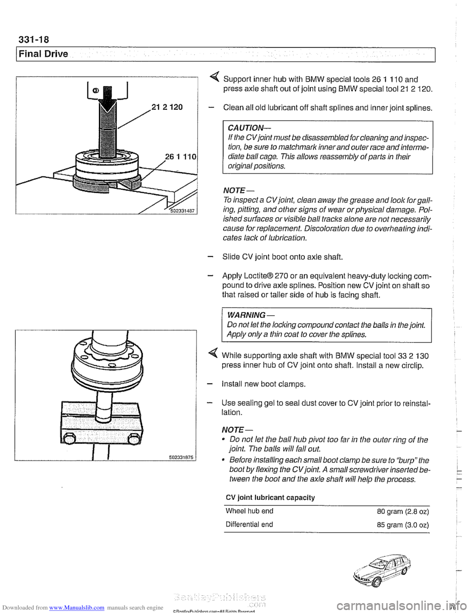
4 Support inner hub with BMW special tools 26 1 110 and
press axle shaft out of joint using BMW special tool 21 2 120.
- Clean all old lubricant off shaft splines and inner joint splines.
If the CVjoint must be disassembled for cleaning and inspec-
tion, be sure to matchmark inner and outer race and interme-
diate ball cage. This allows reassembly
ofparfs in their
original positions.
NOTE-
To inspect a CVjoint, clean away the grease and loolc forgall-
ing, pitting, and other signs of wear orphysical damage. Pol-
ishedsurfaces or visible ball traclts alone are not necessarily
cause forreplacement. Discoloration due to overheating indi-
cates
laclt of lubrication.
- Slide CV joint boot onto axle shaft
- Apply LoctiteO270 or an equivalent heavy-duty loclting corn-
pound to drive axle splines. Position new CV joint on shaft so
that raised or taller side of hub is facing shaft.
WARNING-
Do not let the locking compound contact the balls in the joint.
Apply only a thin coat to cover the splines.
While supporting axle shaft with BMW special tool
33 2 130
press inner hub of CV joint onto shaft. Install a new circlip.
- Install new boot clamps.
- Use sealing gel to seal dust cover to CV joint prior to reinstal-
lation.
NOTE-
* Do not let the ball hub pivot too far in the outer ring of the
joint.
Tlie balls will fa1 out.
Before installing each small boot clamp be sure to
'burp"the
boot by flexing the CVjoint. A small screwdriver inserted be-
tween the boot and the axle shafl will help the process.
CV joint lubricant capacity
Wheel hub end
80 gram (2.8 oz)
Differential end
85 gram (3.0 oz)
Page 993 of 1002
Downloaded from www.Manualslib.com manuals search engine
WARNING
Your common sense, good
judgement, and general alertness are
crucial lo sale and
successlul service
work. Belore attempling any work on
your BMW, be sure to read 001
General Warnings and Cautions
and lhe copyright page
a1 llle Iron1 01
the manual. Review lliese warnings
and cautions each time you prepare
lo work on your
BMW Please also
read any warnings and
caulions lhal
accompany the procedures In !he
manual.
Component locations
see Electrical system
Compression test
113-5
Compressor see
AlC
Condenser see
AlC
Constant velocity (CV) joint
see Maintenance
see also
Driveshall
see also Drive axles
Consumer cutoff
600-10
Control arm see Front suspension
see also Rear suspension,
suspension arms
Coolant (antifreeze) see Maintenance
see also Cooling system
Coolant pump
see Cooling system Cooling system
coolant bleeding
170-14 6-cylinder engine, draininglfilling
170-10
V-8 engine, draininglfilling 170-12
coolant pump 170-3
6-cyiinder engine, replacing 170-1 9
V-8 engine, replacing 170-20 cooling fan 170-4
viscous ciutch fan, removingi
installing 170-14
electric fan, removlngiinstailing 170-1 5
expansion tank, removinglinstalling
170-22
electrically heated (ciiaracterislic
map) therrnostat 170-4
radiator, removinglinstaliing 170-22
service
see Maintenance
therrnostat 170-16
transmission fluid heat exchanger
170-5 troubleshooting 170-7
combuslion leal( test 170-10
pressure test
170-9
Crankshaft oil seals
iront
117-6
rear 11 9-6
Crankshaft speed sensor
see Ignition syslem
Crash sensor
see
Airbag system (SRS), side-impact
airbag crasii sensor
Cruise control clutch switch 612-9
CV joint
see Maintenance
see also Driveshalt
see also Drive axles
CV joint boot
see Maintenance
see also Drive axles
Cylinder head removinglinslaliing
M52 engine 113-8
M52 TU / M54 engine 113-22
M62 engine 113-56
Cylinder head and valvetrain
hydraulic lifters, checking and
replacing
116-7 leak test 116-5 valves 11 6-56
see
alsocylinder head Dashboard
513-7
Deck
lid
seeTrunk lid
Diagnostic monitors
OED-4
Diagnostic trouble codes
(DTCs)
080-7
Digital multimetel
010-17
Differential see Final drive
DLC (data
link connector) 020-4, OED-4
DME (digital motor electronics)
see
130 under appropriate fuel
injection system
see also ignition system
DM-TL (detection module-tank leak)
see
Fuel lank, leak deteclion unit
Drive
belts
see Maintenance
Dome light
seeLighls, interior lights
Door
door
check, replacing 411-4
hinge adjustment 41 1-5
loci(
see Door lock see also Central locking
removinglinslaliing 41
1-2
panel, removinglinstaliing 41 1-7 window
see Door window
Door
check
see Door
Door
handle
see Door lock
Door glass
see Door window
Door
lock
handles and loci(s 515-16
see also Central locking
Door
molding
510-13
Door panel see Door
Page 997 of 1002
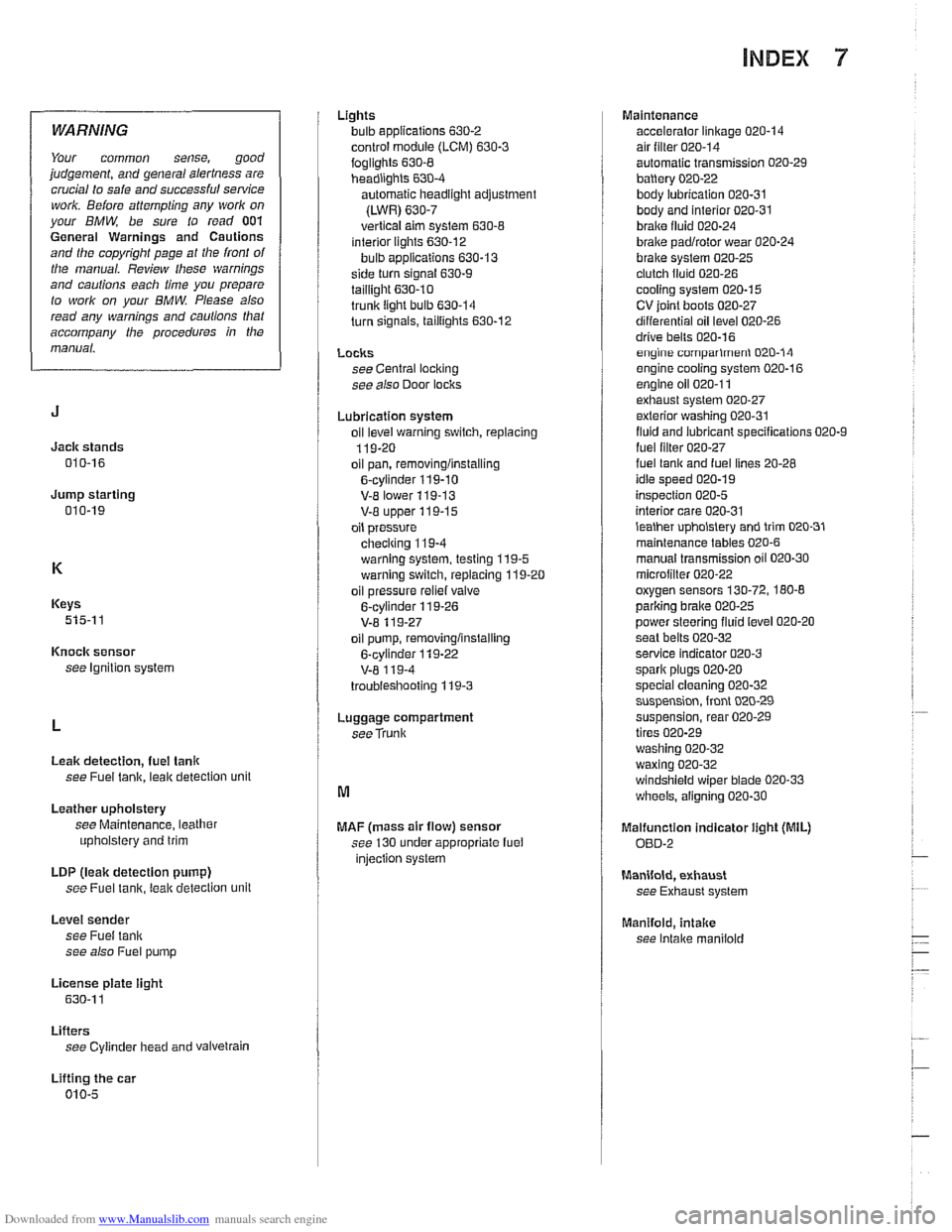
Downloaded from www.Manualslib.com manuals search engine
INDEX 7
WARNING
Your common sense, good
judgement, and general alertness are
crucial to safe and successful service
work. Before
attempting any work on
your BMW, be sure to read 001
General Warnings and Cautions
and the copyright page at the front of
the manual. Review these warnings
and cautions each time you prepare
to
work on your BMW. Please also
read any warnings and
caulions that
accompany
/he procedures in the
manual.
Jack stands
010-16
Jump starting 010-19
Keys
515-1 1
Knock sensor
see Ignition system
Leak detection,
fuel tanlr
see Fuel tank, leak detection unit
Leather upholstery
see Maintenance, leather
upholstery and trim
LDP
(leak detection pump)
see Fuel
tanir, leal( detection unit
Level sender
see Fuel tank
see also Fuel pump
License
plate iight
630-1 1
Lifters see Cylinder head and vaivetrain
Lifting the car
010-5 Lights
bulb applications
630-2
control module (LCM) 630-3
foglights 630-8 headiighls 630-4
automatic headlight adjustment
(LWR)
630-7
vertical aim system 630-8 interior lights 630-12
bulb applications 630-13
side turn signal 630-9
taillight 630.10 trunk light bulb 630-14
turn signals, taillights 630-12
LOClCS see Central loci(ing
see also Door loclrs
Lubrication system
oil
level warning switch, replacing
119-20
oil pan, removinglinstalling
6-cylinder 119-10
V-E lower 119-13 V-8 upper 119-15
oil pressure
checiring 11
9-4
warning system, testing 119-5 warning switch, replacing 119-20
oil pressure
reliel valve
6-cylinder 119-26
V-8 11 9-27
oil pump, removinglinstalling
6-cylinder
119-22
V-8 1 19-4
troubieshooting 119-3
Luggage compartment
seeTrunk
MAF (mass air flow) sensor
see 130 under appropriate fuel
injection system Maintenance
accelerator linkage
020-14 air filter 020-14
automatic transmission 020-29
battery 020-22
body lubrication 020-31 body and interior 020-31
braire fluid 020-24
brake padlrotor wear 020-24
brake system 020-25 clutch fluid 020-26
cooling system 020-15
CV ioint boots 020-27
differential oil level 020-26
drive bells 020-16 engine comparlmenl 020-14
engine cooling system 020-16
engine oil 020-1 1 exhaust system 020-27
exterior washing 020-31
fluid and lubricant specifications 020-9
fuel lilter 020-27 fuel lanir and fuel lines 20-28
idle speed 020-19
inspection 020-5
interior care 020-31
lealher upholslery and trim 020-31
maintenance tables 020-6
manual transmission oil 020-30
microiilter 020-22 oxygen sensors 130-72, 180-8
parlcing brake 020-25
power steering fluid level 020-20
seat belts
020-32 service indicator 020-3
spark plugs 020-20
special cleaning 020-32 suspension, front 020-29
suspension, rear 020-29
tires 020-29
washing
020-32
waxing 020-32 windshield wiper blade 020-33
wheels, aligning 020-30
Malfunction indicator iight (MIL)
OED-2
Manifold, exhaust
see Exhaust system
Manifold,
intake
see Intake maniiold