light BMW 540i 1998 E39 User Guide
[x] Cancel search | Manufacturer: BMW, Model Year: 1998, Model line: 540i, Model: BMW 540i 1998 E39Pages: 1002
Page 40 of 1002
Downloaded from www.Manualslib.com manuals search engine
--- -
Maintenance
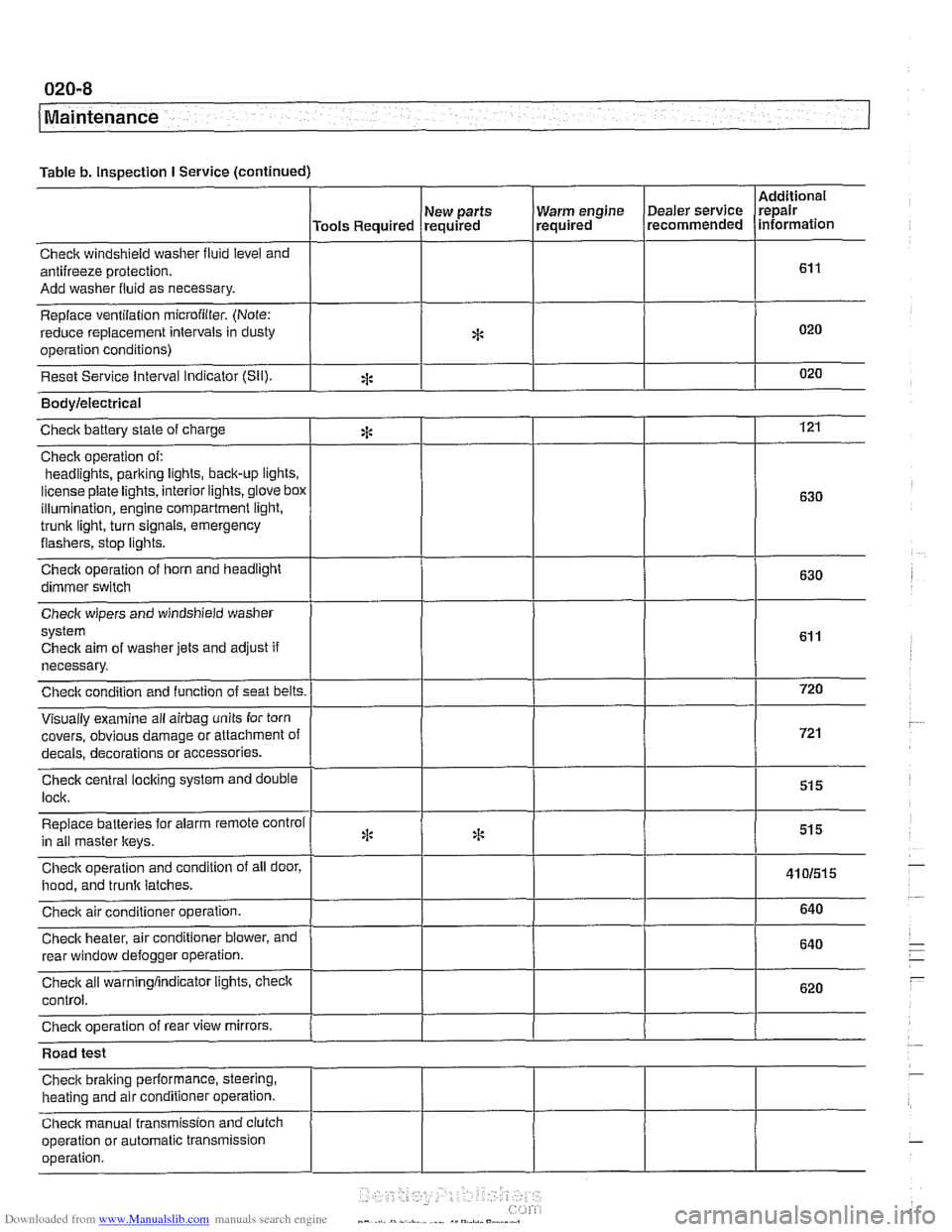
Table b. Inspection I Service (continued)
I I I I
Warm engine Dealer service
required recommended
Check windshield
washer fluid level and
antifreeze protection.
Add washer fluid as necessary.
Replace ventilation
microfilter. (Note:
reduce replacement intervals in dusty
operation conditions)
Reset Service interval Indicator
(Sil).
Additional
repair
information
Tools Required
*
eck aim of washer jets and adjust if
necessary.
covers, obvious damage or attachment o
s or accessories.
Road test
Check braking performance, steering,
heating and air conditioner operation.
Check manual transmission and clutch
operation or automatic transmission
operation. New
parts
required
*
Bodylelectrical
121
630
630
Checic battery state of charge
Check operation of:
headlights,
parking iights, back-up lights.
license plate lights, interior lights,
glove box
illumination, engine compartment light,
trunk light, turn signals, emergency
flashers, stop iights.
Check operation of horn and headlight
dimmer switch
:i:
Page 46 of 1002
Downloaded from www.Manualslib.com manuals search engine
020-1 4
Maintenance
- When oil flow has diminished to an occasional drip, reinstall
drain plug with a new metal sealing washer and torque plug.
Tightening torque Engine oil drain plug to oil pan
25 Nrn (1.8 ft-lb)
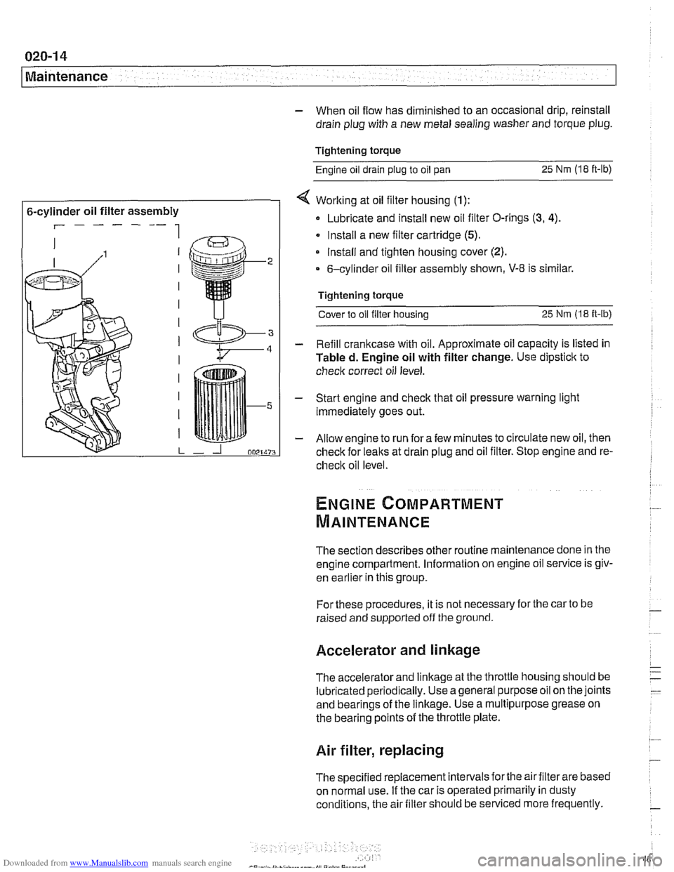
6-cylinder oil filter assembly
r------ 1
< Working at oil filter housing (1):
Lubricate and install new oil filter O-rings (3, 4).
Install a new filter cartridge (5).
lnstall and tighten housing cover (2).
6-cylinder oil filter assembly shown, V-8 is similar.
Tightening torque Cover to oil filter housing
25 Nm (1.8 it-lb)
- Refill crankcase with oil. Approximate oil capacity is listed in
Tabled. Engine oil with filter change. Use dipstick to
check correct oil level.
- Start engine and check that oil pressure warning light
immediately goes out.
- Allow engine to run fora few minutes to circulate new oil, then
check for leaks at drain plug and oil filter. Stop engine and re-
check oil level
The section describes other routine maintenance done in the
engine compartment. Information on engine oil service is
giv-
enkar~ier inthis group.
For these procedures, it is not necessary for the car to be
raised and supported off the ground.
Accelerator and linkage
The accelerator and linkage at the throttle housing should be
lubricated periodically. Use ageneral purposeoil on the joints
and bearings of the linkage. Use a multipurpose grease on
the bearing points of the throttle plate.
Air filter, replacing
The specified replacement intervals forthe air filter are based
on normal use. If the car is operated primarily in dusty
conditions, the air filter should be serviced more frequently.
Page 51 of 1002
Downloaded from www.Manualslib.com manuals search engine
Maintenance
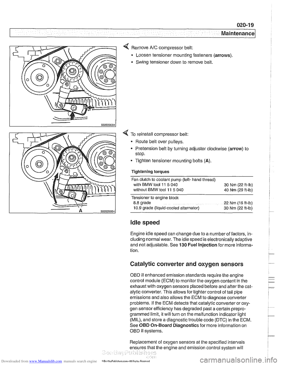
< Remove NC compressor belt:
Loosen tensioner mounting fasteners (arrows)
Swing tensioner down to remove belt.
4 To reinstall compressor belt:
Route belt over pulleys.
* Pretension belt by turning adjuster clockwise (arrow) to
stop.
- Tighten tensioner mounting bolts (A).
Tightening torques
Fan clutch to coolant pump (left- hand thread)
with BMW tool
11 5 040
30 Nm (22 ft-lb)
without BMW tool 11 5 040
40 Nm (29 ft-lb)
Tensioner to engine block
8.8 grade
22 Nm (16 ft-lb)
10.9 grade (Ilquid-cooled alternator) 30 Nm (22 ft-lb)
Idle speed
Engine idle speed can change due to a number of factors, in-
cluding normal wear. The idle speed is electronically adaptive
and not adjustable. See
130 Fuel Injection for more informa-
tion.
Catalytic converter and oxygen sensors
OBD II enhanced emission standards require the engine
control module (ECM) to monitor the oxygen content in the
exhaust with oxygen sensors placed before and after the cat-
alytic converter. This allows for tighter control of tail pipe
emissions and also allows the ECM to diagnose converter
problems. If the ECM detects that catalytic converter or oxy-
gen sensor efficiency has degraded past a certain
prepro-
grammed limit, it will turn on the malfunction indicator light
(MIL), and store a diagnostic trouble code (DTC) in the ECM.
See OBD On-Board Diagnostics for more information on
OBD
ll systems.
Replacement of oxygen sensors at the specified intervals
he engine and emission control system will
Page 54 of 1002
Downloaded from www.Manualslib.com manuals search engine
020-22 Maintenance
1
- Installation is reverse of removal, bearing in mind the
following:
Lightly lubricate new
spark plug threads with
copper-based anti-seize compound.
Thread plugs into cylinder head by hand to prevent
cross-threading.
. Be sure to reinstall and tighten coil grounds.
Tightening torque Spark plug
to cylinder head 25 Nm (18 It-lb)
Interior ventilation microfilter, replacing
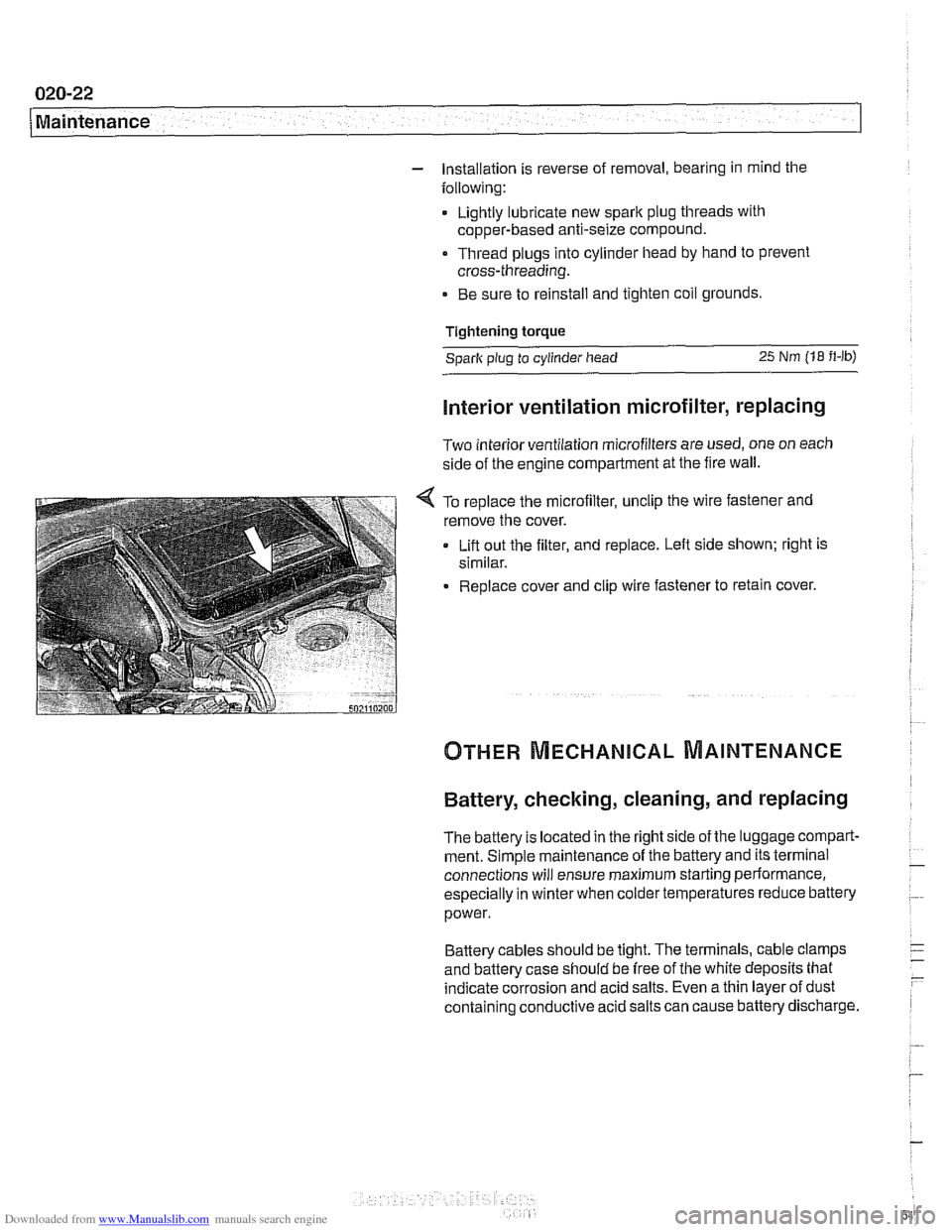
Two interior ventilation microfilters are used, one on each
side of the engine compartment at the fire wall.
< To replace the microfilter, unclip the wire fastener and
remove the cover.
Lift out the filter, and replace. Left side shown; right is
similar.
Replace cover and clip wire fastener to retain cover.
Battery, checking, cleaning, and replacing
The battery Is located in the right side of the luggage compart-
ment. Simple maintenance of the battery and its terminal
connections will ensure maximum starting periormance,
especially in winter when colder temperatures reduce battery
power.
Battery cables should be tight. The terminals, cable clamps
and battery case should be free of the white deposits that
indicate corrosion and acid salts. Even a thin layer of dust
containing conductive acid salts can cause battery discharge.
Page 55 of 1002
Downloaded from www.Manualslib.com manuals search engine
Maintenance
- To remove battery corrosion:
Disconnect battery cables. Disconnect negative (-)cable
first.
* Remove battery from trunk
Clean terminal posts and cable clamps with a wire brush.
Clean main chassis ground terminal next to battery.
Corrosion can be washed away with a
baking soda and
water solution that will neutralize acid.
Reinstall battery and reconnect cable clamps, positive
(+)
cable first.
Lightly coat outside of terminals, hold down screws, and
clamps with petroleum jelly, grease, or a commercial
battery terminal corrosion inhibitor.
WARNING
-
Battery acid is extremely dangerous. Take care to keep it
from contacting eyes, skin, or clothing. Wear eye protection.
Extinguish all
smolihg materials and do not work near any
oaen flames.
CAUTION-
Prior to disconnecting the batteg read the battery discon-
nection cautions given in
001 General Cautions and
Warnings.
NOTE-
The original equipment battery in E39 models is mainte-
nance free. The original electrolyte will normally last the
entire service life of the battery under moderate climate con-
ditions.
Battery electrolyte should be maintained at the correct level
just above the battery plates and theirseparators. The correct
level is approximately
5 mm ('14 in.) above the top of battery
plates or to the top of the indicator
marks (if applicable). The
battery plates and the indicator marks can be seen once the
fillercaps are removed.
if theelectrolyte level is low, replenish
it by adding distilled water only.
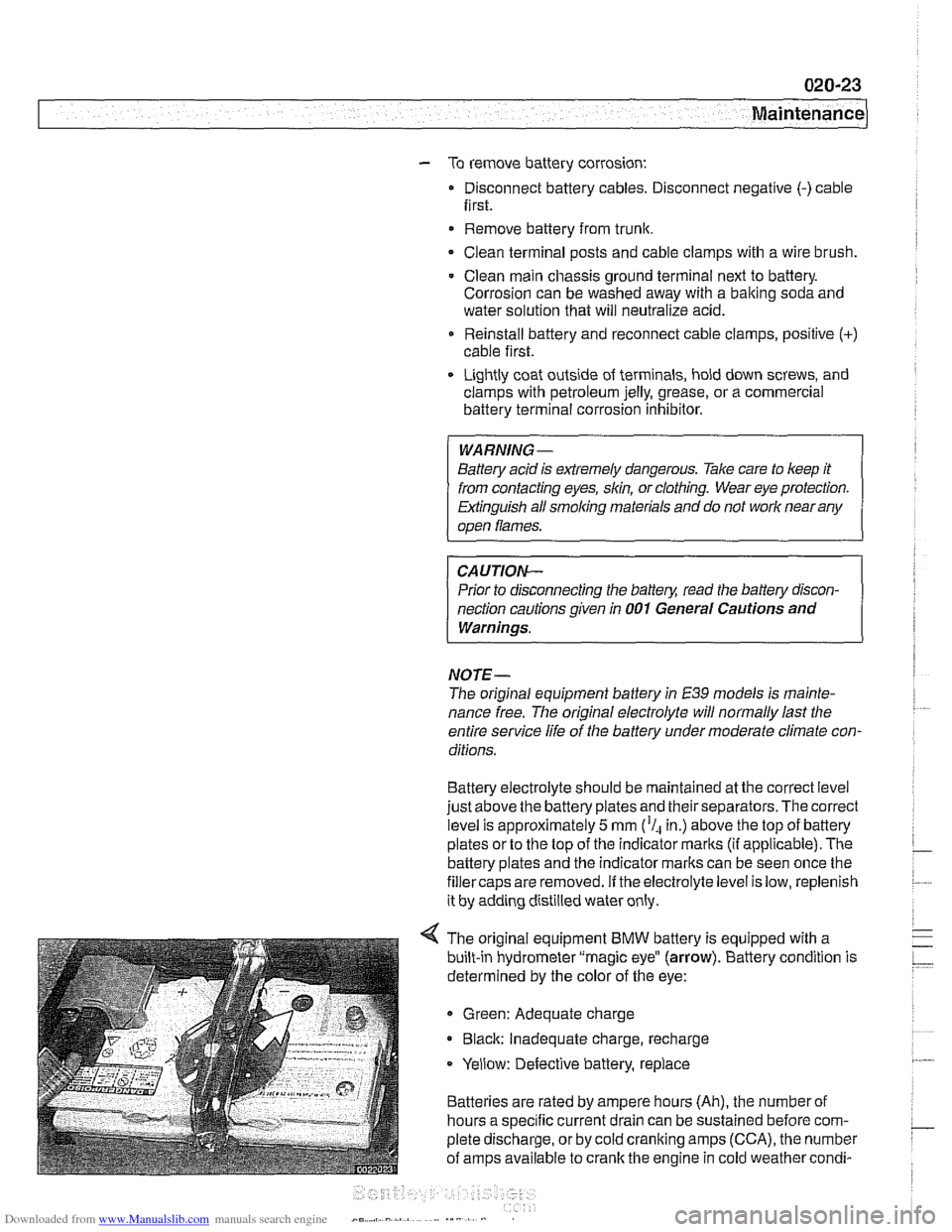
4 The original equipment BMW battery is equipped with a
built-in hydrometer "magic eye"
(arrow). Battery condition is
determined by the color of the eye:
Green: Adequate charge
* Black: Inadequate charge, recharge
Yellow: Defective battery, replace
Batteries are rated by ampere hours (Ah), the number of
hours a specific current drain can be sustained before com-
plete discharge, or by cold cranking amps (CCA), the number
of amps available to crank the engine in cold weather
condi-
Page 63 of 1002
Downloaded from www.Manualslib.com manuals search engine
Maintenance
BODY AND INTERIOR MAINTENANCE
Body and hinges, lubricating
Door locksand loclccylinderscan be lubricated with an oil that
contains graphite.
Body and doorhinges, hood latch and doorcheclc rods should
be lubricated with
SAE 30 or SAE 40 engine oil. Lubricate
seat runners with multipurposegrease. Do not apply any oil to
rubber parts.
If door weather-strips are sticking, lubricate
them with silicone spray or talcum powder. The hood release
cable should be lubricated as well.
The use of winter
lock deicer sprays should be lkept to an
absolute minimum, as the alcohol in the deicer will wash the
grease out of the lock assemblies and may cause locks to
corrode internally or to become difficult to operate.
Exterior washing
The longer dirt is left on the paint, the greater the risk of dam-
aging theglossy finish,
eitherby scratching or by thechemical
effect dirt particles may have on the painted surface.
Do not wash the car in direct sunlight. If the engine hood is
warm, allow it to cool. Beads of water not only leave spots
when dried rapidly by the sun or heat from theengine, but also
can act as small magnifying glasses and burn spots into the
finish. Wash the car with a mixture of lukewarm water and a
car wash product. Rinse using plenty of clear water. Wipe the
body dry with a sofl cloth towel or chamois to prevent
water-spotting.
Interior care
Dirt spots can usually be removed with lultewarm soapy water
or a dry foam cleaner. Use spot remover for grease and oil
spots. Do not pour the liquid directly on the carpet or fabric,
but dampen a clean cloth and rub carefully, starting at the
edge of the spot and working inward. Do not use gasoline,
naphtha, or other flammable substances.
Leather upholstery and trim
Leather upholstery and trim should be periodically cleaned
using a slightly damp cotton or wool cloth. The idea is to get
rid of the dirt in the creases and pores that can cause brittle-
ness and premature aging. On heavily soiled areas, use a
mild detergent (such as
wooliteQ) or other specially formulat-
ed leather cleaners. Dry the trim and upholstery completely
Page 65 of 1002
Downloaded from www.Manualslib.com manuals search engine
ing at the finish when it is wet. If the water coats the paint in
smooth sheets instead of forming beads that roll off, a new
coat of wax is needed. Waxshould not be applied to black trim
pieces, rubber, or other plastic parts.
Windshield wiper blade maintenance
Common problems with the windshield wipers include streak-
ing or sheeting, water drops afler wiping, and blade chatter.
Streaking is usually caused when wiper blades are coated
with road
film or car wash wax. Clean the blades using soapy
water.
If cleaning the blades does not cure the problem, they
should be replaced. BMW recommends replacing the wiper
I blades twice a year, before and after the cold season.
I
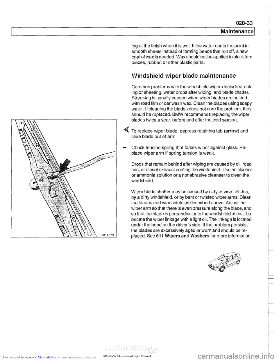
< To replace wiper blade, depress retaining tab (arrow) and
slide blade out of arm.
I - Checlc tension spring that forces wiper against glass. Re-
place wiper arm if spring tension is weak.
Drops that remain behind after wiping are caused by oil, road
film, or diesel exhaust coating the windshield. Use an alcohol
or ammonia solution or a nonabrasive cleanser to clean the
windshield.
Wiper blade chatier may be caused by dirty or worn blades,
by a dirty windshield, or by bent or twisted wiper arms. Clean
the blades and windshield as described above.
Adjusithe
wiper arm so that there is even pressure along the blade, and
so that the blade is perpendicularto the windshield at rest. Lu-
bricate the wiper linkage with a light oil. The
linkage is located
under the hood on the driver's side. If the problem persists,
the blades are excessively aged or worn and should be re-
placed. See
61 1 Wipers and Washers for more information.
Page 70 of 1002
Downloaded from www.Manualslib.com manuals search engine
100-4
I Engine-General
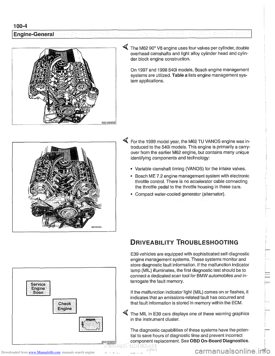
The M62 90" V8 engine uses four valves per cylinder, double
overhead camshafts and light alloy cylinder head and cylin-
der
bloclc engine construction.
On 1997 and 1998 540i models, Bosch engine management
systems are utilized. Table a lists engine management sys-
tem applications.
4 For the 1999 model year, the M62 TU VANOS engine was in-
troduced to the 540i models. This engine is primarily a carry-
over from the earlier M62 engine, but contains many unique
identifying components and technology:
Variable camshaft timing (VANOS) for the intake valves.
Bosch ME 7.2 engine management system with electronic
throttle control. There is no accelerator cable connecting
the throttle pedal to the throttle housing in these cars.
Compact water-cooled generator (alternator).
E39 vehicles are equipped with sophisticated self-diagnostic
engine management systems. These systems monitor and
store diagnostic fault information. If the malfunction indicator
lamp (MIL) illuminates, the first diagnostic test should be to
connect a dedicated scan tool for BMW automobiles and in-
terrogate the fault memory.
If the malfunction indicator light (MIL) comes on orflashes, it
indicates that an emissions-related fault has occurred and
that fault information is stored in memory within the ECM.
4 The MIL in E39 cars displays one of these warning graphics
in the instrument cluster.
The diagnostic capabilities of these systems have the poten-
tial to save hours of diagnostic time and prevent incorrect
5 placement. See OBD On-Board Diagnostics.
Page 71 of 1002
Downloaded from www.Manualslib.com manuals search engine
Two common causes of driveability problems are incorrect
system voltage and bad grounds.
System voltage
Digital motor electronics (DME) requires that the system (bat-
tery) voltage be maintained within a narrow range of DC volt-
age.
DC voltage levels beyond or below the operating range,
or any
AIC voltage in the electrical system can cause havoc.
When troubleshooting an illuminated MIL, make sure the bat-
tery is fully charged and capable of delivering all its power to
the electrical system. An undercharged battery can amplify
AIC alternator output ripple.
To
make a quick check of the battery charge, measure the
voltage across the battery terminals with all cables attached
and the ignition off.
Afully charged battery will measure 12.6
volts or slightly more, compared to 12.1 5 volts for a battery
with a 25% charge.
The DME system operates at low voltage and current levels,
making it sensitive to small increases in resistance. The elec-
trical system is routinely subjected to corrosion, vibration and
wear, so faults or corrosion in the wiring harness and connec-
tors are not uncommon. Check the battery terminals
forcorro-
sion or loose cable connections. See 121 Battery, Starter,
Alternator for additional information.
If a battery cable connection has no
v~sible faults but is still
suspect, measure the voltage drop across the connection. A
large drop indicates excessive resistance, meaning that the
connection is corroded, dirty, or damaged. Clean or repairthe
connection and retest.
NOTE-
For instructions on conducting a voltage drop test and other
general electrical troubleshooting information, see
600 Elec-
trical System-General.
Visually inspect all wiring, connectors, switches and fuses in
the system. Loose or damaged connectors can cause inter-
mittent problems, especially the small terminals in the ECM
connectors. Disconnect the wiring harness connectors to
check for corrosion, and use electrical cleaning spray to re-
move contaminants.
Main grounds
Good grounds are critical to proper DME operation. If a
ground connection has no visible faults but is still suspect.
measure the voltage drop across the connection. A large volt-
age drop means high resistance. Clean or repair the connec-
tion and retest.
LBuntr.yP~sbhnllcn.can#-AII A,~iltl Rcsrwsd
Page 72 of 1002
Downloaded from www.Manualslib.com manuals search engine
100-6
( Engine-General
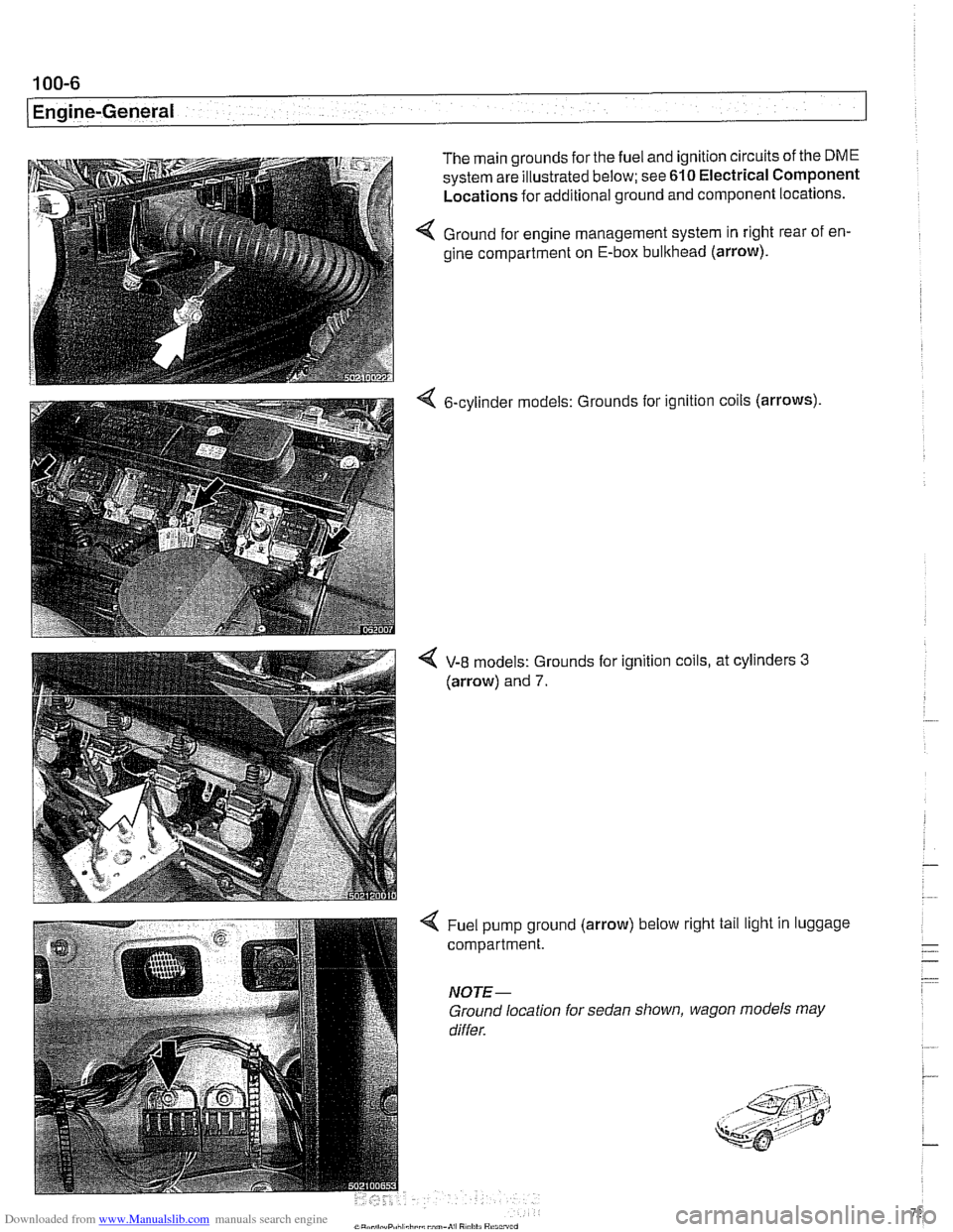
The main grounds for the fuel and ignition circuits of the DME
system are illustrated below; see 610 Electrical Component
Locations for additional ground and component locations.
4 Ground for engine management system in right rear of en-
gine compartment on E-box bulkhead (arrow).
6-cylinder models: Grounds
for ignition coils (arrows)
4 V-8 models: Grounds for ignition coils, at cylinders 3
(arrow) and 7.
4 Fuel pump ground (arrow) below right tail light in luggage
compartment.
NOTE-
Ground location for sedan shown, wagon models may
differ.