tow BMW 540i 1998 E39 User Guide
[x] Cancel search | Manufacturer: BMW, Model Year: 1998, Model line: 540i, Model: BMW 540i 1998 E39Pages: 1002
Page 133 of 1002
Downloaded from www.Manualslib.com manuals search engine
. - -- -
Cylinder Head Removal and Installation --
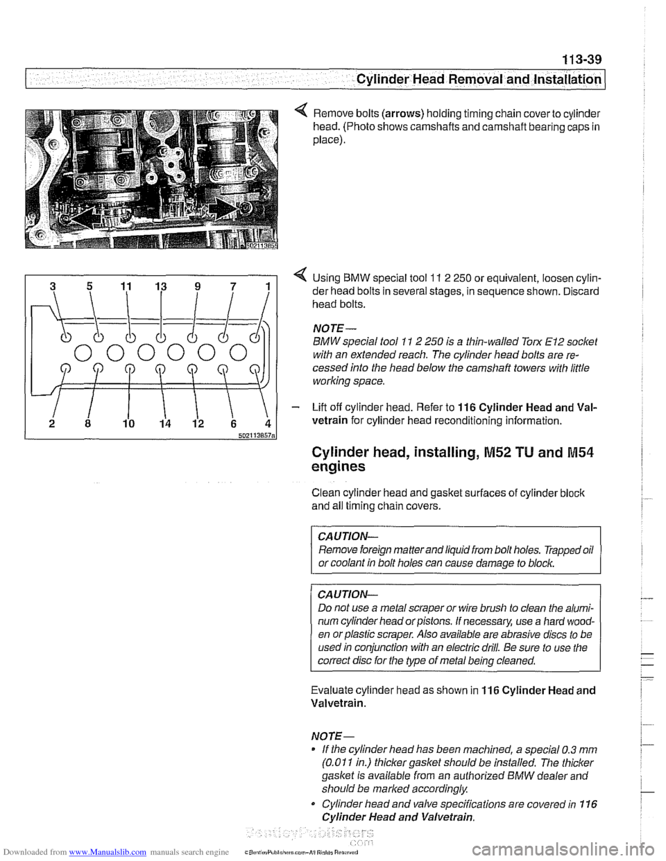
Remove bolts (arrows) holding timing chain cover to cylinder
head. (Photo shows camshafts and camshaft bearing caps in
place).
4 Using BMW special tool 11 2 250 or equivalent, loosen cylin-
der head bolts in several stages, in sequence shown. Discard
head bolts.
NOJE-
BMW special tool 11 2 250 is a thin-walled Torx El2 socket
with an extended reach. The cylinder head bolts are re-
cessed into the head below the
camshaft towers with little
working space.
- Lift off cylinder head. Refer to 116 Cylinder Head and Val-
vetrain for cylinder head reconditioning information.
Cylinder head, installing, M52 TU and M54
engines
Clean cylinder head and gasket surfaces of cylinder bloclc
and all timing chain covers.
CAUTION- Remove foreign matter and liquid from bolt holes. Trapped oil
or coolant in bolt holes can cause damage to
blocl~,
CAUJION-
Do not use a metal scraper or wire brush to clean the alumi-
num cylinder head or pistons. If necessary, use a hard wood-
en orplastic scraper. Also available are abrasive discs to be
used in conjunction with an electric drill. Be sure to use the
correct disc for the type of metal being cleaned.
Evaluate cylinder head as shown in
116 Cylinder Head and
Valvetrain.
NOTE- If the cylinder head has been machined, a special 0.3
mm
(0.01 1 in.) thicker gasket should be installed. The thicker
gasket is available from an authorized
BMW dealer and
should be marked accordingly
Cylinder head and valve specifications are covered in 116
Cylinder Head and Valvetrain.
Page 252 of 1002
Downloaded from www.Manualslib.com manuals search engine
Camshaft Timing Chain -- - -1
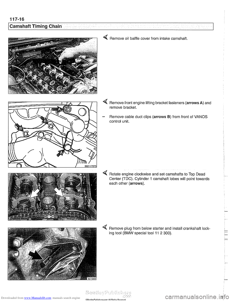
Q Remove oil baffle cover
from intake
camshaft
Remove front engine lifting bracket fasteners (arrows
A) and
remove bracket.
- Remove cable duct clips (arrows B) from front of VANOS
control unit.
Rotate engine
clocltwise and set camshafts to Top Dead
Center (TDC). Cylinder
1 camshaft lobes will point towards
each other (arrows).
4 Remove plug from below starter and install crankshaft lock-
ing tool
(BMW special tool 11 2 300).
Page 265 of 1002
Downloaded from www.Manualslib.com manuals search engine
Camshaft Timing chain1
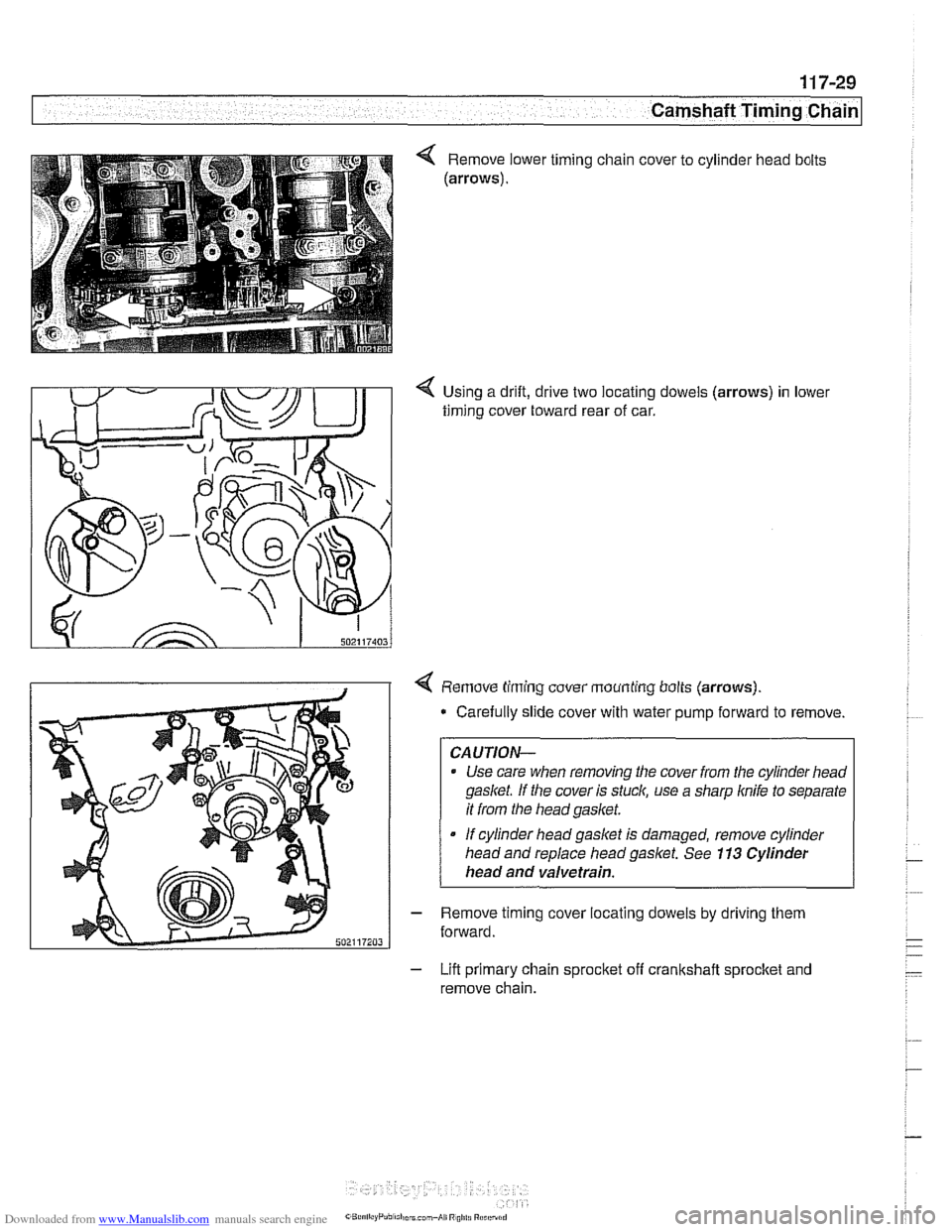
Using a drift, drive two locating dowels (arrows) in lower
timing cover toward rear of car.
4 Remove timing cover mounting bolts (arrows).
* Carefully slide cover with water pump forward to remove
CAUTION-
Use care when removing the cover from the cylinder head
gasket If the cover is stuck, use a sharp knife to separate
it from the head gasket.
If cylinder head gasket is damaged, remove cylinder
head and replace head
gaslet. See 113 Cylinder
head and valvetrain.
- Remove timing cover locating dowels by driving them
forward.
- Lift primary chain sprocket off crankshaft sprocket and
remove chain.
Page 275 of 1002
Downloaded from www.Manualslib.com manuals search engine
11 7-39
Camshaft Timing Chain
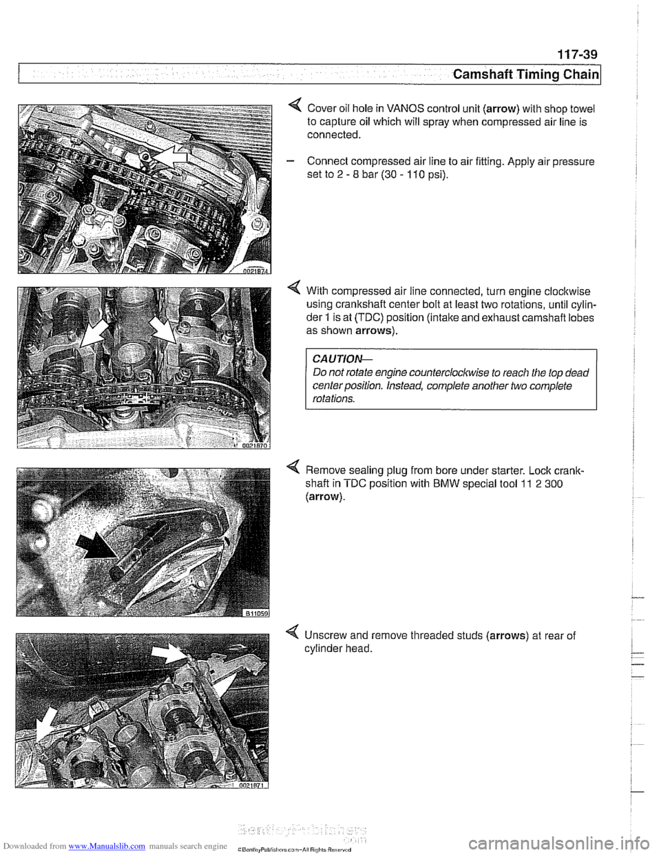
4 Cover oil hole in VANOS control unit (arrow) with shop towel
to capture oil which will spray when compressed air line is
connected.
- Connect compressed air line to air fitting. Apply air pressure
set to
2 - 8 bar (30 - 110 psi).
4 With compressed air line connected, turn engine clocltwise
using crankshaft center bolt at least two rotations, until cylin-
der
1 is at (TDC) position (intake and exhaust carnshafl lobes
as shown arrows).
Do not rotate engine
countercloclwise to reach the top dead
centerposition. Instead, complete another two complete
Remove sealing plug from bore under starter. Lock
crank-
shafl in TDC position with BMW special tool 11 2 300
(arrow).
-
4 Unscrew and remove threaded studs (arrows) at rear of
cylinder head.
Page 277 of 1002
Downloaded from www.Manualslib.com manuals search engine
Camshaft Timing Chain
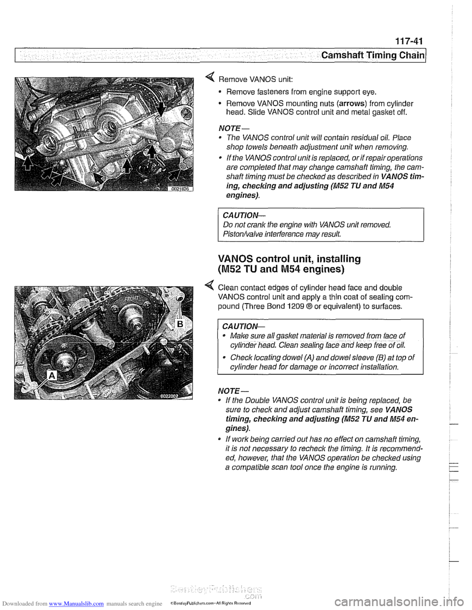
4 Remove VANOS unit:
Remove fasteners from engine support eye.
Remove VANOS mounting nuts (arrows) from cylinder
head. Slide VANOS control unit and metal gasltet off.
NOJE-
The VANOS control unit will contain residual oil. Place
shop towels beneath adjustment unit when removing.
If the VANOS control unit is replaced, or if repair operations
are completed that may change camshaft timing, the cam-
shaft timing must be checked as described in VANOS tim-
ing,
checlcing and adjusting (M52 JU and M54
engines).
CAUJION-
Do not crank the engine with VANOS unit removed.
Piston/valve interference may result.
VANOS control unit, installing
(M52 TU and M54 engines)
< Clean contact edges of cylinder head face and double
VANOS control unit and apply a thin coat of sealing com-
pound (Three Bond
1209 8 or equivalent) to surfaces.
I CAUJION-
. Make sure all gaskel material is removed from lace of
cyl~nder head. Clean sealing lace and keep lree of oil.
Checklocating dowel (A) and dowelsleeve (B) at top of
cylinder head for damage or incorrect installation.
NO
JE -
If the Double VANOS control unit is beino reolaced. be -.
sure to check and adjust camshaft timing, see VA NOS
timing, checking and adjusting (M52 JU and M54 en-
gines).
* If work being carried out has no effect on camshaft timing,
it is not necessary to recheck the timing. It is recommend-
ed, however, that the VANOS operation be checked using
a compatible scan tool once the engine is running.
Page 324 of 1002
Downloaded from www.Manualslib.com manuals search engine
-
I Lubrication System - I
Oil pressure, checking
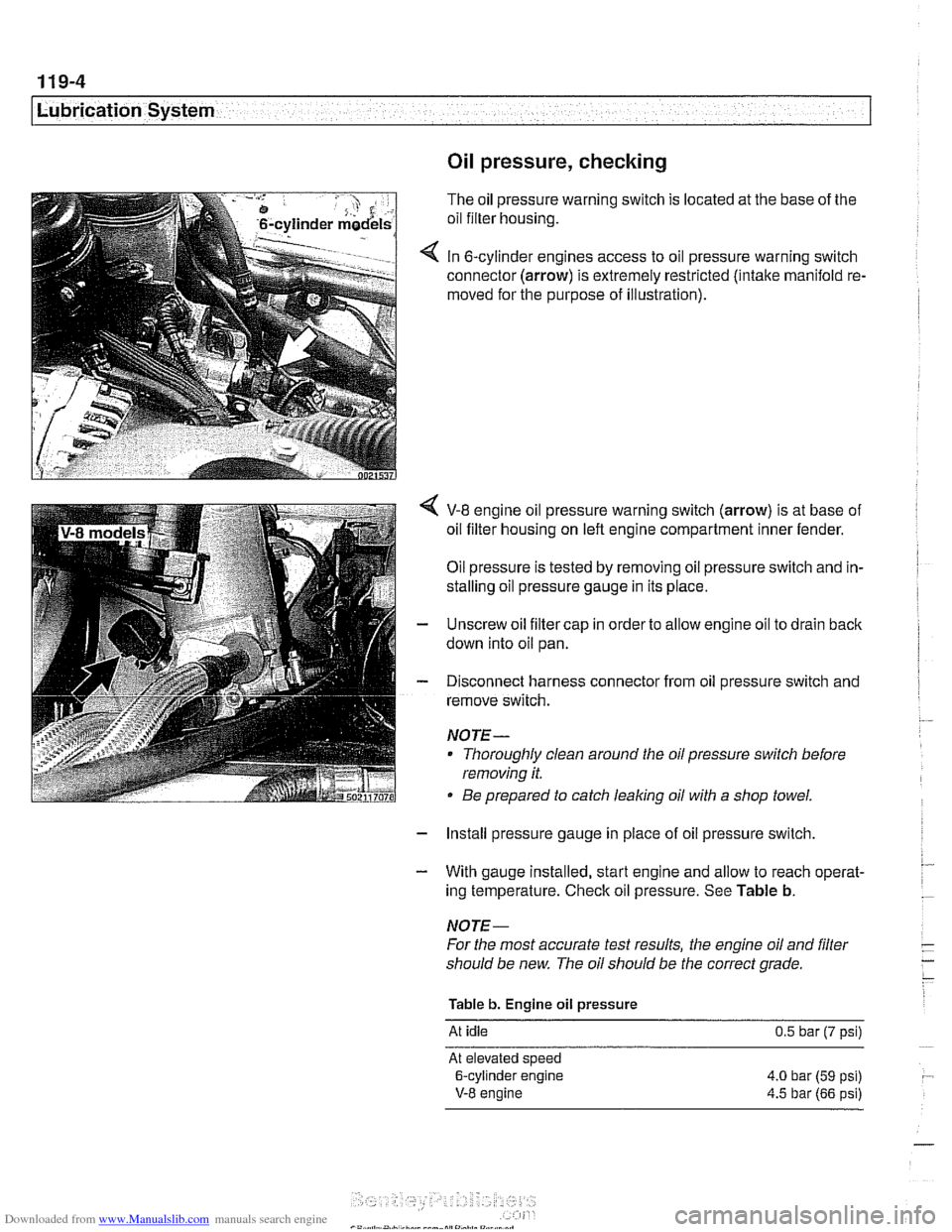
The oil pressure warning switch is located at the base of the
oil filter housing.
In 6-cylinder engines access to oil pressure warning switch
connector (arrow) is extremely restricted (intake manifold re.
moved for the purpose of illustration).
V-8 engine oil pressure warning switch (arrow) is at base of
oil filter housing on left engine compartment inner fender.
Oil pressure is tested by removing oil pressure switch and in-
stalling oil pressure gauge in its place.
Unscrew oil filter cap in order to allow engine oil to drain back
down into oil pan.
Disconnect harness connector from oil pressure switch and
remove switch.
NOJE-
Thoroughly clean around the oil pressure switch before
removing it.
Be prepared to catch leaking oil with a shop towel.
- Install pressure gauge in place of oil pressure switch,
- With gauge installed, start engine and allow to reach operat-
ing temperature. Check oil pressure. See Table b.
NOJE-
For the most accurate test results, the engine oil and filter
should be new. The oil should be the correct grade.
Table b. Engine oil pressure
At idle 0.5 bar (7 psi)
At elevated speed
6-cylinder engine 4.0 bar
(59 psi)
V-8 engine 4.5 bar (66 psi)
Page 396 of 1002
Downloaded from www.Manualslib.com manuals search engine
130-6
Fuel Injection
Fuel supply to the injection system is provided by a high pres-
sure electric pump mounted inside the fuel tank. The pump is
powered via the fuel pump relay. If the relay is faulty, the fuel
pump will not run and the engine will not start.
NOTE-
* Fuel delivery volume and fuel pressure are critical to prop-
er operation. Fuel pressure direcfly influences fuel deliv-
ery
Fuel pump relay, fuel pressure and fuel volume tests are
given in 160 Fuel Tank and Fuel Pump.
Relieving system fuel pressure
The fuel system retains fuel pressure in the system when the
engine is off. To prevent fuel from spraying on a hot engine,
system fuel pressure should be relieved beforedisconnecting
fuel lines. One method is to tightly wrap
ashop towel around a
fuel line fitting and loosen or disconnect the fitting. Cleanli-
ness is essential when working with fuel components. Thor-
oughly clean the unions before disconnecting fuel lines.
When system faults are detected, a diagnostic trouble code
(DTC) is stored in the engine control module (ECM). The MIL
also iiluminates if an emissions-related fault is detected
When faults arise, or if the malfunction indicator lamp (MIL) is
illuminated, begin troubleshooting by connecting BMW ser-
vice tester
DISplus. MoDiC, GTI or equivalent scan tool. The
capabilities of OBD
II software has the potential to save hours
of diagnostic time and to help avoid incorrect component re-
placement and possible damage to system components.
CAUTION-
- The tests in this section may set fault codes (DTCs) in the
ECM and illuminate the
MIL. Affer all testing is completed,
access and clear DJC fault memory using an
OED I1 or
BMW compatible scan tool. See OBD On-Board Diag-
nostics.
0 Only use a digital multimeter for electrical tests.
. Relay positions can vary Be sure to confirm relay posi-
tion by identifying the wiring in the socket using the wir-
ing diagrams found in ELE Electrical Wiring
Diagrams.
Page 406 of 1002
Downloaded from www.Manualslib.com manuals search engine
I Fuel Injection
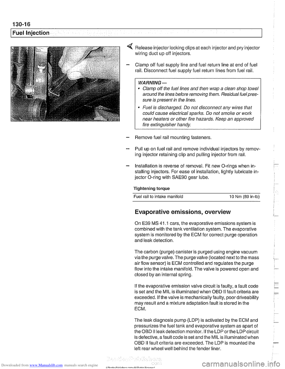
Release injector locking clips at each injector and pry injector
wiring duct up off injectors.
Clamp off fuel supply line and fuel return line at end of fuel
rail. Disconnect fuel supply fuel return lines from fuel rail.
WARNING -
Clamp off the fuel lines and then wrap a clean shop towel
around the lines before removing them. Residual
fuelpres-
sure is present in the lines.
Fuel is discharged. Do not disconnect any wires that
could cause electrical
sparks. Do not smoke or work
near heaters or other fire hazards. Keep an approved
I fire extinguisher handy. I
- Remove fuel rail mounting fasteners
- Pull up on fuel rail and remove individual injectors by remov-
ing injector retaining clip and pulling injector from rail.
- Installation is reverse of removal. Fit new O-rings when in-
stalling injectors. For ease of installation, lightly lubricate in-
jector O-ring with
SAE9O gear lube.
Tightening torque Fuel rail to
intake manifold 10 Nm (89 in-lb)
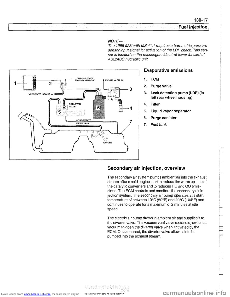
Evaporative emissions, overview
On E39 MS 41 .I cars, the evaporative emissions system is
combined with the tank ventilation system. The evaporative
system is monitored by the ECM for correct purge operation
and leak detection.
The carbon (purge) canister is purged using engine vacuum
via the
purgevalve.The purgevalve (located nextto the mass
airflow sensor) is ECM controlled and regulates the purge
flow into the intake manifold. The valve is powered open and
closed by an internal spring.
If the evaporative emission valve circuit is faulty, a fault code
is set and the MIL is illuminated when OBD
II fault criteria are
exceeded. If the valve is mechanically faulty, poor driveability
may result and a mixture adaptation fault is stored in the
ECM.
The leak diagnosis pump (LDP) is activated by the ECM and
pressurizes the fuel tank and evaporative system as apart of
theOED I1 leakdetection monitor. If the LDP orthe LDP circuit
is defective, afault code is set and the MIL is illuminated when
OBD
I1 fault criteria are exceeded. The LDP is mounted the
left rear wheel well behind the fender liner.
Page 407 of 1002
Downloaded from www.Manualslib.com manuals search engine
Fuel Injection 1
NOTE-
The 1998 5281' with MS 41.1 requires a barometric pressure
sensor input signal for activation of the
LDP check. This sen-
sor is located on the passenger side strut tower
fo~lard of
ABS/ASC hydraulic unit.
Evaporative emissions
1. ECM
2. Purge valve
3. Leak detection pump (LDP) (in
lefl rear wheel housing)
4. Filter
5. Liquid vapor separator
6. Purge canister
7. Fuel tank
Secondary air injection, overview
The secondary air system pumps ambient air into the exhaust
stream afler a cold engine start to reduce the warm up time of
the catalytic converters and to reduces HC and CO emis-
sions. The ECM controls and monitors the secondary air in-
jection system. The secondary air pump operates at a start
temperature of between 10°C (50°F) and 40°C (104°F) and
continues to operate for a maximum of
2 minutes at idle
speed.
The electric air pump draws in ambient air and supplies it to
the divertervalve. The vacuum ventvalve (solenoid) switches
vacuum to open the divertervalve when activated by the
ECM. Once opened, the diverter valve allows air to be
pumped into the exhaust stream.
Page 486 of 1002
Downloaded from www.Manualslib.com manuals search engine
.-
I Fuel Tank and Fuel Pump
- Expose right side access cover:
Peel forward lip of carpet.
Release rubber grommet from center of access cover insu-
lation.
Peel back insulation at
perforations to expose fuel tank ac-
cess cover.
Remove right side cover to expose electrical harness con-
nector.
WARNING -
Fuel may be spilled. Do not smolce or work near heaters or
other fire hazards.
When disconnecting fuel hose, wrap shop rag around
end of hose to prevent spray of fuel under pressure.
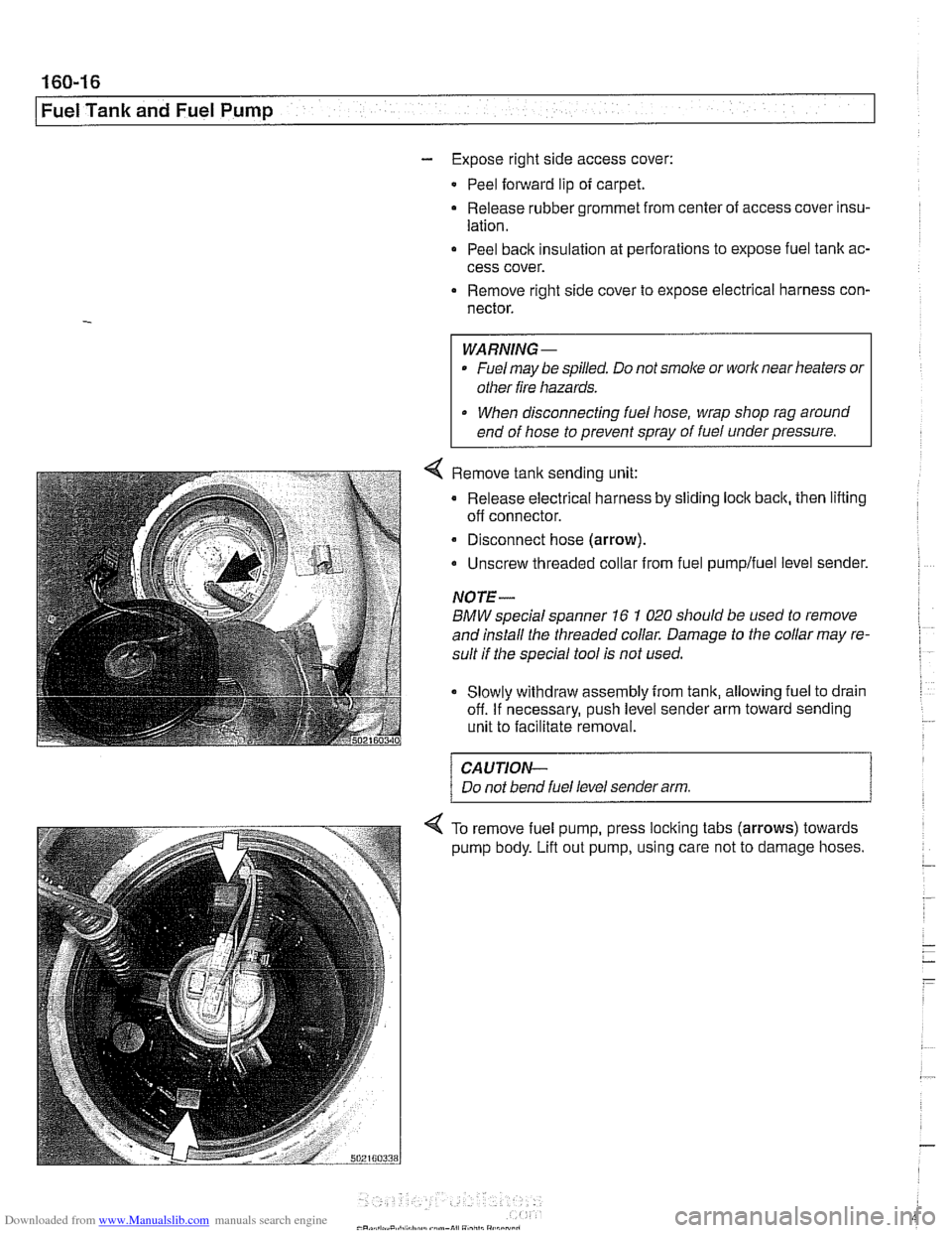
Remove
tank sending unit:
Release electrical harness by sliding lock back, then lifting
off connector.
a Disconnect hose (arrow).
Unscrew threaded collar from fuel
pumpifuel level sender.
NOTE-
BMW special spanner 16 1 020 should be used to remove
and install the threaded collar. Damage to the collar may re-
sult if the special tool is not used.
Slowly withdraw assembly from tank, allowing fuel to drain
off. If necessary, push level sender arm toward sending
unit to facilitate removal.
CAUTION-
Do not bend fuel level sender arm.
To remove fuel pump, press locking tabs (arrows) towards
pump body.
Lifl out pump, using care not to damage hoses.